TECO-Westinghouse Motor MA7200 User manual

4H358D0180009
Installation Manual
MA7200
AC Inverter
208 to 230V 1 / 3 Phase 1 ~ 3HP
3 Phase 5 ~ 40HP
380 to 460V 3 Phase 1 ~ 75HP

SAFE OPERATION NOTES
Read this instruction manual thoroughly before installation, operation, maintenance
or inspection of the inverter. Only authorized personnel should be permitted to perform
maintenance, inspections or parts replacement.
In this manual, notes for safe operation are classified as:
“WARNING” or “CAUTION”.
WARNING : Indicates a potentially hazardous situation that, if not avoided,
could result in death or serious injury to personnel.
CAUTION : Indicates a potentially hazardous situation that, if not avoided,
may result in minor or moderate injury to personnel and damage
to the equipment.
“WARNING” and “CAUTION”
WARNING
yAlways turn off the input power supply before wiring terminals.
yAfter turning OFF the main circuit power supply, do not touch the circuit
components until the “CHARGE” LED is extinguished.
yNever connect power circuit output U/T1, V/T2, W/T3 to AC power supply.
CAUTION
yWhen mounting the MA7200 in a separate enclosure, install a fan or other cooling
device to keep the intake air temperature below 113oF (45oC).
yDo not perform a withstand voltage test to the inverter.
yAll the parameters of the inverter have been preset at the factory. Do not change
the settings unnecessarily.
This inverter has been placed through demanding tests at the factory before shipment.
After unpacking, check for the following:
1. Verify that part numbers on shipping carton and unit match the purchase order
sheet and/or packing list.
2. Do not install or operate any inverter that is damaged or missing parts.
3. Do not install or operate any inverter that has no QC marking.
Contact your local TECO authorized distributor or TECO representative if any of
the above irregularities have been found.

Contents Page
1. MA7200 Handling Description ------------------------------------- 1-1
1.1 Inspection Procedure upon Receiving ---------------------------------------- 1-1
1.2 Installation------------------------------------------------------------------------ 1-2
1.3 Removing/Attaching of LCD Digital Operator and Front Cover---------- 1-4
1.4 Wiring between Inverter and Peripheral Devices --------------------------- 1-7
1.5 Description of Terminal Function --------------------------------------------1-11
1.6 Main Circuit Wiring Diagram -------------------------------------------------1-13
1.7 Wiring Main Circuit------------------------------------------------------------1-14
1.8 Inverter Specifications ---------------------------------------------------------1-17
1.9 Dimensions ----------------------------------------------------------------------1-19
1.10 Peripheral Units-----------------------------------------------------------------1-22
2. Using LCD Digital Operator----------------------------------------- 2-1
3. Parameter Setting------------------------------------------------------ 3-1
3.1 Frequency Command An- ----------------------------------------------- 3-1
3.2 Parameters That Can be Changed during Running Bn- -------------- 3-2
3.3 Control Parameters Cn- -------------------------------------------------3-12
3.4 System Parameters Sn- --------------------------------------------------3-30
3.5 Monitoring Parameters Un- ---------------------------------------------3-75
4. Fault Display and Troubleshooting ------------------------------ 4-1
4.1 General---------------------------------------------------------------------------- 4-1
4.2 Error Message and Troubleshooting ------------------------------------------ 4-2
Appendix
A. PID Parameter Setting -------------------------------------------------------App-1
B. Supplementary on PID Control Block Diagram--------------------------App-3
C. Wiring for PG Feedback Use------------------------------------------------App-4
D. RS-485 Communication Interface------------------------------------------App-5
E. SINK/SOURCE Typical Connection Diagram ---------------------------App-7
F. RS-232C Serial Communication Connection Diagram------------------App-8
G. Set-up Using the Sensorless Vector Control ------------------------------App-9
H. Notes for Circuit Protection and Environmental Ratings-------------- App-11
I. Spare Parts------------------------------------------------------------------- App-15
J. Electrical Ratings For Contstant Torque and Quadratic Torque------ App-25
K. Inverter Heat Loss ---------------------------------------------------------- App-26

No. Figure Contents Page No. Figure Contents Page
1 Air clearance for MA7200 wall mounting 1-2 27 S curve 3-27
2 Standard connection diagram 1-9 28 ASR Integral Gain 2 3-28
3 Processing the ends of twisted-pair cables 1-15 29 Deceleration to stop 3-44
4The optical-couplers connect to external
inductive load 1-15 30 Coast to Stop 3-44
5 MA7200 ground winding 1-16 31 Whole range DC Injecting Braking Stop 3-44
6 LCD digital operator dimension 1-27 32 Coast to Stop with Timer 3-45
7 Analog operator 1-28 33 Output voltage limit 3-48
8 LCD digital operator 2-1 34 Stall prevention function during deceleration 3-48
9 Acceleration and Deceleration time 3-4 35 Zero speed braking operation selection 3-49
10 Analog input gain and bias 3-5 36 Motor overload protection curve 3-51
11 Adjust the auto torque boost gain Bn-11 to
increase the output torque 3-5 37 3-wire mode connection diagram 3-53
12 Block diagram for PID control in inverter 3-7 38 Operation sequence in 3-wire mode 3-53
13 Response of PID control for step-shape
(deviation) input 3-8 39 2-wire mode connection diagram 3-53
14 PID Control Block diagram (After Version
30.18) 3-9 40 Time chart for multi-step speed and jog
command 3-54
15 An operation example of timer function 3-9 41 Acceleration and deceleration ramp hold 3-55
16 Time chart for energy-saving operation 3-10 42 Time chart for DC injection braking command 3-57
17 User-defined V/F curve 3-15 43 PG speed control block diagram 3-58
18 Output frequency with slip compensation. 3-16 44 Time chart of output frequency with the
UP/DOWN function 3-59
19 Slip compensation limit 3-16 45 Pulse signal output 3-65
20 DC injection braking time chart 3-17 46 The input/output signal in ‘Timer’ function
application 3-66
21 Upper and lower bounds of the frequency
command 3-18 47 PID control block diagram App-3
22 Setting jump frequencies 3-18 48 PID wiring diagram App-3
23 Acceleration stall prevention function 3-20 49 Wiring of PG feedback App-4
24 Run stall prevention function 3-20 50 Wiring for MODBUS Protocol communication App-5
25 Time chart for overtorque detection 3-23 51 Wiring for PROFIBUS protocol communication App-6
26 Speed search timing chart 3-25 52 RS232-C Typical Connection Diagram App-8
No. Table Contents Page
1 Main circuit terminals 1-11
2 Control circuit terminals 1-12
3230V/460V class applicable wire size and connector 1-14
4 Brake resistor list 1-22
5 AC reactor list 1-23
6 Noise filter on the input side 1-24
7 Key's functions 2-2
8 Setting of monitoring contents 3-6
9 LCD Digital Operator Display Unit 3-21
10 230V Class Inverter Capacity Selection 3-39
11 460V Class Inverter Capacity Selection 3-40
12 V/F curve of 1~2 HP compact size, 230V Class MA inverter 3-41
13 V/F curve of 3~20 HP, 230V Class MA inverter 3-42
14 Multi-Function Input Setting 3-52
15 Multi-function analog input function list 3-60
16 Multi-function output terminal function 3-63

1-1
1. MA7200 Handling Description
1.1 Inspection Procedure upon Receiving
Before delivery, Every MA7200 inverter has been properly adjusted and passed the
demanding function test. After receiving the inverter, the customer should take it out and
follow the below procedure:
•Verify that the Type No. of the inverter you’ve received is the same as the Type No.
listed on your purchase order. (Please read the Nameplate)
•Observe the condition of the shipping container and report any damage immediately to
the commercial carrier that has delivered your inverter.
■Inverter nameplate:
■Inverter model number :
INPUT SPECIFICATION
OUTPUT SPECIFICATION
Model:MA7200-2002-N1 HP:2 KVA:2.7 INVERTER MODEL
AC Input: 1PH/3PH 200-230V 50/60Hz
AC Output: 3PH 0-230V Amps: 6.4A
MOTOR COMPANY LISTED
(IND. CONT. EQ.)
848F
MA7200-2002-N1
N1: NEMA1
N4: NEMA4
0001 : 1HP
∫∫
0075 : 75HP
NEMA4 for 1~20HP only
Max. Applicable Motor
Capacity (HP)
Rated Voltage
2: 200~230V
4: 380~460V
MA7200
Series

1-2
1.2 Installation
When installing the inverter, always provide the following space to allow normal
heat dissipation.
50 mm min.
30 mm
min. 30 mm
min.
50 mm
min.
ambient
temperature
-10 ~ + 40 ℃
AIR
AIR
120 mm
min.
120 mm
min.
(a) Space in Side (b) Space in Top/bottom
Fig. 1-a. Air clearance for MA7200 wall mounting

1-3
220-240V
380-480V
Single/ThreePhases
L1(L)
3Phases IM
L2(N) L3 T3T2
T1 Single/ThreePhases
380-480V
220-240V
L2(N)L1(L) L3
3Phases IM
T1 T2 T3
(a) NEMA4 Frame1 (b) NEMA4 Frame2
Fig. 1-b. MA7200 NEMA4 Installation
CAUTION
Location of equipment is important to achieve proper performance and normal
operating life. The MA7200 inverter should be installed in area where the following
conditions exist.
yAmbient temperature: +14 to 104oF, (-10 to 40oC).
yInstall the MA7200 in a location protected from rain, moisture and direct sunlight.
yInstall the MA7200 in a location free from harmful mists, gases, liquids, airborne
dusts and metallic particles.
yInstall the MA7200 in a location free from vibration and electromagnetic noise. (i.e.
welding machines, power units, etc…)
yWhen mounting multiple units in a common enclosure, install a cooling fan or some
other means to cool the air entering the inverter to at least 113oF (+45oC) or below.

1-4
1.3 Removing/Attaching the Digital Operator and Front cover
CAUTION
Please disassemble Front Cover before you connect wires to terminals on MA7200
models.
• 230V 1~25HP & 460V 1~30HP models: Plastic instructions, so please disconnect
LCD Digital Operator before you disassemble Front Cover. After you finished the
wiring connection, assemble Front Cover first then reinstall LCD Digital Operator.
• 230V 30HP、40HP & 460V 40~75HP: Iron instructions, you can disassemble Front
Cover for wiring connection without disconnect LCD Digital Operator. Then
reinstall Front Cover back after you finished wiring connection.
MA7200 disassembly / Assembly procedures will be depended on different model as
follows:
(A)For 230V : 1-2HP, 460V : 1-2HP
yMA7200-2001-N1 yMA7200-4001-N1
yMA7200-2002-N1 yMA7200-4002-N1
■Removing the digital operator :
Take off the two screws on the front cover in the
place a and b. Remove the front cover and take
off the screws in the place c and d. Disconnect
the RS-232 cable connector on the backside of
the LCD digital operator. Lift and remove digital
operator.
■Attaching the front cover and digital operator:
Connect the RS-232 cable connector on the back
of the LCD digital operator.
LCD Digital
Operator
Front Cover
a
b
d
c
RS-232
Cable
Connector
Attach the
d
i
g
i
t
al o
p
erator and ti
g
hten the screws in the
p
lace c and d. Insert the tabs of
the u
pp
er
p
art of front cover into the
g
roove of the inverter and ti
g
hten the screws in the
place a and b.

1-5
(B) For 230V : 3-10HP, 460V : 3-10HP
yMA7200-2003-N1 yMA7200-4003-N1
yMA7200-2005-N1 yMA7200-4005-N1
yMA7200-2007-N1 yMA7200-4007-N1
yMA7200-2010-N1 yMA7200-4010-N1
■Removing the digital operator
Take off the screws in the place a. and b.
Press the lever on the side of the di
g
ital o
p
erato
r
in the direction of arrow 1 to unlock the di
g
ital
operator.
Disconnect the RS-232 cable connector on the
b
ack side of the LCD di
g
ital o
p
erator. Lift the
di
g
ital o
p
erator in the direction of arrow 2 to
remove the digital operator.
1
2a
b
Front Cover
LCD Digital Operator
■Removing the front cover
Press the left and right sides of the front cover in
the directions of arrow 1 and lift the bottom of the
cover in the direction of arrow 2 to remove the
front cover.
1
2
1
Front
Cover
c
RS-232
Cable
Connector
■Mounting the front cover and digital operator
Insert the tab of the upper part of front cover into
the groove of the inverter and press the lower part
of the front cover onto the inverter until the front
cover snaps shut.
Connecting the RS-232 cable connector on the
back side of the LCD digital operator and hook
the digital operator at a on the front cover in the
direction of arrow 1.
Press the digital operator in the direction of arrow
2 until it snaps in the place b and then tighten the
screws in the place c and d. (on the front cover)
12
Front
Cover
c
b
a
d
e
Digital
Operator
RS-232
Cable
Connector

1-6
(C) For 230V 15,20HP and 460V 15,20HP Series
yMA7200-2015-N1 yMA7200-4015-N1
yMA7200-2020-N1 yMA7200-4020-N1
■Removing the digital operator :
Take off the screws in the place a. and b.
Disconnect the RS-232 cable connector on the
back side of the LCD digital operator and then lift
the digital operator upwards.
■Removing the front cover :
Loosen the two screws of the front cover in the
place c and d. And lift the bottom of the front
cover to remove the front cover.
■Mounting the front cover and digital operator :
Insert the tab of the upper part of front cover into
the groove of the inverter and tighten the screws
in the place c and d.
Connect the RS-232 cable connector on the back
of the LCD digital operator.
Attach the digital operator and tighten the screws
in the place a and b.
Front
Cover
LCD Digital
Operator
a
b
c
d
RS-232 Cable
Connector
(D)For 230V 30~40HP and 460V 40~75HP Series
■Removing the front cover: Loosen the two screws
of the front cover in the place a. and b. Then
loosen the two screws c and d, lift the front cover
upwards. (Don’t removing the digital operator.)
■Mounting the front cover: Press the front cover
and then tighten the screws in the place a, b, c and
d.
Front cover

1-7
1.4 Wiring between Inverter and Peripheral devices and notice
CAUTION
1. After turning OFF the main circuit power supply, do not touch the circuit
components or change any circuit components before the “CHARGE” lamps
extinguished. (It indicates that there is still some charge in the capacitor).
2. Never do wiring work or take apart the connectors in the inverter while the power
is still on.
3. Never connect the inverter output U/T1, V/T2, W/T3 to the AC source.
4. Always connect the ground lead E to ground.
5. Never apply high voltage test directly to the components within the inverter. (The
semiconductor devices are vulnerable to high voltage shock.)
6. The CMOS IC on the control board is vulnerable to ESD. Do not try to touch the
control board.
7. If Sn-03 is 7,9,11 (2-wire mode) or is 8, 10, 12 (3-wire mode), except parameter
settings of Sn-01 and Sn-02, the other parameter settings will return to their initial
settings at factory. If the inverter is initially operated in 3-wire mode (Sn-03= 8,
10, 12), the motor will rotate in CCW sense after setting changed to 2-wire mode.
(Sn-03= 7, 9, 11). Be sure that the terminals 1 and 2 are OPEN so as not to
harmful to personal or cause any potential damage to machines.
CAUTION
1. Determine the wire size for the main circuit so that the line voltage drop is within
2% of the rated voltage. If there is the possibility of excessive voltage drop due to
wire length, use a larger wire (larger diameter) suitable to the required length
-3
10current(A)length(m)wire/km)(resistancewire3drop(V)voltageLine ×××Ω×=
2. If the length of the cable wire between the inverter and the motor exceeds 30m,
use a lower carrier frequency for PWM (adjust the parameter Cn-34). Refer to
Page 3-21

1-8
Example of connection between the MA7200 and typical peripheral devices are shown as below.
MCCB (Molded-Case Circuit Breaker)
yChoose the Molded Case Circuit Breaker (MCCB) o
f
proper current rating. Please refer to the selection guide
“1.10 Peripheral Units” on Page 1-22.
yDo not use a circuit breaker for start/stop operation.
yWhen a ground fault interrupter is used, select the one with
no influence for high frequency. Setting current should be
200mA or above and the operating time at 0.1 second or
longer to avoid false triggering.
MC (Magnetic Contactor)
yIt is not always necessary to have a Magnetic Contactor on
the input side. However, an input Magnetic Contactor can
be used to prevent an automatic restart after recovery from
an external power loss during remote control operation.
yDo not use the Magnetic Contactor for start/stop operation.
AC Reactor
yTo improve power factor or to reduce surge current, install
an AC Reactor on the input side of the MA7200.
Input Noise Filter
yWhen used with TECO specified Input Noise Filter, the
MA7200 will comply with EN55011 class A regulation.
yPlease refer to the selection guide “1.10 Peripheral Units”
on page 1-22.
MA7200 Inverter
yThe input power supply can be connected to any terminal
R/L1, S/L2, T/L3 on the terminal block.
yPlease connect the ground terminal E to the site ground
securely.
Output Noise Filter (Zero Phase Core)
yInstall an Output Noise Filter between the MA7200 and the
Induction Motor to eliminate noise transmitted between the
power line and the inverter.
yPlease refer to the selection guide “1.10 Peripheral
Devices” on page 1-22.
Induction Motor
yWhen multiple motors are driven in parallel with an
inverter, the inverter rated current should be at least 1.1
times the total motor rated current.
yThe inverter and the motor must be separately grounded.
Induction
moto
r
Power supply
Power supply
switch(NFB)
and earth
leakage
breake
r
Electromagnetic
contacto
r
A
C reacto
r
Input noise
filte
r
MA 7200
inverte
r
Zero phase
core

1-9
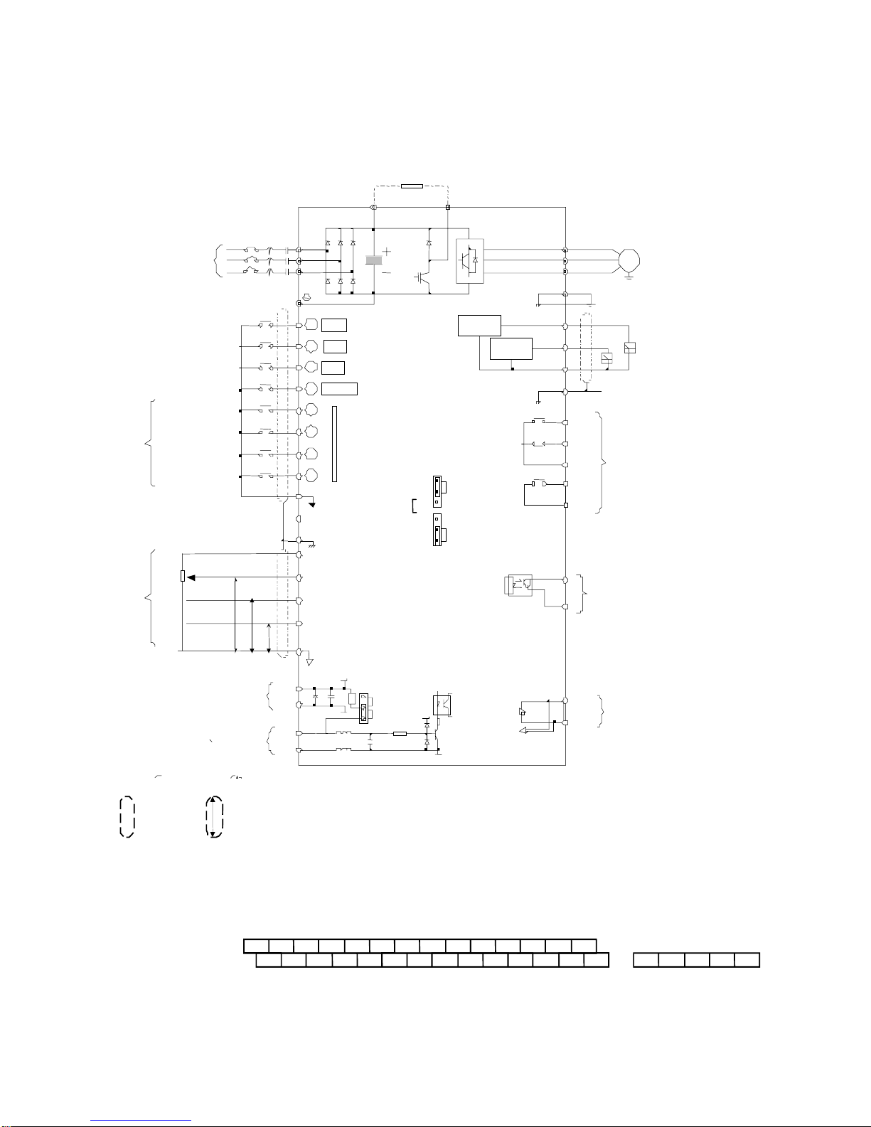
■Standard Connection Diagram
The standard connection diagram of MA7200 is shown in Fig. 2. The sign ◎
indicates the main circuit terminal and the sign ○indicates control circuit terminal. The
terminal function and arrangement are summarized in Table 1 and Table 2. There are
three types of control board, the terminal arrangement is shown as below.
(A) For Compact Size Type 230V : 1-2HP, 460V : 1-2HP (NEMA4 are the same)
•MA7200-2001/2-N1 •MA7200-4001/2-N1
IP12
OPEN
PULL UP
B1/P B2
Braking Resistor
MC
NFB
SC (DG)
Shield Sheath
E
GND Analog signal Common
Digital signal Common
+12V Power Supply for
Speed Ref.
(+12V, 20 mA)
AIN Master Speed Ref.
VIN Master Speed Ref. 0 ~ 10V, (20k
Ω
)
AUX Multi-Funtion
Analog Input
0 ~ 10V, (20k
Ω
)
2k
Ω
1/2W
FWD/STOP
REV/STOP
External Fault
Multi-Step
Speed Ref.1
Jogging
Acc. & Dec.
Switch
Factory Preset
P
P
P
0 ~ +10V
4 ~ 20 mA
0 ~ +10V
0V
4 ~ 20 mA, (250
Ω
)
AO1
V/T2
W/T3
IM
Grounding Lead
(<100
Ω
)
GND
AO2
Analog
Output 1
RA
RB
RC
Multi-Function Contact Output
250V AC, <1A
30V DC, <1A
DO1
DOG
DO2 Multi-Function Output 1, 2
(Open Collector 48V, 50mA)
RS-485 Port
S(+)
S(-)
Analog Monitor 1, 2
(DC 0 ~ 10 V)
U/T1
Main Ckt
Power Supply
R/L1
S/L2
T/L3
Multi-Step
Speed Red.2
Analog
Output 2
E
EXTERNAL FREQUENCY
COMMAND
Fault RESET
(*1)
(*2) The terminal arrangement
(*3) The control board code No. : 4P101C0040001
(*4) The CN2 wire code No. : 4H339D0250001
P
Shield
Wire
Shielded
Twisted Wire
SC 1357
VIN AIN AUX DO1 DO2 DOG
E2468
+12V
GND AO1 AO2
ES(+)
S(-)
GND
RA RB RC
A(+)
A(-)
PG INPUT
(A PHASE)
IP12
IG12
EXTERNAL PG
DC VOLTAGE
1
2
3
4
CN2
FWD ("Close":FWD)
REV ("Close":REV)
Eb
RESET
Multi-Function
Contact Input
2
3
4
5
6
7
8
1
(*1)
TP1
(*4)
Fig. 2-a Standard connection diagram
(*4)Pulse Input Frequency Command
1-10
(B) 230V : 3-40HP, 460V : 3-75HP (NEMA4 to 20HP)
yMA7200-2003-N1 yMA7200-4003-N1
through through
MA7200-2040-N1 MA7200-4075-N1
IP12
OPEN
PULL UP
B1/P B2
Braking Resistor
MCNFB
24VG
Shield Sheath
E
(Sink Common)
FW D/STOP
REV/STOP
External Fault
Multi-Step
Speed Ref.1
Jogging
Acc. & Dec.
Switch
Factory Preset
V/T2
W/T3 IM
U/T1
Main Ckt
Power Supply R/L1
S/L2
T/L3
Multi-Step
Speed Red.2
Fault RESET
GND Analog signal Common
+12V or -12V Power Supply
for
Speed Ref.
(±12V, 20 mA)
AIN Master Speed Ref.
VIN Master Speed Ref. 0 ~ 10V & -10V~10V
, (20kΩ)
AUX Multi-Function
Analog Input
0 ~ 10V, (20k
Ω
)
2k
Ω
1/2W
PP
P
-10V ~ +10V
4 ~ 20 mA
0 ~ +10V
0V
4 ~ 20 mA, (250
Ω
)
EXTERNAL FREQUENCY
COMMAND
24V
(Source Common)
AO1
Grounding Lead
(<100
Ω
)
GND
AO2
Analog
Output 1
Analog Monitor 1, 2
(DC 0 ~ 10 V)
Analog
Output 2
E
Multi-Function Contact Output
250V AC, <1A
30V DC, <1A
R1A
R1B
R1C
R2A
R2C
RS-485 Port
S(+)
S(-)
Multi-Function Output 1
(
Open Collector 48V, 50mA
)
DO1
DOG
FW D ("Close":FWD)
REV ("Close":REV)
Eb
RESET
Multi-Function
Contact Input
2
3
4
5
6
7
8
1
(*1)
(
*2
)
The terminal can be set as SINK or SOURCE t
yp
e in
p
ut interface, when settin
g
as sink t
yp
e
input, the short jumper of TP2 must be set to SINK position, and set to SOURCE position for source type input.
(*3) The terminal arrangement
(*4) The control board code No. : 4P101C0060002
P
Shield
Wire Shielded
Twisted Wire
24VG 135 7 AUXVIN AIN24V DO1 DOG IP12 A(+) A(-)
E24 6 8 +12VGND AO1 AO2 EIG12 S(+) S(-)GND R2A R2C R1A R1B R1C
18
~1 8
~
(*1)
A(+)
A(-)
PG INPUT
(A PHASE)
IP12
IG12
EXTERNAL PG
DC VOLTAGE
(* 2)
TP2 :
TP2 : SINK
SOURCE
TP1
Fig. 2-b Standard connection diagram
Fig. 2-b Standard connection diagram
TP2
SINK
(
20
K
Ω
)
(*4)Pulse Input Frequency Command
(*1)
(*2) The term inal
c
and
j
can be set
as SINK or
S OURCE
type input interface, when settingc
~j
as sink type input, the short jum per of TP2
must be set to SIN K posit
ion, and set to SOURCE position fo r source type input.
P
Shield Wire Shield e Twisted
Wire
( * 5) The term inal arrangem ent
( * 6) The contro l board code No.
:
4P101C 0130001
24VG 1357VIN AIN AUX DO1
24V DOG IP12 A(+) A(-)
E2468+12V -
12V AO1 AO2 EIG12 S(+) S(-)
GND R2A R2C R1A R1B R1C
(
*3)
(*4)
VIN Ref. can be set in two input methods as 0~10V or -10~+10V
The term inal A(+), A (-) can be the output term inal of Pulse Input Frequency Command, and the jum per of TP1 must be set to OPEN position.
Pulse Input Frequency Command: 0~32K H z, 3~12V High torsion, input resistor 2.7K Ω

1-11
1.5 Description of terminal function
Table 1 Main circuit terminals
Terminal 230V:1~20HP, 460V:1~20HP 230V:25~40HP, 460V:25~75HP
R/L1
S/L2
T/L3
Main circuit input power supply
(For single phase power supply, please use R/L1, S/L2 as input terminal)
B1/P
B2 -
Θ
B1/P, B2: External braking resistor
B1/P, Θ: DC power supply input
⊕-
• ⊕ - \: DC power supply or
braking unit
B2/R Unused -
U/T1
V/T2
W/T3
Inverter output
EGrounding lead (3rd type grounding)
■Terminal block configuration
․230V : 1 ~ 2HP ․ 460V : 1 ~ 2HP
R/L1 S/L2 T/L3
B1/P
U/T1 V/T2
W
/
T3
B2
R/L1 S/L2 T/L3
B1/P
U/T1 V/T2
W
/
T3
B2
J2
J4
․230V : 3~5HP
R
/L1
S
/L2
T
/L3
E
B1/P
B1/R
B2
U
/T1
V
/T2
Power In Dynamic Brake
To Moto r
W
/T3
CHARGE
․460V : 3~5HP
R
/L1
S
/L2
T
/L3
E
B1/P
B2
U
/T1
V
/T2
Power In Dynamic Brake
To Moto r
W
/T3
CHARGE
․230V/460V : 7.5~10HP
R
/L1
S
/L2
T
/L3
E
B1/P
B1/R
B2
Power In Dynamic Brake
CHARGE
U
/T1
V
/T2
W
/T3
E
To Motor
․230V/460V : 15~20HP ․ 230V : 25~40HP, 460V : 25~75HP
R/L1 S/L2 T/L3 U/T1 V/T2
W
/
T3B1/P B2
R/L1 S/L2 T/L3 U/T1 V/T2
W
/T3

1-12
Table 2 Control circuit terminals
Terminal Functions
1(DI1) Forward Operation – Stop Signal
2(DI2) Reverse Operation – Stop Signal
3(DI3) External Fault Input
4(DI4) Fault Reset
5(DI5)
6(DI6)
7(DI7)
8(DI8)
Multifunction Input Terminal: 3-Wire Operation, Load/Remote Control, Multi-Speed Select,
FWD/REV Select, ACC/DEC Choice, ACC/DEC Halting, Base Block, Overheat Warn, PID
Control, DC Braking, Speed Search, Up/Down Function, PG Feedback Control, External Fault,
Timer function, Multifunction Analog Input Setting
SC(DG)
(24VG)
Digital Signal Ground
Sink Common Point (Locate the short jumper of TP2 in SINK position)
24V Source Common Point (Locate the short jumper of TP2 in SOURCE position)
E Connection to Shield Signal Lead (Frame Ground)
+15V(+12V) DC voltage for External Device
-12V Only support by the board 4P101C01301
VIN Master speed Voltage Reference (0~10V) (4P101C01301 support –10V~10V input)
AIN Master speed Current Reference (4~20mA)
AUX
Auxiliary Analog Input:
Auxiliary frequency Command, Frequency Gain, Frequency Bias, Overtorque Detection, Output
Voltage Bias, ACC/DEC Ramp, DC-Brake Current, Stall Prevention Current Level during
Running Mode, PID Control, Lower-Bound of Frequency Command, Frequency-Jump-4, etc
GND Analog Signal Common
IP12
IG12 External Power Source For PG Feedback Use
A(+)
A(-) Signal Input of PG (also can be the input terminal of Pulse Input Frequency Command)
AO1
AO2
Analog Multifunction Output Port:
Frequency Commend, Output Frequency, Output Current, Output Voltage, DC Voltage, PID
Controlled Value, Analog Command Input of VIN, AIN or AUX.(Below 2mA)
GND Common Lead for Analog Port
RA(R1A) Relay Contact Output A
RB(R1B) Relay Contact Output B
RC(R1C) Relay Contact Common
Same function as terminal DO1,
DO2
DO1
DO2
(
R2A
R2B
)
Digital Multi-Function (Open Collector) Output “1”, “2” Terminals:
During-Running, Zero-speed, Agreed-frequency, Agree-frequency-setting, Frequency-Output,
Inverter-Operation-Ready, Undervoltage-Detection, Base-Block Output, Run Source, Frequency
command, Overtorque Detection, Frequency Command Invalid, Fault, Undervoltage, Overheat,
Motor Overload, Inverter Overload, During-Retry, Communication-Fault, Timer-Function-Output
DOG Common Terminal (of Open Collector Transistor)
S(+)
S(-) RS-485 Port
Caution
• Use the control circuit terminals VIN, AIN according the setting of Sn-24.
• The MAX. Output current at terminal (+15V or +12V) is 20mA.
• The multi-function analog output terminals AO1, AO2 is a dedicated output for a frequency meter, ammeter,
etc. Do not use these 2 analog outputs for feedback control or any other control purpose.

1-13
1.6 Main Circuit Wiring Diagram
Main Circuit Wiring Diagram of MA7200:
1. 230V/460V : 1~20HP
2. 230V : 25HP 460V : 25~30HP
3. 230V : 30~40HP 460V : 40~75HP

1-14
1.7 Wiring main circuit and notice
■Main circuit wiring
The non-fusible-breaker (NFB) should be installed between the AC source and the
R/L1-S/L2-T/L3 input terminal of MA7200 inverter. The user can make his own decision
of installing electromagnetic contactor block (MCB) or not. To protect against the false
triggering of leakage-current, the user should install a leakage current breaker with
amperage sensitivity≧200mA and operation time≧0.1 sec.
Table 3 230V and 460V class applicable wire size and connector
MA7200 model Wire size (mm2)
Power
supply
Applicable
Power Rating
(HP)*1
Rated
KVA
Rated
current
(A)
Main
circuit*2
Ground
connection
wire E (G)
Control
wire*3
NFB*4 MCB*4
1HP 2 4.8 2~5.5 2~5.5 0.5~2TO-50EC(15A) CN-11
2HP 2.7 6.4 2~5.5 3.5~5.5 0.5~2TO-50EC(20A) CN-11
230V
1Φ/3Φ3HP 4 9.6 3.5~5.5 3.5~5.5 0.5~2TO-50EC(20A) CN-11
5.4HP 7.5 17.5 5.5 5.5 0.5~2TO-50EC(30A) CN-16
7.5HP 10.1 24 8 5.5~80.5~2TO-100S(50A) CN-18
10HP 13.7 32 8 5.5~80.5~2TO-100S(60A) CN-25
15HP 20.6 48 14 8 0.5~2TO-100S(100A) CN-50
20HP 27.4 64 22 8 0.5~2TO-100S(100A) CN-65
25HP 34 80 22 14 0.5~2TO-225S(150A) CN-80
30HP 41 96 38 14 0.5~2TO-225S(175A) CN-100
230V
3 Φ
40HP 54 130 60 22 0.5~2TO-225S(175A) CN-125
1HP 2.2 2.6 2~5.5 2~5.5 0.5~2TO-50EC(15A) CN-11
2HP 3.4 4 2~5.5 3.5~5.5 0.5~2TO-50EC(15A) CN-11
3HP 4.1 4.8 2~5.5 3.5~5.5 0.5~2TO-50EC(15A) CN-11
5.4HP 7.5 8.7 2~5.5 3.5~5.5 0.5~2TO-50EC(15A) CN-18
7.5HP 10.3 12 3~5.5 3.5~5.5 0.5~2TO-50EC(20A) CN-18
10HP 12.3 15 5.5 5.5 0.5~2TO-50EC(30A) CN-25
15HP 20.6 24 8 8 0.5~2TO-50EC(30A) CN-25
20HP 27.4 32 8 8 0.5~2TO-100S(50A) CN-35
25HP 34 40 8 8 0.5~2TO-100S(75A) CN-50
30HP 41 48 14 8 0.5~2TO-100S(100A) CN-50
40HP 54 64 22 8 0.5~2TO-100S(100A) CN-65
50HP 68 80 22 14 0.5~2TO-125S(125A) CN-80
60HP 82 96 38 14 0.5~2TO-225S(175A) CN-100
460V
3Φ
75HP 110 128 60 22 0.5~2TO-225S(175A) CN-125
*1 : It is assumed constant torque load.
*2 : The main circuit has terminals of R/L1, S/L2, T/L3, U/T1, V/T2, W/T3, B1/P, B2/R, B2,Θ.
*3 : The control wire is the wire led to the pin terminals of control board.
*4 : In Table 3, the specified Part No. of NFB and MC are the item No. of the products of TECO. The
customer can use the same rating of similar products from other sources. To decrease the noise
interference, be sure to add R-C surge suppressor (R: 10Ω/5W, C: 0.1µF/1000VDC) at the 2
terminals of coils of electromagnetic contactor.

1-15
■External circuit wiring precaution:
(A) Control circuit wiring:
(1) Separate the control circuit wiring from main circuit wiring (R/L1, S/L2, T/L3, U/T1,
V/T2, W/T3) and other high-power lines to avoid noise interruption.
(2) Separate the wiring for control circuit terminals RA-RB-RC (R1A-R2B-R2C) (contact
output) from wiring for terminals c~j, A01, A02, GND, DO1, DO2 , DOG 15V(or
+12V, -12V), VIN, AIN, AUX, GND, IP12, IG12, A (+), A (-), S(+) and S(-).
(3) Use the twisted-pair or shielded twisted-pair cables for control circuits to prevent
operating faults. Process the cable ends as shown in Fig. 3. The max. wiring distance
should not exceed 50 meter.
Connect to shield
sheath terminal E
Shield sheath Armor
Do not
connect here
Insulated with tape
Fig. 3. Processing the ends of twisted-pair cables
When the digital multi-function output terminals connect serially to an external relay, an
anti-parallel freewheeling diode should be applied at both ends of relay, as shown below.
free-wheeling diode
(100V, >100mA)
48V max.
50 mA max.
7200MA external wiring circuit
Fig. 4. The Optical-couplers connect to external inductive load
(B) Wiring the main circuit terminals:
(1) Input power supply can be connected to any terminal R/L1, S/L2 or T/L3 on the
terminal block. The phase sequence of input power supply is irrelevant to the phase
sequence.
(2) Never connect the AC power source to the output terminals U/T1, V/T2 and. W/T3.
(3) Connect the output terminals U/T1, V/T2, W/T3 to motor lead wires U/T1, V/T2, and
W/T3, respectively.
(4) Check that the motor rotates forward with the forward run source. Switch over any 2
of the output terminals to each other and reconnect if the motor rotates in reverse with
the forward run source.
(5) Never connect a phase advancing capacitor or LC/RC noise filter to an output circuit.
MA7200

1-16
(C) GROUNDING :
(1) Always use the ground terminal (E) with a ground resistance of less than 100Ω.
(2) Do not share the ground wire with other devices, such as welding machines or
power tools.
(3) Always use a ground wire that complies with the technical standards on electrical
equipment and minimize the length of ground wire.
(4) When using more than one inverter, be careful not to loop the ground wire, as
shown below.
(a) OK (b) OK (c) NO
Fig. 5. MA7200 ground winding
•Determine the wire size for the main circuit so that the line voltage drop is within
2% of the rated voltage. (If there is the possibility of excessive voltage drop, use a
larger wire suitable to the required length)
•Installing an AC reactor
If the inverter is connected to a large-capacity power source (600kVA or more),
install an optional AC reactor on the input side of the inverter. This also improves
the power factor on the power supply side.
•If the cable between the inverter and the motor is long, the high-frequency
leakage current will increase, causing the inverter output current to increase as
well. This may affect peripheral devices. To prevent this, adjust the carrier
frequency, as shown below:
Cable length < 100ft. 100-165ft. 166-328ft.
>
329ft.
Carrier frequency
(Cn-34)
15kHz max
(Cn-34=6)
10kHz max
(Cn-34=4)
5kHz max
(Cn-34=2)
2.5kHz
(Cn-34=1)
Table of contents
Other TECO-Westinghouse Motor Inverter manuals


Popular Inverter manuals by other brands


BARRON
BARRON EXITRONIX Tucson Micro Series installation instructions

Baumer
Baumer HUBNER TDP 0,2 Series Mounting and operating instructions

electroil
electroil ITTPD11W-RS-BC Operation and Maintenance Handbook

Silicon Solar
Silicon Solar TPS555-1230 instruction manual

Mission Critical
Mission Critical Xantrex Freedom SW-RVC owner's guide

HP
HP 3312A Operating and service manual


