Tsuruga Electric Corporation 3566 User manual

I-01529
TSURUGAELECTRIC CORPORATION
MODEL 3566
Digital AC mΩMeter
Instruction Manual

2
Contents
Page
1.Preface …………………………………………………………………………………...…………....….. 3
1.1 Preparations prior to use ……………………………………………………..…….………………. 3
1.1.1 Inspection …………………………………………………………….…………………… 3
1.1.2 Storage ………………………………………………………………….……………….… 3
1.2 Confirmation prior to use ………………………………………………………..………………… 3
1.2.1 Power supply …………………………………………………………….………………… 3
1.2.2 Power supply cable …………………………………………….…………………………. 3
1.2.3 Replacement of fuse ………………………………………………………………………. 3
2.Name of Parts …………………………………………………………………………….……………… 4
2.1 Front panel ……………………………………………………………….……………..………….. 4
2.2 Rear panel ………………………………………………………………….………………………. 6
3.Operation ……………………………………………………………………….……………………….. 7
3.1. Power supply ………………………………………………………………………………………. 7
3.2 Connection of measuring terminals …………………………………………………….………….. 7
3.3 Cautions for measurement ………………………………………………….………………..…….. 8
3.3.1 When overlaying the DC voltage………………………….……….………………..…….. 8
3.3.2 Others……………………………………………………….………………………..…….. 8
3.4 Connection of analog output……...………………………………………..……………………….. 8
3.5 Key-lock ……………………………………………………………….…….…………..…………. 8
3.6 Changeover of display ……………………………………………….……….…………..…….….. 9
3.6.1 Selection of display mode ……………………………………………………….………… 9
3.6.2 Selection of ratio display………………………………………………………….……….. 10
3.7 Changeover of resistance range …………………………………….…………………….……….. 11
3.8 Changeover of voltage range ...…………….………………………………….………….………. 11
3.9 Zero adjustment …………………………………………………………………………………… 12
3.9.1 Key operation …………..……………………………………………….………….……. 12
3.9.2 Remote operation ……..……………………………………………………………..……. 12
3.10 Selection of sampling rate …………………………………………………………………………. 12
3.11 Setting of power source frequency ……………………………………………………….…..…… 13
3.12 Setting of voltage limiter ………….……………………………………………………………….. 13
3.13 Comparator action ………………………………………………………………………….……… 14
3.13.1 Conditions of comparison ……………………………………………..………………..... 14
3.13.2 Comparator output …………………………………………………………………….…. 14
3.13.3 Setting method ………………………….………………………………….….…………. 15
3.14 Buzzer ………………………………………………………………………………………..…… 18
3.14.1 Setting method ……………………………………………………………………………. 18
3.15 Manual mode ……………………………………………………………………….…………..… 19
3.16 Memory mode ……………………………………………………………………………………. 19
3.16.1 Selection of memory …………………………………………………………..………… 19
3.17 Setting of memory ………..…………………………………………………………..………..…. 20
3.18 Detection of disconnection and self-check ………………………………………………………. 22
3.18.1 Operation ………………………………………………………………………………… 22
4.Remote control ………………………………………………………………………….………….….. 23
4.1 Remote connector …………………………………………………………………………..…….. 23
4.1.1 Pin operation ……………………………………………………………………………….. 23
4.1.2 Remote operation of memory mode ………………………………………………….……. 24
4.1.3 Timing chart of remote control …………………………………………………………….. 25
4.2 Remote control (input and output terminal blocks) ……………………………………….……… 27
5.Setting method …………………………………………………………………………………………. 28
5.1 Resistance measurement …………………………………………………………………………... 28
5.2 Ratio display function ….………………………………………………………………………….. 29
5.2.1 Setting of referential resistance value and deviation ……………………………………….. 30
5.3 Voltage measurement …………….………………………………………………………………... 31
5.4 Character display ………………………………………………………………………………….. 31
6.Use in panel-mount ………………………………………………………………………………….…. 32
6.1 Assembly drawing …………………………………………………………………………..……. 32
6.2 External dimensions when fitted with panel-mount bracket ……………………………………… 32
7.Calibration ……………….…………………………………………………………………………….. 33
7.1 Things to prepare …………………………………………………………………………….…… 33
7.2 Calibration ………………………………………………………………………………………… 33
7.2.1 Calibration of resistance measurement …………………………………..…………….…... 33
7.2.2 Calibration of voltage measurement …………………………………………………….…. 34
7.2.3 Calibration of analog output ………………………………………………………….…….. 34
8.Specifications ………………………………………………..………………………………………….. 35
8.1 Model name ……………………………………………………………………………………….. 35
8.2 Measuring range and accuracy …………………………………………………………..…….….. 35
8.3 General specifications …………………………………………………………………………..… 36
8.4 Table of initial setting (at delivery from factory) ……………………………………………….... 37
8.5 External dimensions ………………………………………………………………………………. 37
8.6 Option …………………………………………………………………………………………..… 37
3
1. Preface
We thank you for your purchase of our product. Please take care that this instruction
manual is certainly delivered to the person in charge to operate the product. For proper
use of the product, please carefully read this manual prior to the initial operation.
CAUTION
●To avoid break-down, malfunction or deterioration of life of the product, do
not use it insuch places where:
◆exposed to rain, water drops or direct sunlight.
◆high temperature or humidity, heavy dust or corrosive gas.
◆affected by external noise, radio waves or static electricity.
●Do not use the product dismantling or modifying it.
1.1 ●Preparations prior to use
1.1.1 Inspection
When the meter is delivered, please check whether it conforms to the required
specifications and has not been damaged in transit. If there is any damage on the meter
or it does nor work in conformity with the specifications, please inform us of the model
and product name.
1.1.2 Storage
In case of storing the meter for a long time, store it at the place of low humidity and where
it is not exposed to the direct sunlight.
1.2 ●Confirmation prior to use
1.2.1 Power supply
Use the meter with the power source voltage within 90~250VAC and the frequency
50/60Hz. When connecting the power supply cable, confirm that the power supply
switch is turned OFF.
1.2.2 Power supply cable
The plug of power supply cable connected to the meter is for 100VAC use. When the
meter is used with 200VAC, replace the plug with appropriate one for 200VAC use.
Please connect the power supply cable to the power supply connector on the real panel of
the meter. The plug of power supply cable has 3 pins and the round shape pin in the
center is for grounding. When connecting the meter to the receptacle with an adapter
attached to the plug, be sure to connect the earth wire of the adapter to the external earth
line for grounding.
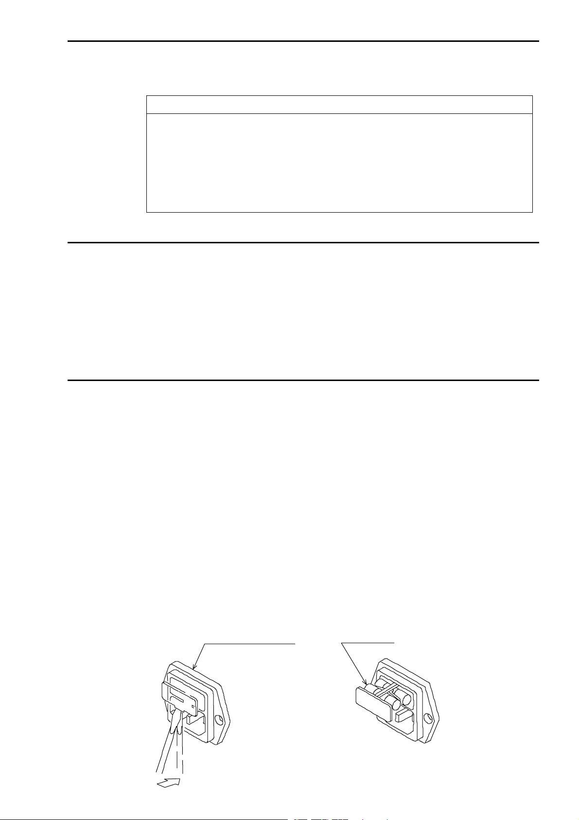
1.2.3 Replacement of fuse
A fuse of 250V/2A for the power source is mounted at the delivery from factory. A
socket of the fuse is incorporated in the input connector of the power supply line. In
advance to connecting the power supply cable, confirm the rate of the fuse, removing the
cap of fuse holder and taking the fuse out. In total two fuses, including a spare one, are
put inside the fuse cap. The fuse on this side (spare fuse) can be removed by pushing it
toward right or left, and the fuse another side downward.
Input connector for
power soutce line Spare fuse
Remove the cap with screwdriver or else.

4
2. Name of parts
2.1 ●Front panel
①Measuring terminals SENSE Hi : Input terminal of resistance measurement and
+terminal of voltage measurement.
SENSE Lo : Input terminal of resistance measurement and
−terminal of voltage measurement.
SOURCE Hi : Current output terminal.
SOURCE Lo : Current output terminal
(Connected to SENSE Lo at the voltage measurement.)
②FUNC key Key to changeover the resistance/ratio display in resistance measurement.
(SET) At ratio display : RATIO lamp is lit up.
At resistance display : OHM lamp is lit up.
(In manual mode, the power source frequency and the limit can be set.)
(In memory mode, the setting of memory can be done.)
③RATE key Key to select a sampling rate.
(MAN’L/MEM) (Key to changeover the memory/manual mode. MAN’L lamp is lit up
in manual mode.)
④0ADJ key Key to ON/OFF the zero-adjust function.
(ONLINE) 0 ADJ lamp is lit up while the zero-adjust function is working.
(On-line key of the GP-IB, RS-485 and RS-232C.)
⑤SHIFT key Blue key becomes effective while the SHIFT lamp is lit up.
(LOCK) While the SHIFT lamp is lit up, it can be turned off by pressing this key.
(The key prohibits the key operation on the front panel. The pressing of
the key for 3 seconds or more allows prohibition or cancellation. During
the prohibition, the LOCK lamp is lit up.)
⑥VEW key Key to select the display mode.
⑦RANGE key Key to select the range of resistance or voltage.
(BUZZER) The resistance range 30mΩ~ 3kΩor AUTO range can be selected.
The voltage range 5V or 50V can be selected.
(Key to enter the setting of buzzer mode and sound volume.)
⑧SEL key Key to changeover the setting items.
COMP SET
⑨key Key used for various setting.
⑩▲key Key used for various setting.
GO
LO
PS
VmΩΩ%kΩ
FM
OHM
V
%Ω
AUTO
No.
COMP SET
(MAN'L/MEM)
MAN'L
±Δ%
V
RANGE
SEL
SHIFT
VEW
SOURCESENSE
MODEL 3566
Lo
Hi
(LOCK)(SET)
(BUZZER)
3Ω
30Ω
300Ω
3kΩ
FL
300mΩ
30mΩ
S
HI
(ONLINE)
FUNC RATE
SHIFT
ONLINE
LOCK
HISET
LOSET
REF
V
RATIO
1
11
12
32 4 5 6 7 8 9 10
0ADJ
0 ADJ
LIM
14 15 16
17
1819 2021
22
23
13

5
⑪MAN’L lamp Lit up in manual mode and turned off in memory mode.
0ADJ lamp Lit up while the zero-adjust is in working.
ONLINE lamp Lit up when remote controlled.
LOCK lamp Lit up while key-locked.
SHIFT lamp Interlocked with SHIFT key. While the lamp is lit up, the key
functions change to those of blue letters ( ).
⑫OHM lamp Lit up in resistance measurement.
RATIO lamp Lit up in ratio display.
⑬LIM lamp Lit up when the limiter of open voltage is not limited to the peak 20mV.
⑭Flamp Displays in blinking when the sampling rate is FAST.
Mlamp Displays in blinking when the sampling rate is MEDIUM.
Slamp Displays in blinking when the sampling rate is SLOW.
(The lamps become steady light during the hold status.)
⑮HI lamp Red LED is lit up when the measured resistance value is at high limit or
above.
GO lamp Green LED is lit up when the resistance measurement is good judgement.
LO lamp Red LED is lit up when the measured resistance value is at low limit or
below.
⑯FL lamp Red LED is lit up when the measured voltage value is at high limit or
above or, low limit or below.
PS lamp Green LED is lit up when the voltage measurement is good judgement.
⑰Unit lamp The unit of the data being indicated on the main display is lit up.
For resistance : kΩ, Ω, mΩ
For ratio : %
For voltage : V
⑱Range lamp In resistance display mode: The measuring range is lit up
The comparator range is lit up in blinking.
In voltage display mode: Turned off.
In resistance voltage display mode: The resistance measuring range is lit
up.
AUTO lamp Lit up in AUTO range measurement.
⑲Main display section The measured values and various characters are displayed.
In Rr mode : The measured resistance value is displayed.
In Vv mode : The measured voltage value is displayed.
In RV mode : The measured resistance value is displayed.
⑳No. display The memory number is displayed in memory mode.
During the setting of buzzer, power source frequency / limit, the
characters being set are displayed.
Ω%lamp Lamp to inform the content of HI SET and LO SET display.
Vlamp Ω%lamp is lit up in Rr mode.
Vlamp is lit up in Vv mode and RV mode.
HI SET display The comparator’s high limit and various characters are displayed.
In Rr mode : The high limit of resistance comparator or the
referential resistance value of ratio measurement is
displayed.
In Vv mode : The voltage comparator’s high limit is displayed.
In RV mode : The voltage side measurement value is displayed.
LO SET display The comparator’s low limit and various characters are displayed.
In Rr mode : The low limit of resistance comparator or the range of
ratio measurement is displayed.
In Vv mode : The voltage comparator’s low limit is displayed.
In RV mode : Turns off.
Note: The (blue letter) keys become effective while the SHIFT lamp is lit up.
6
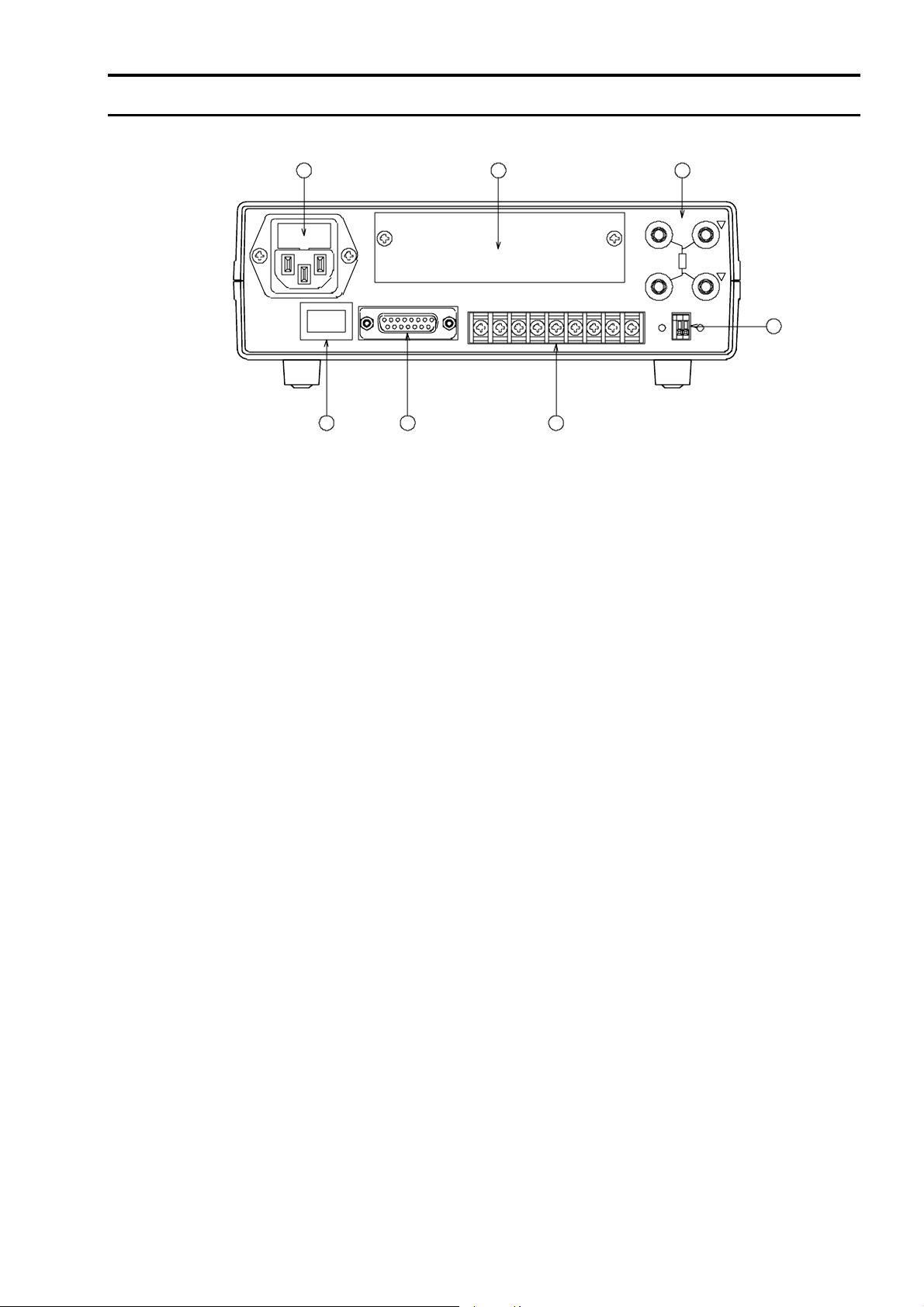
2.2 ●Rear panel
Rear measuring terminals
Respectively common with:
SENSE Hi : (SENSE Hi) on the front panel.
SENSE Lo : (SENSE Lo) on the front panel.
SOURCE Hi : (SOURCE Hi) on the front panel.
SOURCE Lo : (SOURCE Lo) on the front panel.
Power supply The attached power supply connector is to be used.
connector Be sure to use the meter with the specified power source voltage and
frequency.
A fuse of 250V 2A must be used.
Power source switch ON/OFF switch of the power supply.
REMOTE connector Connector for the remote control.
Input and output Terminals for input of hold and reset, and for output of resistance
terminal blocks comparator.
Analog output Terminals to output the DC voltage proportional to the measured value.
terminals ZERO : ZERO volume of the analog output
MAX : MAX volume of the analog output
Inlet for interface Section to fit an optional interface board.
board
25 30
29
282726
GCOM LCOM HCOM HOLDGO LO HI COM RST
FUSE
250V 2A
POWER
AC100V
AC LINE
〜240V
SOURCESENSE
Hi
24
Lo
MAX
ANALOG OUT
ZERO
+-
REMOTE

7
3. Operation
3.1 ●Power supply
After confirming that the power supply switch on the rear panel is turned OFF,
connect the power supply plug into the receptacle and turn ON the power supply
switch. The meter promptly enters into operable condition but it is
recommended to have a pre-heating time for 30 minutes or more. The meter is
provided with the function to retain the parameters, so it stores the status of the
following parameters even when the power supply is turned OFF.
(1) Measuring function, display mode and measuring range.
(2) Set values of comparator (30 program memories).
(3) Key-lock status.
(4) Buzzer status.
(3) Zero-adjust condition.
3.2 ●Connection of measuring terminals
Make a connection to the measuring terminals on the front panel (or rear panel) as the Fig.
3.2.1 shows.
Fig. 3.2.1
Note: If the noise enters the measuring terminals, it may cause the display to widely
fluctuate or the auto-range action to be unstable. Ensure to use the shielded
wire and connect the shield side to the SOURCE Lo.
When the attached clip type lead is used, connect it as the Fig. 3.2.2 shows.
In this case, connect the lead so that the red ▼mark on the meter and the ▼mark of
the red lead, the black ▼mark on the meter and the mark of the black lead coincide with
each other.
Fig. 3.2.2
SOURCE Hi
SENSE Hi
SENSE Lo
SOURCE Lo
Sample to be measured
3566 Lead wire
Shielded wire
Black
Red
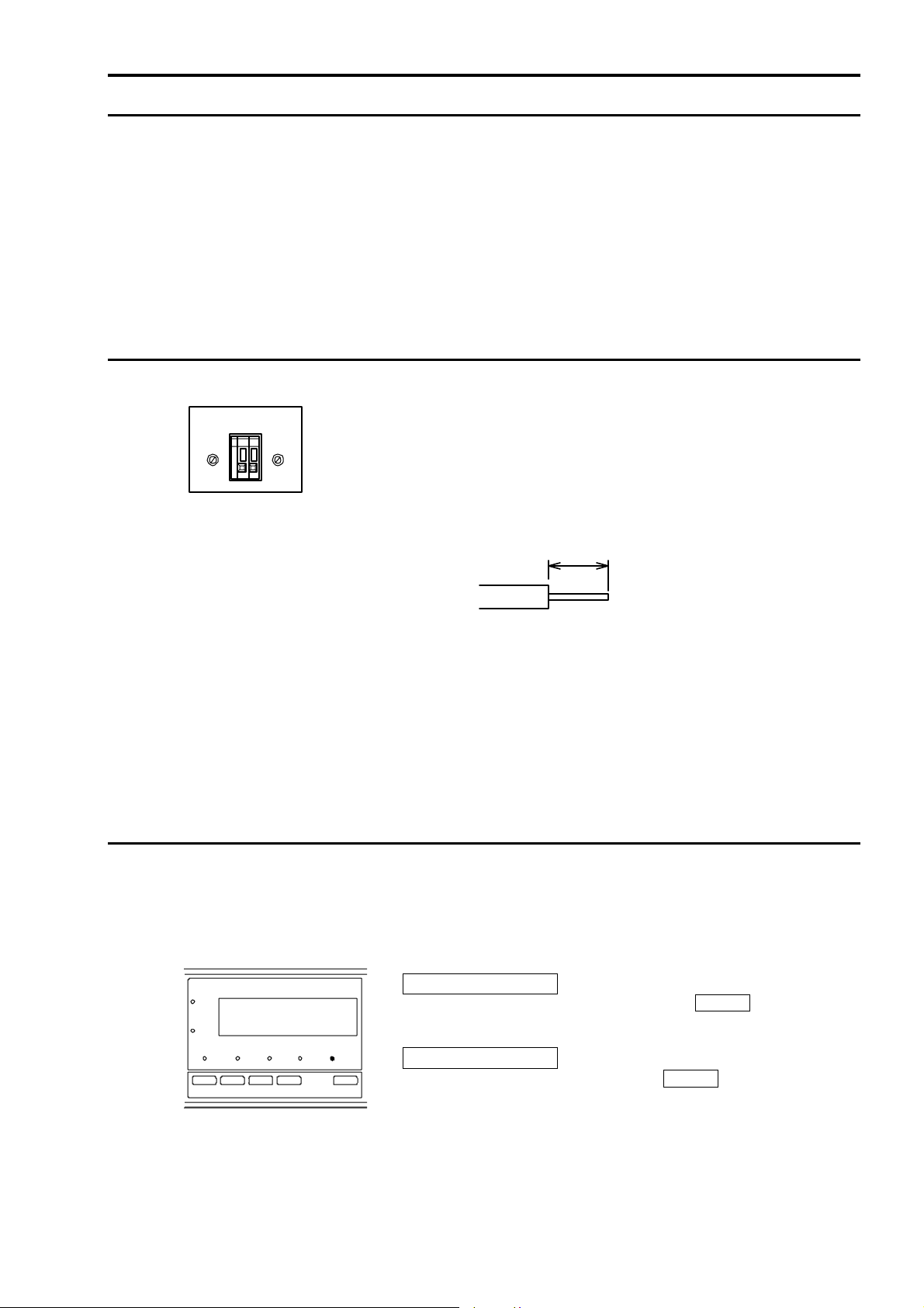
OFF side ON side
8
3.3 ●Cautions for measurement
3.3.1 When overlaying the DC voltage
Apply the voltage 60VDC or less.
After the measurement, the capacitor inside the meter is charged with voltage, so let the
probe short-circuit for a few seconds to discharge it.
3.3.2 Others
A big error may occur when the samples with inductance or capacitance is measured.
If the meter is used near the source of noise (high frequency furnace, high noise power line,
inverter power source etc.), such noise may enter the input line and affect the measurement.
Avoid the use in such a site or keep the sufficient distance from the source of noise.
3.4 ●Connection of analog output
The analog output proportional to the measured resistance value is output.
(The analog data proportional to the resistance value is output even
during the ratio display.)
Make a connection of the cable to the analog output terminal, applying
the cable end treatment as the Fig. 3.4.1 shows.
Push down the release knob with a screwdriver or else and insert the
cable to the terminal.
Length to cut = 9~10mm
Applicable cable: AWG28~AWG32
Fig. 3.4.1
Data output : 0~3VDC
0 display = 0V, 30000 display = 3.000V
Conversion system : D/A conversion system
Resolution : 1mV
Accuracy : Accuracy of resistance measurement + 0.2% F.S.
Output terminal : Screw-less terminal
3.5 ●Key-lock
The key-lock is the function to prohibit the key operation on the front panel so that the
measuring condition is not altered.
While the key-lock is in operation, the LOCK lamp is lit up.
To operate the other keys, cancel the key-lock first.
It is not operable in the ONLINE or HOLD status.
How to key-lock
While the LOCK lamp is turned off, press SHIFT (LOCK) key
for 3 seconds or more.
Reset of key-lock
While the LOCK lamp is lit up, press SHIFT (LOCK) key for 3
seconds or more.
SHIFT
(LOCK)
LOCK
ANALOG OUT
MAX ZERO
+-

9
3.6 ●Changeover of display
The content of display of main display section, HI SET and LOW set can be changed.
The changeover is allowed in the measuring condition. It is not operable in the memory
mode, ONLINE or HOLD status.
The changeover to the ratio display is done with FUNC key.
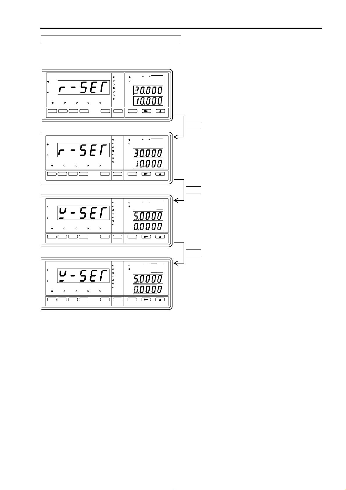
3.6.1 Selection of display mode
Changeover of function
Every time the FUNC key is pressed, the resistance measurement and
the ratio display alternate with each other. Select the resistance
measurement. (No changeover is possible in the Vv mode.)
Changeover of VEW
Every time the
VEW key is pressed, the display changes over.
① To display the resistance value and resistance comparator (Rr mode).
Select the Rr display with VEW key.
Rr mode
② To display the voltage value and voltage comparator (Vv mode).
Select the Vv display with VEW key.
Vv mode
③ To display the resistance and voltage value (RV mode).
Select the RV display with VEW key.
RV mode
GO
Ω
M
OHM
V
%Ω
AUTO
No .
MAN'L
±Δ%
V
VEW
3Ω
30Ω
300Ω
3kΩ
FL
300mΩ
30mΩ
0.ADJ SHIFT LOCK
HI SET
LO SET
REF
V
RATIO
ONLINE
GO PS
V
M
OHM
V
%Ω
AUTO
No .
MAN'L
±Δ%
V
VEW
3Ω
30Ω
300Ω
3kΩ
300mΩ
30mΩ
0.ADJ SHIFT LOCK
HI SET
LO SET
REF
V
RATIO
ONLINE
GO
Ω
M
OHM
V
%Ω
AUTO
No.
MAN'L
±Δ%
V
VEW
3Ω
30Ω
300Ω
3kΩ
FL
300mΩ
30mΩ
0.ADJ SHIFT LOCK
HI SET
LO SET
REF
V
RATIO
ONLINE

10
For the content of each display mode, refer to the Table 3.6.1 below.
Display mode Main display HI SET display LO SET display Ω%
lamp V
lamp
Rr mode Resistance
measurement value
Resistance
comparator
High limit value
Resistance
comparator
Low limit value
(Ratio display) Ratio display Referential resistor Deviation
±⊿%
Lit up Turn
off
Vv mode Voltage
measurement value Voltage comparator
High limit value
Voltage
comparator
Low limit value
Turn
off Lit up
RV mode Resistance
measurement value Voltage measurement
value Turn off Turn
off Lit up
Table 3.6.1
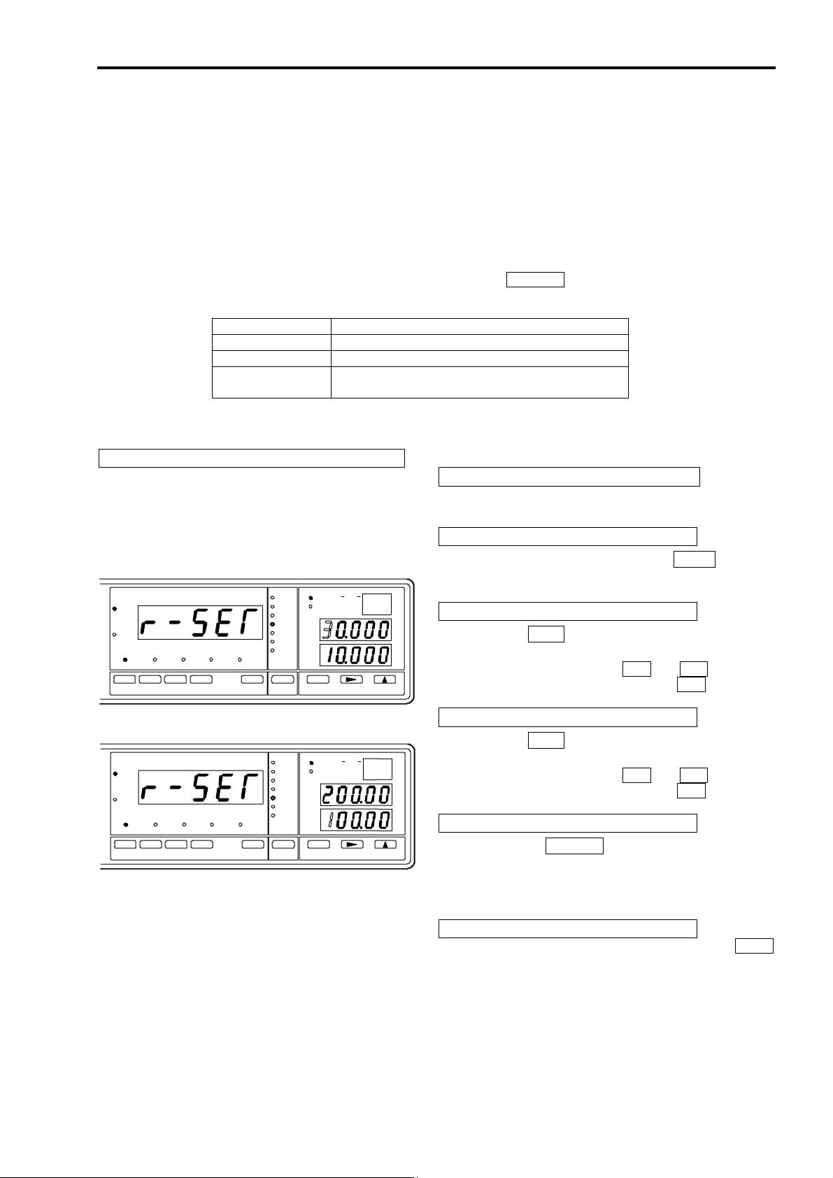
3.6.2 Selection of ratio display
To changeover the ratio display and the resistance display.
Changeover of function
Every time the FUNC key is pressed, the resistance measurement and
the ratio display alternate with each other. In the resistance measurement,
OHM lamp is lit up and the unit of resistance is lit up (one of kΩ, Ωor
mΩ).
In the ratio display, RATIO lamp is lit up and % is lit up.
Ratio display
GO PS
%
OHM
MAN'L
(SET)
S
FUNC
0.ADJ SHIFT
ONLINE
LOCK
RATIO

11
3.7 ●Changeover of resistance range
The measuring range (auto-range or manual range) of the resistance measurement is
selected.
The operation is not allowed in the memory mode, ONLINE or HOLD status.
Selection of resistance measurement
Press the VEW key and select the Rr or RV mode.
Changeover of resistance range
(1) Auto-range
●When the measured resistance value is 35000 (3500) or above, the
range goes up, and when the value is 3000 (300) or less, the range
goes down.
●The AUTO lamp and the lamp of detected range are lit up.
Note: Figures in the brackets are at F sampling rate.
Selection of auto-range
When pressed the
RANGE key, the measuring range changes.
Next to the 3kΩrange, the AUTO lamp is lit up and the range
changes to the auto-range.
Note: When the auto-range is set, both resistance and voltage
measurement change into auto-range action.
(2) Manual range
●The range is fixed range in between 30mΩand 3kΩ.
●The lamp of selected range is lit up.
Selection of manual-range
Every time the RANGE key is pressed, the range lamp changes.
Selected the required range.
3.8 ●Changeover of voltage range
The measuring range of the voltage measurement is selected.
The operation is not allowed in the memory mode, ONLINE or HOLD status.
Selection of voltage measurement
Press the VEW key and select the Vv mode.
Selection of voltage range
(1) Auto-range
●Make the setting of auto-range in the resistance measurement.
The measuring range goes up when the measured voltage value is
50000 (5000) or more, and goes down when the measured value is
1000 (100) or less.
Note: Figures in the brackets are at F sampling rate.
(2) Manual range
●The range is fixed range 5V or 50V.
Selection of range
Every time the RANGE key is pressed, the measuring changes,
and the lit up position of the decimal point changes.
(It can not be changed in the auto-range.)
………. 5V range
………. 50V range
RANGE
AUTO
300Ω
3kΩ
30Ω
300
3Ω
m
Ω
Manual range
Auto-range
30
m
Ω
(
BUZZER
)

12
3.9 ●Zero adjustment
This is the function to suppress the resistance of the tool and so on used in the resistance
measurement.
The data currently measured is memorized in the non-volatile memory as “zero set value”,
and afterwards, the value obtained by deducting the “zero set value” from the measured
value is displayed.
Display value = Measured value −Zero set value
●It works in the resistance display and the resistance voltage display.
●The zero set value works in every range. (It is memorized as the resistance value.)
●When the zero set is made in the higher range, it may cause the over-range in the lower
range.
●Remote operation is possible.
●External control by the interface of GP-IB, RS-232C or RS-485 is possible.
Note: This function is not operable during the HOLD status or setting.
3.9.1 Key operation While the 0 ADJ lamp is turned off, press the 0 ADJ key, the 0 ADJ
lamp is then lit up and enters into the zero adjustment condition.
Cancellation of it can be done by pressing the 0 ADJ key again.
3.9.2 Remote operation
While the 0 ADJ pin and COM of the REMOTE connector on the rear
panel is short-circuited, the 0 ADJ lamp is lit up and the zero adjustment is
in operable condition.
The measured resistance data at the moment when the 0 ADJ pin is short-
circuited is memorized as zero set.
When released the 0 ADJ pin, its working is cancelled.
Note: The zero adjustment action set by the key operation can be
cancelled by making this pin OFF.
3.10 ●Selection of sampling rate
Selection of the sampling range is made by the key operation on the front panel.
The external control by the interface of GP-IB, RS-232C or RS-485 is possible
Note: This function is not operable during the HOLD status or setting.
Key operation
Press the RATE key and the sampling rate changes.
S→M→F→S・・・
Sampling rate
Sampling rate Sampling LED 50Hz 60Hz
S S 1.56 times/sec. 1.88 times/sec.
M M 6.25 times/sec. 7.52 times/sec.
F F 50 times/sec. 60 times/sec.
Ω
OHM
FLSHI
0 ADJ
0ADJ
RATIO
FMS
RATE
13
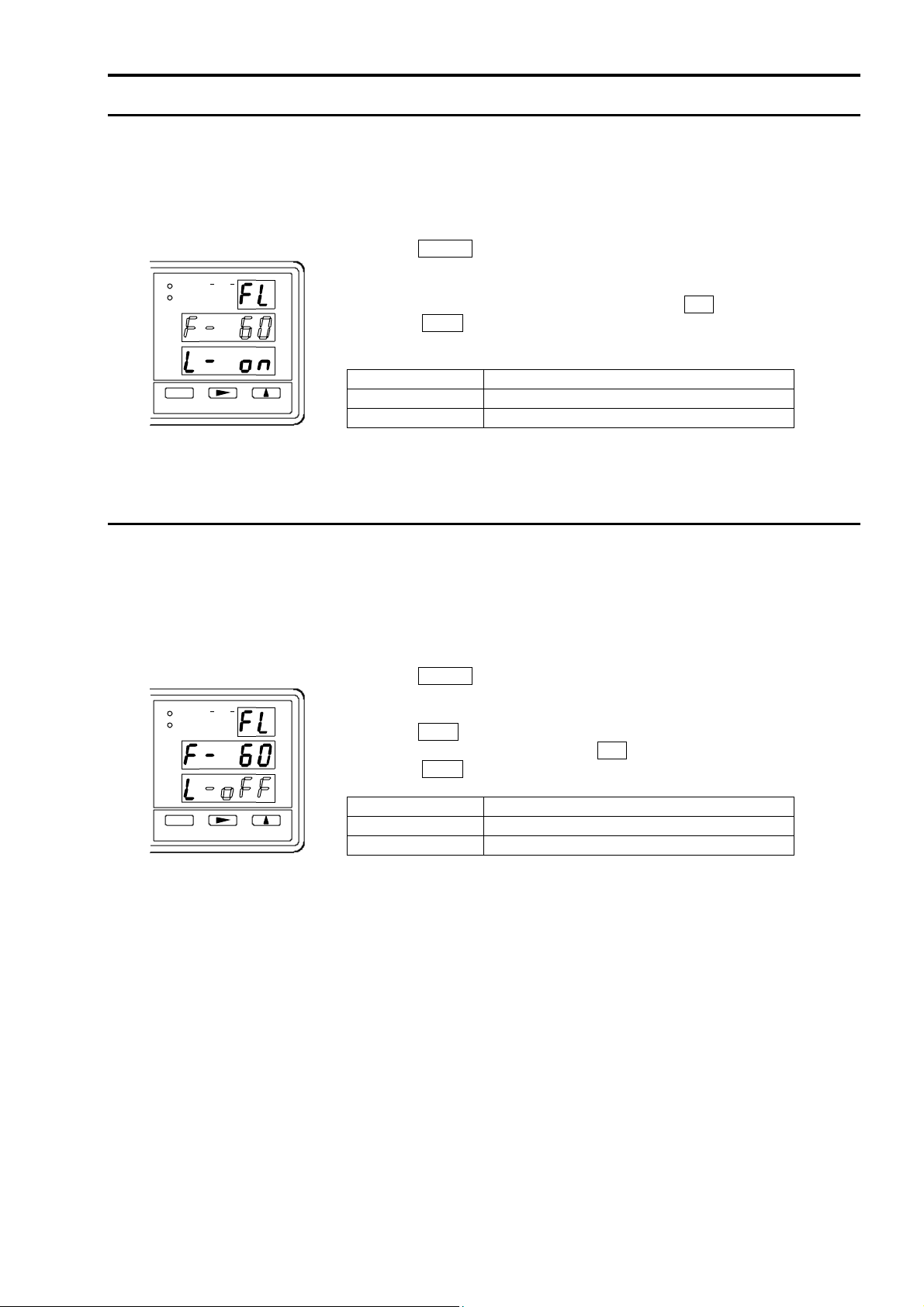
3.11 ●Setting ofpower source frequency
In order to eliminate the affect of inductive voltage to invade the measurement line, the
power source frequency is set.
The operation is not allowed in the memory mode, ONLINE or HOLD status.
When no key operation is made for 5 minutes during the setting, the meter returns to the
measurement.
Press the SHIFT key, and the SHIFT lamp is lit up.
(Enters into the setting of power source frequency and voltage limit.)
Press (SET) key and the HI SET lamp blinks.
Adjust the power source frequency, pressing the ▲key.
When the SEL key is pressed twice, the meter returns to the
measurement.
HI SET display Action
Set to the power source frequency 50Hz
Set to the power source frequency 60Hz
Note: Make sure to set the power source frequency. Otherwise, the accurate
measurement can not be performed.
3.12 ●Setting of voltage limiter
By setting the voltage limiter to ON, it is possible to limit the voltage applied to the
sample to be measured at the peak of 20mV. It protects the destruction of the oxide layer
at the contact of the sample to be measured.
The operation is not allowed in the memory mode, ONLINE or HOLD status.
When no key operation is made for 5 minutes during the setting, the meter returns to the
measurement.
Press the SHIFT key, and the SHIFT lamp is lit up.
(Enters into the setting of power source frequency and voltage limit.)
Press (SET) key and the HI SET lamp blinks.
Press the SEL key, and the LO SET lamp is lit up.
Set the voltage limiter, pressing the ▲key.
When the SEL key is pressed, the meter returns to the measurement.
LO SET display Action
Voltage limit set to OFF
Voltage limit set to ON
V%Ω
No.
±Δ %
V
SEL
HI SET
LO SET
RE F
V
V%Ω
No.
±Δ %
V
SEL
HI SET
LO SET
RE F
V
14
3.13 ●Comparator action
The comparator has two functions – one is the resistance comparator to compare the
resistance values and the other is the voltage comparator to compare the voltage values.
The comparator compares the measured value and high/low limit, and output the
judgement result.
A 30 pairs of the memory high and low limit values per pair can be memorized
(No.1~No.30).
The judgement is output by open collector, simultaneously announcing by buzzer and
lamp. (For the resistance comparator, a relay output can be provided at option.)
The memory can be selected by key operation or through remote connector.
The selection is also possible by the interface of GP-IB, BCD, RS-232C or RS-485.
Note: During the setting of high or low limit value, or calling of the memory, the
sampling is stopped and the output is retained.
3.13.1 Condition of comparison
Resistance comparator
Display value ≧High limit value (HI SET) HI output
High limit value (HI SET) >Display value >Low limit value (LO SET) GO output
Display value ≦Low limit value (LO SET) LO output
Note: The comparator makes the comparison including the range.
Example:
In case that the high limit value is set to 100.00mΩ(300mΩrange), and when
10.00Ωis displayed in the measuring range is 300Ω, the HI output is given.
Voltage comparator
Display value ≧High limit value (HI SET) or
Display value ≦Low limit value (LO SET) FLoutput
High limit value (HI SET) >Display value >Low limit value (LO SET) PS output
3.13.2 Comparator output
Resistance comparator
Open collector output or relay contact output is output at the input/output terminals on the
rear panel.
(Refer to the article 4.2)
Display: HI and LO: Red, GO: Green
Voltage comparator
Open collector output is output at the REMOTE connector on the rear panel.
(Refer to the article 4.1)
Display: FL: Red, PS: Green
15
3.13.3 Setting method
No setting is possible during the ONLINE, when externally controlled by the BCD data
output interface or in the HOLD status.
When no key operation is made for 5 minutes during the setting, the meter returns to the
measurement.
Adjustable range: High limit Resistance : 0~35000
Voltage : -50000~50000
Low limit Resistance : 0~35000
Voltage : -50000~50000
The unit and the decimal point are set with the RANGE key.
The content of the comparator setting is different depending upon the display mode.
Display mode Setting items
Rr mode Resistance comparator, high and low limit
Vv mode Voltage comparator, high and low limit
RV mode Resistance comparator, high and low limit
Voltage comparator, high and low limit
Note: When the setting is for the resistance comparator, in the ratio display mode, the
items to set are deviation (±⊿%).
Setting of resistance comparator (Rr mode) Changeover to manual mode
①(Refer to the article 3.15)
Changeover to resistance display
②Changeover to Rr mode with the VEW key.
(Refer to the article 3.6)
Setting of high limit value
③Press the SEL key.
The highest digit of HI SET display blinks.
Set the numeral with the or ▲ key.
The selected digit blinks with the key.
Setting of low limit value
④Press the SEL key.
The highest digit of LO SET display blinks.
Set the numeral with the or ▲ key.
The selected digit blinks with the key.
Setting of comparator range
⑤Set with the RANGE key
The selected range lamp blinks.
Note: The decimal point automatically changes
depending upon the range.
Finish of the setting
⑥The setting can be finished by pressing the SEL
key during the setting of low limit.
Note-1: When returned to the measurement and, the
measuring range and comparator range are
different, the range lamp of the comparator
range is lit up.
Note-2: When the setting of high or low limit is out
of the range, Err is displayed for a while at
the setting item in question, and then
returns to the setting of high or low limit.
Ω
OHM
V
%Ω
AUTO
No.
MAN'L
±Δ%
V
SELVEW
3Ω
30Ω
300Ω
3kΩ
FL
300mΩ
30mΩ
SHI
0.ADJ SHIFT LOCK
HI SET
LO SET
REF
V
RATIO
ONLINE
Ω
OHM
V
%Ω
AUTO
No.
MAN'L
±Δ%
V
RANGE SEL
3Ω
30Ω
300Ω
3kΩ
FL
300mΩ
30mΩ
SHI
0.ADJ SHIFT LOCK
HI SET
LO SET
REF
V
RATIO
ONLINE

16
Setting of voltage comparator (Vv mode) Changeover to voltage display
①Changeover to Vv mode with the VEW key.
(Refer to the article 3.6)
Setting of high limit value
②Press the SEL key.
The highest digit of HI SET display blinks.
Set the numeral with the or ▲ key.
The selected digit blinks with the key.
Setting of low limit value
③Press the SEL key.
The highest digit of LO SET display blinks.
Set the numeral with the or ▲ key.
The selected digit blinks with the key.
Setting of comparator range
④Set with the RANGE key
The selected range is known by the position of
decimal point being lit up.
5V range : Decimal point at 104is lit up.
50V range : Decimal point at 103is lit up.
Note: The decimal point automatically changes
depending upon the range.
Finish of the setting
⑥The setting can be finished by pressing the SEL
key during the setting of low limit.
Note: When the setting of high or low limit is out
of the range, Err is displayed for a while at
the setting item in question, and then
returns to the setting of high or low limit.
V
OHM
V
%Ω
AUTO
No.
COMP SET
MAN'L
±Δ%
V
RANGE SELVEW
(
BUZZER
)
3Ω
30Ω
300Ω
3kΩ
FL
300mΩ
30mΩ
SHI
0.ADJ SHIFT ONLINE LOCK
HI SET
LO SET
REF
V
RATIO
V
OHM
V
%Ω
AUTO
No.
MAN'L
±Δ%
V
RANGE SELVEW
3Ω
30Ω
300Ω
3kΩ
FL
300mΩ
30mΩ
SHI
0.ADJ SHIFT LOCK
HI SET
LO SET
REF
V
RATIO
ONLINE
17
Setting of resistance voltage comparator (RV mode)
In case of the RV mode, the setting is made sequentially for the resistance comparator and
the voltage comparator.
Setting of resistance comparator
Setting of HI SET
Setting of LO SET
Setting of voltage comparator
Setting of HI SET
Setting of LO SET
SEL key.
Ω
OHM
V
%Ω
AUTO
No.
COMP SET
MAN'L
±Δ%
V
RANGE SELVEW
(
BUZZER
)
3Ω
30Ω
300Ω
3kΩ
FL
300mΩ
30mΩ
SHI
0.ADJ SHIFT LOCK
HI SET
LO SET
REF
V
RATIO
ONLINE
Ω
OHM
V
%Ω
AUTO
No .
COMP SET
MAN'L
±Δ%
V
RANGE SELVEW
(
BUZZER
)
3Ω
30Ω
300Ω
3kΩ
FL
300mΩ
30mΩ
SHI
0.ADJ SHIFT LOCK
HI SET
LO SET
REF
V
RATIO
ONLINE
V
OHM
V
%Ω
AUTO
No.
COMP SET
MAN'L
±Δ%
V
RANGE SELVEW
(
BUZZER
)
3Ω
30Ω
300Ω
3kΩ
FL
300mΩ
30mΩ
SHI
0.ADJ SHIFT ONLINE LOCK
HI SET
LO SET
REF
V
RATIO
V
OHM
V
%Ω
AUTO
No.
COMP SET
MAN'L
±Δ%
V
RANGE SELVEW
(
BUZZER
)
3Ω
30Ω
300Ω
3kΩ
FL
300mΩ
30mΩ
SHI
0.ADJ SHIFT ONLINE LOCK
HI SET
LO SET
REF
V
RATIO
SEL key.
SEL key.
18
3.14 ●Buzzer
The setting of the buzzer is made with the (BUZZER) key on the front panel.
During the setting of buzzer, the sampling is stopped and the comparator output is held.
The setting is not allowed in the memory mode, ONLINE or HOLD status.
When no key operation is made for 5 minutes during the setting, the meter returns to the
measurement.
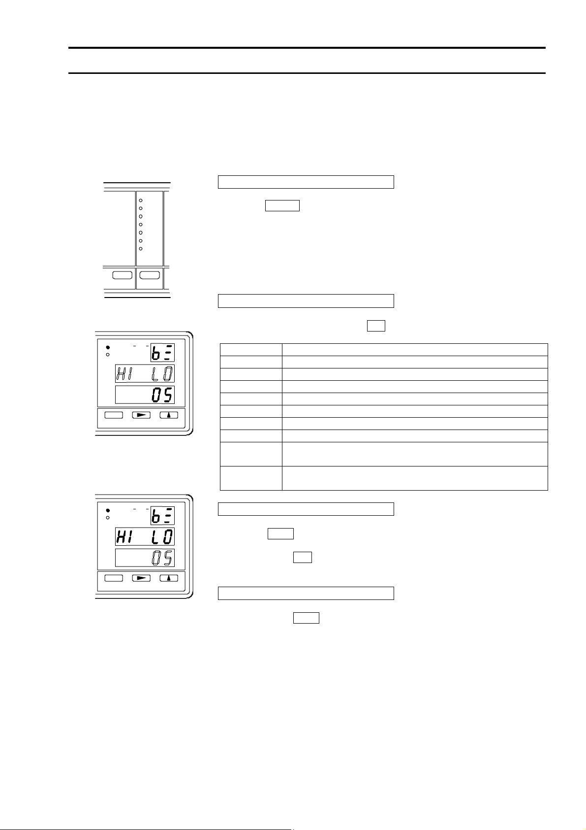
3.14.1 Setting method
Setting of buzzer action
Press the SHIFT key.
TheSHIFT lamp will then light up.
Press the (BUZZER) key.
It changes to the buzzer setting and
is displayed on the No display,
making HI SET blink.
The buzzer action is displayed on the HI SET, and the buzzer sound on the
LO SET.
Selection of buzzer action
Select the buzzer action with the ▲key.
Display Action
Buzzer OFF (buzzer does not sound).
Buzzer sounds when the resistance judgement is GO.
Buzzer sounds when the resistance judgement is HI.
Buzzer sounds when the resistance judgement is LO.
Buzzer sounds when the resistance judgement is HI or LO.
Buzzer sounds when the voltage judgement is PS.
Buzzer sounds when the voltage judgement is FL.
Buzzer sounds when the resistance judgement is GO
and the voltage measurement is PS.
Buzzer sounds when the resistance judgement is HI or LO,
and the voltage judgement is FL.
Adjustment of sound volume
When the SEL key is pressed during the setting of buzzer action, it
becomes the setting of buzzer sound level and the buzzer sounds.
By pressing the ▲key, the sound level and its indication change.
The buzzer sound level is adjustable in 10 steps.
Finish
By pressing the SEL key in the buzzer sound level setting, the buzzer
setting can be finished and the meter returns to the measurement.
V%Ω
No.
±Δ %
V
SEL
HI SET
LO SET
RE F
V
V%Ω
No.
±Δ %
V
SEL
HI SET
LO SET
RE F
V
(BUZZER)
AUTO
300Ω
3kΩ
30Ω
300
3Ω
m
Ω
30
m
Ω
19
3.15 ●Manual mode
In this mode, the changeover of function, measuring range or display mode is possible.
It can not be changed over to the manual mode when the meter is remote controlled and
while the ONLINE is lit up.
Operation
Press the SHIFT key and while the SHIFT lamp is
lit up, changeover the manual mode / memory mode
with the (MAN’L/MEM) key.
During the manual mode, MAN’L lamp is lit up and
the No. display (indication of memory number) turns
off.
3.16 ●Memory mode
In this mode, it is possible to select a memory of the measuring conditions from among 30
memories stored in the meter and to perform the measurement according to the conditions
of the selected memory.
The sampling rate is common setting.
3.16.1 Selection of memory
●Procedures on the front panel
Enter the memory mode
①Press the SHIFT key.
The SHIFT lamp is lit up.
②Press the (MAN’L/MEM) key, and the mode
changes to the memory mode, displaying the
memory number.
The MAN’L lamp turns off.
Call up of memory
③Press the SEL key, then the memory number
changes and the content of the selected memory is
called up. The measurement and judgement are
carried out under the measurement conditions of the
memory called up.
Finish of the memory mode
④Press the SHIFT key.
The SHIFT lamp is lit up.
⑤Press the (MAN’L/MEM) key and the mode
changes to the manual mode, lighting the MAN’L
lamp up.
●Procedures by remote operation Refer to the remote operation of memory mode
(article 4.1.2)
Ω
OHM
V
%Ω
AUTO
No.
(
MAN'L/MEN
)
MAN'L
±Δ%
V
SHIFT
3Ω
30Ω
300Ω
3kΩ
FL
300mΩ
30mΩ
SHI
0.ADJ SHIFT LOCK
HI SET
LO SET
REF
V
RATIO
ONLINE
Ω
OHM
V
%Ω
AUTO
No.
(
MAN'L/MEN
)
MAN'L
±Δ%
V
SELSHIFT
3Ω
30Ω
300Ω
3kΩ
FL
300mΩ
30mΩ
SHI
0.ADJ SHIFT LOCK
HI SET
LO SET
REF
V
RATIO
ONLINE

20
3.17 ●Setting of memory
The setting of memory is made, moving to the memory mode with key operation.
When the memory is selected through the REMOTE connector, the setting is not allowed.
Make the setting of memory with key operation after canceling it.
The items of the memory setting are following 4 items.
●Setting of comparator (resistance/voltage comparator (high and low limit value))
●Display mode (resistance display, voltage display, resistance voltage display)
●Function of resistance measurement (resistance measurement, ratio display)
●Measuring range (resistance measuring range, voltage measuring range)
Note: ●No setting is possible in the hold status.
●No setting is possible while the ONLINE is lit up by the remote operation.
●During the setting, the sampling is stopped and the comparator output is held.
●When no key operation is made for 5 minutes during the setting, the meter
returns to the measurement of the memory mode.
Enter the memory mode
Enter the memory mode with the SHIFT and
(MAN’L/MEM) key. (Refer to the article 3.16)
Setting of memory
Press the SHIFT key, and the SHIFT lamp is lit up.
Press the (SET) key, then the display mode blinks on
the measurement display and the memory number
blinks.
Selection of memory No.
Select the memory No. pressing the ▲key.
Selection of display mode
Select the display mode setting with the VEW key.
The display mode is indicated on the main display
section. The measuring range is displayed together
in the Vv mode.
Setting of ratio display
Make the display to Rr.
Select the ratio display with the FUNC key
When the ratio display is selected, the RATIO lamp is
lit up.
V
OHM
V
%Ω
AUTO
No.
MAN'L
±Δ%
V
VEW
3Ω
30Ω
300Ω
3kΩ
FL
300mΩ
30mΩ
HI
0.ADJ SHIFT LOCK
HI SET
LO SET
REF
V
RATIO
ONLINE
Ω
OHM
V
%Ω
AUTO
No.
MAN'L
±Δ%
V
SHIFT
(SET)
3Ω
30Ω
300Ω
3kΩ
FL
300mΩ
30mΩ
HI
0.ADJ SHIFT LOCK
HI SET
LO SET
REF
V
RATIO
ONLINE
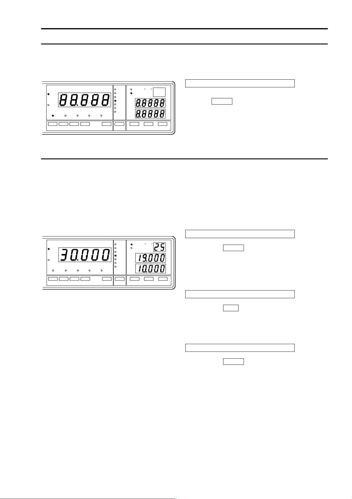
Rr display
Vv display (50V range)
Vv display (5V range)
RV display
OHM
V
%Ω
AUTO
No.
MAN'L
±Δ%
V
3Ω
30Ω
300Ω
3kΩ
FL
300mΩ
30mΩ
HI
0.ADJ SHIFT LOCK
HI SET
LO SET
REF
V
RATIO
ONLINE
%
FUNC
Table of contents
Other Tsuruga Electric Corporation Measuring Instrument manuals

Popular Measuring Instrument manuals by other brands

Powerfix Profi
Powerfix Profi 278296 Operation and safety notes

Test Equipment Depot
Test Equipment Depot GVT-427B user manual

Fieldpiece
Fieldpiece ACH Operator's manual

FLYSURFER
FLYSURFER VIRON3 user manual

GMW
GMW TG uni 1 operating manual

Downeaster
Downeaster Wind & Weather Medallion Series instruction manual

Hanna Instruments
Hanna Instruments HI96725C instruction manual

Nokeval
Nokeval KMR260 quick guide

HOKUYO AUTOMATIC
HOKUYO AUTOMATIC UBG-05LN instruction manual

Fluke
Fluke 96000 Series Operator's manual

Test Products International
Test Products International SP565 user manual

General Sleep
General Sleep Zmachine Insight+ DT-200 Service manual


