Tsurumi Pump TPG4-3000HDX Setup guide

Tsurumi’s Operation, Service, and Repair anual
Introduction
3
WARNING: THIS GENERATOR IS DESIGNED TO GIVE SAFE AND DEPENDABLE SERVICE WHEN
OPERATED ACCORDING TO THE INSTRUCTIONS IN THE TECHNICAL MANUALS PROVIDED
WITH THE GENERATOR.
WARNING: DO NOT OPERATE THE GENERATOR BEFORE YOU HAVE READ AND UNDERSTAND THE
INSTRUCTIONS AND THE ENGINE MANUFACTURER’S MANUAL. FAILURE TO DO SO
COULD RESULT IN PERSONAL INJURY OR EQUIPMENT DAMAGE.
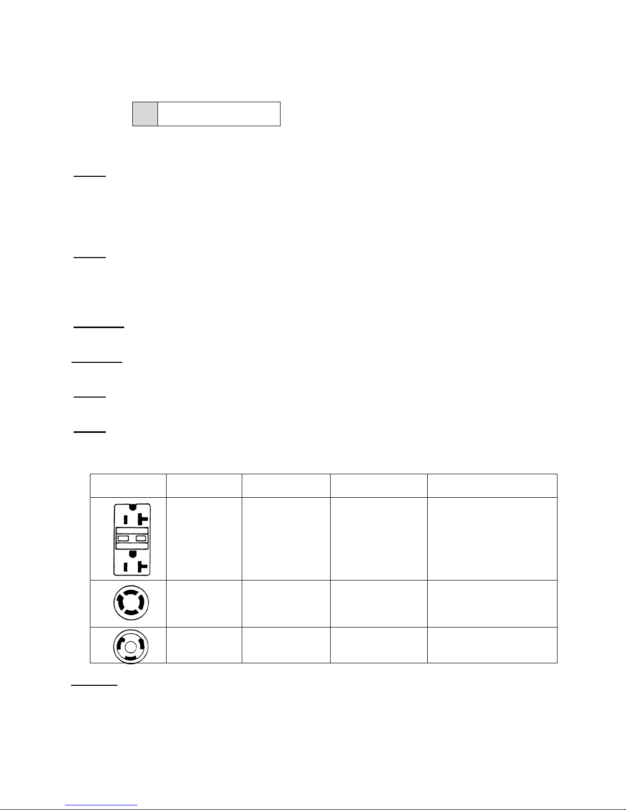
1-3 Placar s
Placards, shown in Figure 1-1 through Figure 1-8 are attached to the portable generator to warn
operating and maintenance personnel of potential hazards, to provide maintenance information,
and to provide generator ratings and capabilities. The large label below is located on the front
panel of the portable generator. The label presents operational Warnings and Cautions for
generator users.
1-4 SAFETY PRECAUTIONS
WARNING: IN ORDER TO ASSURE SAFE AND EFFICIENT OPERATION OF THE GENERATOR,
OPERATOR’S SHOULD READ AND COMPLY WITH THE FOLLOWING SAFETY PRECAUTIONS.
• Do not operate the generator near gasoline or gaseous fuels because of the potential anger from
explosion or fire. Do not fill the fuel tank with fuel while the engine is running. Do not smoke or use open flame
near the fuel tank. Be careful not to spill fuel during refueling. If fuel is spilled, wipe it off and let it dry before
starting the engine.
• Do not place flammable materials near the generator. Be careful not to place fuel, matches, gunpowder, oily
cloths, straw, trash, or any other combustibles near the generator.
• Do not operate the generator insi e a room, cave, tunnel, or other insufficiently ventilate area. Always
operate the generator in a well-ventilated area. The engine may become overheated, and the poisonous carbon
monoxide gas contained in the exhaust gases will endanger human lives.
• Keep the generator at least 1 meter (3 feet) away from any structure or buil ing uring use. When a
generator is located close to a building or nearby equipment, heat and exhaust from the engine will cause the
surrounding temperature to rise. This will degrade the engines cooling efficiency, causing overheating.
• Do not enclose the generator nor cover it with a box. The generator has a built-in, forced-air cooling system,
and may become overheated if it is enclosed.
• Operate the generator on a level surface. It is not necessary to prepare a special foundation for the generator.
However, the generator will vibrate on an irregular surface. Therefore, choose a level place without surface
irregularities.
• Shutoff the generator when moving the generator to another work site. It the generator is tilted or moved
during operation, fuel may spill and/or the generator may tip over, causing a hazardous situation. Proper
lubrication cannot be expected if the generator is operated on a steep incline or slope. In such a case, the piston
may seize; it may seize even if the oil is above the upper level.
• Do not operate in rain or with wet han s. The operator may suffer severe electric shock, if the generator is wet
due to rain or snow. If wet, dry before starting. Do not pour water directly over the generator, nor wash it with water.
• Do not connect the generator to a commercial power line. Connection to a commercial power line may result
in short circuit and damage the generator. When connecting to domestic circuits, install only approved transfer
switches and make sure power and control circuitry meet local electrical code requirements.
• Do not smoke or use other smoking materials (pipes, cigars, etc.) while han ling the battery. The battery
emits flammable hydrogen gas, which can explode if exposed to electrical arcing or open flame. Keep the work
area well ventilated and keep the battery away from open flames/sparks.

Tsurumi’s Operation, Service, and Repair anual
Introduction
3
MADE IN JAPAN
ODEL
RATED OUTPUT
FREQUENCY
VOLTAGE
AX. OUTPUT
60Hz
SERIAL NO. ******
120V
2.2kVA
2.6kVA
TPG4-3000HDX
TSURUMI PORTABLE GENERATOR
TPG4 Fig. 1-1
Using a generator indoors CAN KILL YOU IN INUTES.
Generator exhaust contains carbon monoxide. This is
a poison you cannot see or smell.
Avoid other generator hazards.
READ ANUAL BEFORE USE.
DANGER
NEVER use inside a home
or garage, EVEN IF doors
and windows are open.
Only use OUTSIDE and
far away from windows,
doors, and vents.
TPG4 Fig. 1-3
AIR CLEANER MAINTENANCE
CLEAN ELEMENT EVERY 50 HOURS (EVERY
10 HOURS UNDER DUSTY CONDITIONS).
WASH IN HIGH FLASH-POINT SOLVENT,
SQUEEZE DRY,THEN DIP IN CLEAN ENGINE
OIL AND SQUEEZE OUT EXCESS OIL.
TPG4 Tig. 1-5
■CHECK FOR SPILLED FUEL OR FUEL LEAKS.
STOP ENGINE BEFORE REFUELING.
■INSPECCIONAR PARA COMBUSTIBLE DERRAMADO
O ESCAPE.
PARAR MOTOR ANTES DE ECHAR.
■CONTROLER QU’
REPANDUE SUR L’
ARRETER LE MOTEUR AVANT DE REFAIRE LE PLEIN.
IL N’Y A NI FUITE NI ESSENCE
APPAREIL
^
^
´
TPG4 Fig 1-4
TPG4 Fig. 1-6
TPG4 Fig. 1-2
Figure 1-1: Typical Data Plate
Figure 1-3: Carbon Monoxi e Warning
Figure 1-2: Electrical Warning
Figure 1-4: Fuel Han ling Warning
Figure 1-5: Air Cleaner Maintenance Warning
Figure 1-6: Gasoline/Carbon Monoxi e Warning

Tsurumi’s Operation, Service, and Repair Manual
Operating Instructions
13
3-0 OPERATING INSTRUCTIONS
3-1 Operating Controls
(1) The main operating controls for the generator are, ith a fe exceptions, mounted on the
front panel of the generator.
(2) The controls consist of an ENGINE s itch, an AUTOTHROTTLE s itch, a FULL POWER
s itch, a PILOT light, circuit BREAKER(s), a ground (or earth) post, and electrical
receptacles. The specific controls used in each model are sho n in Figures 3-1 through
3-4.
NOTE: The auto throttle feature is not available on Model TPG4-3000HDX, hich uses a
hand operated throttle lever.
(3) The Model TPG4-7000H-DXE generator is equipped ith a electric starter motor. The
ENGINE s itch in this model is a key-operated, STOP/RUN/START s itch. The spring-
loaded s itch is turned to the right to start the engine, and to the left to shut off the
engine.
(4) The IDLE Control s itch allo s the generator speed to drop to idle speed if there is no
electrical load demand on the generator. When an electrical load is sensed, the idle
function increases the speed of the generator up to operating speed level. When there is
no load, the engine speed returns to idle.
(5) The FULL POWER s itch allo s the generator to provide full rated po er for the loading
appliances and/or tools. When the FULL POWER s itch is set to on, po er ill be
provided to only one 120 Vac receptacle and one 240 Vac receptacle.
(6) The PILOT light provides an indication to the operator that the generator is generating
electricity.
(7) Circuit breakers are provided to protect the generator in the event of a short circuit. The
breakers ill trip hen the circuit load exceeds the breaker’s rated value.
(8) The ground post is used to provide a positive ground for the generator. The post has a
ing-nut to quickly connect a ground ire to the generator.
(9) There are three types of receptacles: one 120 Vac, GFI-protected receptacles (t o on
most models), one t ist-type, 120 Vac receptacle, and one 120 Vac / 240 Vac,
combination receptacle.
3-2 DC Cir uit Controls
(1) The circuitry for DC circuit consists of a 10 Amp fuse, an overload protector, and a reset
s itch. (Model TPG4-7000HDXE only.)
(2) In the event of an overload, the overload protector ill trip the reset s itch located
immediately belo the engine key starter s itch.

Tsurumi’s Operation, Service, and Repair Manual
Operating Instructions
15
IDLE CONTROL SW.
PILOT
AT 120/240V
AT 120 V ONLY
AC 120V/240V
VOLTAGE SELECTOR CIRCUIT BREAKER
GFCI
SW.
ON120V ONLYOFF
AC 120V
ON
OFFTO TAL
20A
TO TA L
20A
30A
120V/240V
CIRCUIT BREAKER
PRES S TO RE SET
CIRCUIT BREAKER
PRES S TO RE SET
CIRCUIT BREAKER
PRES S TO RE SET
OFF
O N
START
ENGINE SW.
STARTER RESET SW.
ON/PUS H
OFF
TEST
TEST
RESET
RESET
Figure 3-3: Model TPG4
44
4-7000HDXE
Starter reset
s itch
Voltage selector
Receptacle 120V
Receptacle 120/240V
Idle control s itch
Engine s itch
Pilot
lamp Circuit breaker
GFCI s itch
Circuit breaker
30A
Circuit breaker
30A
Ground terminal
Circuit breaker
20A
Receptacle 120V

Tsurumi’s Operation, Service, and Repair Manual
Operating Instructions
16
3-3 Grounding Provisions
WARNING: TO PREVENT ELECTRICAL SHOCK FROM FAULTY APPLIANCES, THE PORTABLE
GENERATOR SHOULD BE GROUNDED. CONNECT A LENGTH OF HEAVY WIRE
BETWEEN THE GENERATOR’S GROUND TERMINAL AND EXTERNAL GROUND
SOURCE.
WARNING: CONNECTIONS FOR STANDBY POWER TO A BUILDING’S ELECTRICAL SYSTEM MUST
BE MADE BY A QUALIFIED ELECTRICIAN AND MUST COMPLY WITH ALL APPLICABLE
LAWS AND ELECTRICAL CODES. IMPROPER CONNECTIONS CAN ALLOW
ELECTRICAL CURRENT FROM THE GENERATOR TO BACKFEED INTO THE UTILITY
LINES. SUCH BACKFEED MAY ELECTROCUTE UTILITY COMPANY WORKERS OR
OTHERS WHO CONTACT THE LINES DURING A POWER OUTAGE, AND WHEN UTILITY
POWER IS RESTORED, THE GENERATOR MAY EXPLODE, BURN, OR CAUSE FIRES IN
THE BUILDING’S ELECTRICAL SYSTEM.
A. Electrical Connection Hazards
(1) If you plan to use the portable generator as a backup for the facility’s po er supply, make
sure the connections are made in compliance ith applicable la s and electrical codes.
(1) Connection to a building’s electrical system must be made by a qualified electrician.
(2) Improper connections can allo electrical current from the generator to backfeed into the
utility lines hich may electrocute utility company orkers or others ho contact the lines
during a po er outage. When utility po er is restored, the generator may explode, burn,
or cause fires in the building’s electrical system.
B. Grounding Post Components
(1) The portable generator is fitted ith a grounding post on the right side of the control panel.
The parts that make up the grounding post are sho n in the Replacement Parts section.
The grounding post components and their installation sequence are sho n in more detail
in Figure 3-4.
(2) If the grounding post has been disassembled, reassemble as follo s:
(a) Install star asher (68) on scre (69). Insert scre (69) in backside of panel (46).
(b) Install nut (69) on scre (69) and tighten.
(c) Install cup asher (70) ith sides facing out.
(d) Install flat asher (71), lock asher (72), and ing nut (73).
C. Typical Connection of Ground Wire
(3) Form a loop in ground ire and slip ire bet een flat asher (71) and cup asher (70).
Tighten ing nut (73).
(4) Drive ground rod in ground (or attach to kno n facility ground). Insert free end of ground
ire in clamping scre on rod (or other clamping device) and tighten.

3-6 Che k Engine Fuel
WARNING:
• MAKE SURE YOU REVIEW EACH WARNING IN ORDER TO PREVENT FIRE HAZARD.
• DO NOT REFILL TANK WHILE ENGINE IS RUNNING OR HOT.
• CLOSE FUEL SHUT OFF VALVE BEFORE REFUELING WITH FUEL.
• BE CAREFUL NOT TO GET DUST, DIRT, WATER OR OTHER FOREIGN OBJECTS INTO FUEL.
• WIPE OFF SPILLED FUEL THOROUGHLY BEFORE STARTING ENGINE.
• KEEP AWAY FROM OPEN FLAMES.
• DO NOT USE SMOKING MATERIALS WHEN FILLING THE FUEL TANK.
• DO NOT REFUEL WHILE SMOKING OR NEAR OPEN FLAMES OR OTHER SUCH POTENTIAL
FIRE HAZARDS. OTHERWISE FIRE ACCIDENT MAY OCCUR.
• AVOID REPEATED OR PROLONGED CONTACT WITH SKIN OR BREATHING OF VAPOR.
• KEEP OUT OF REACH OF CHILDREN.
(1) Check fuel level at fuel level gauge (see Figure 3-7).
(2) If fuel level is lo , refill ith unleaded automotive gasoline.
FUEL LEVEL INDICATOR
RESPONDS TO FLOAT LEVEL
TANK EMPTY TANK FULL
(FLOAT LOW) (FLOAT HIGH)
TPG4 FIG 3-7
Figure 3-7: Fuel Gauge Indi ations
Fuel tank apa ity TPG4-3000HDX (4.2 gal.)
TPG4-4500HDX (6.6 gal.)
TPG4-6000HDX (6.6 gal.)
TPG4-7000HDX (6.6 gal.)
TPG4-7000HDXE (6.6 gal.)

3-7 Pre-Start Che ks
WARNING: MAKE SURE YOU REVIEW EACH WARNING IN ORDER TO PREVENT FIRE HAZARD.
WARNING: KEEP AREA CLEAR OF FLAMMABLES OR OTHER HAZARDOUS MATERIALS.
(1) Check the follo ing items before starting the engine.
(a) Fuel leakage from fuel hoses, shutoff valve, auto-throttle unit, engine, and fitttingd
(b) Loose bolts and nuts.
(c) Components for damage or breakage.
(2) Check generator surroundings.
(a) Keep generator at least 3 feet (1 meter) a ay from buildings or other structures.
(b) Operate generator in a dry, ell-ventilated area.
(c) Keep exhaust pipe clear of foreign objects.
(d) Keep generator a ay from open flame.
(e) Keep generator on a stable and level surface.
(f) Do not block generator air vents ith paper or other material.
3-8 Grounding the Generator
WARNING: IMPROPER CONNECTIONS CAN ALLOW ELECTRICAL CURRENT FROM THE
GENERATOR TO BACKFEED INTO THE UTILITY LINES WHICH MAY ELECTROCUTE
UTILITY COMPANY WORKERS OR OTHERS WHO CONTACT THE LINES DURING A
POWER OUTAGE. WHEN UTILITY POWER IS RESTORED, THE GENERATOR MAY
EXPLODE, BURN, OR CAUSE FIRES IN THE BUILDING’S ELECTRICAL SYSTEM.
WARNING: A POTENTIAL ELECTROCUTION HAZARD EXISTS IF THE GENERATOR IS NOT
GROUNDED. A GENERATOR GROUNDING POST IS PROVIDED ON THE CONTROL
PANEL OF THE GENERATOR (REFER TO 3-4 FOR GROUNDING PROVISIONS.)
(1) If you plan to use the portable generator as a backup for the facility’s po er supply during
po er outages, make sure the connections are made in compliance ith applicable la s
and electrical codes.
(5) Connection to a building’s electrical system must be made by a qualified electrician.
(6) Refer to the Removal/Installation section for grounding post installation procedures and
connection of generator ground ire.

3-9 Starting & Stopping the Engine
(1) MANUAL START: (Models TPG4-3000HDX, TPG4-4500HDX, TPG4-6000HDX, and
TPG7-7000HDX.
(a) Before starting the engine, set AC circuit breakers to OFF (the generator may be
hard to start if a load is connected.
(b) Refer to the Honda engine o ner’s manual for location of fuel valve. Turn the fuel
valve to the ON position.
(c) The automatic choke ill be closed if the engine is cold. If you ant to operate the
choke manually, move the choke lever to the CLOSED position.
NOTE: The choke may not be needed if the engine is arm or the air temperature is high.
(d) Move the throttle lever slightly to the left.
(e) Set the s itch to the ON position.
(f) Pull the starter grip lightly until resistance is felt, then pull briskly.
NOTE: Do not allo the starter grip to snap back against the engine. Return it gently to prevent damage to
the engine.
(2) ELECTRIC START (Model TPG4-7000HDXE)
NOTE: The engine on the Model TPG4-7000HDXE generator is primarily started using the electric starter,
but may be started using the recoil starter.
NOTE: The model TPG4-7000HDXE generator has a 12-volt DC starting system.
Use a 12-volt, garden tractor-type battery as a replacement battery.
(a) Connect battery cables to battery.
(b) Turn ENGINE SWITCH to the START position and hold for 5 seconds, or until the
engine starts.
(c) Verify that the starter reset pushbutton s itch is not extended. If extended, push
in to reset. If reset s itch resets (stays in), proceed to next step. If not, correct the
reason for the trip before attempting to start the engine.
(d) To start the engine using the starter, turn key s itch to START.
(e) Turn key fully right to START position. Hold in START position until engine starts.
NOTE: Operating the starter motor for more than 5 seconds can damage the motor. If the engine fails to
start, release the s itch and ait 10 seconds before operating the starter again.

(g) As the engine arms up, gradually open the choke ring.
(h) Set auto throttle s itch to ON. The engine idle function is enabled and ill remain
at idle until a load is sensed and increases speed in response to the load.
(7) (ALL MODELS): When starting the engine using recoil starter, proceed as follo s:.
(a) Turn the engine s itch to the ON position.
(b) Pull the starter grip lightly until resistance is felt, then pull briskly.
NOTE: When using the recoil starter, do not allo the starter grip to snap back against the engine. Return it
gently to prevent damage to the starter.
(c) As the engine arms up (t o to three minutes), gradually move the choke lever or choke ring
to the OPEN position.
(d) Position the throttle lever to the desired engine speed or set the auto throttle s itch to ON.
(8) Emergency Stopping of the Engine
(a) To stop the engine in an emergency, set the ENGINE SWITCH to the OFF
position.
(b) For normal use, turn the AC circuit breaker to the OFF position
(c) Disconnect battery cables.
(d) Turn the engine s itch to the OFF position.
(e) Turn the fuel valve lever to the OFF POSITION.
3-10 Using The Generator
WARNING: TO PREVENT ELECTRICAL SHOCK FROM FAULTY APPLIANCES, THE GENERATOR
SHOULD BE GROUNDED. CONNECT A LENGTH OF HEAVY WIRE BETWEEN THE
GENERATOR’S GROUND TERMINAL AND EXTERNAL GROUND SOURCE.
WARNING: CONNECTIONS FOR STANDBY POWER TO A BUILDING’S ELECTRICAL SYSTEM MUST
BE MADE BY A QUALIFIED ELECTRICIAN AND MUST COMPLY WITH ALL APPLICABLE
LAWS AND ELECTRICAL CODES. IMPROPER CONNECTIONS CAN ALLOW
ELECTRICAL CURRENT FROM THE GENERATOR TO BACK-FEED INTO THE UTILITY
LINES. SUCH BACK-FEED MAY ELECTROCUTE UTILITY COMPANY WORKERS OR
OTHERS WHO CONTACT THE LINES DURING A POWER OUTAGE, AND WHEN UTILITY
POWER IS RESTORED, THE GENERATOR MAY EXPLODE, BURN, OR CAUSE FIRES IN
THE BUILDING’S ELECTRICAL SYSTEM (REFER TO 3-4).
3-11 AC Appli ation

A
Single Voltage Type
(1) Check the pilot lamp for proper voltage.
NOTE: The generator is thoroughly tested and adjusted in the factory. If the generator does not produce
the specific voltage, consult your nearest Tsurumi Generator dealer
(9) Set s itches on the electrical appliances to OFF before connecting to the generator.
(10) Insert the plug of the electrical appliance into the appropriate receptacle.
NOTE: Check the amperage of the receptacles used referring to Table 3-1, and be sure not to take a
current exceeding the specified amperage.
(11) Be sure that the total attage of all appliances does not exceed the rated output of the
generator.
WARNING: TO CONNECT AND LOCK A PLUG IN A TWIST LOCK RECEPTACLE, INSERT THE PLUG
INTO RECEPTACLE AND TURN CLOCKWISE.
WARNING: BE SURE TO GROUND THE GENERATOR IF THE CONNECTED ELECTRICAL
EQUIPMENT IS GROUNDED
NOTE: Whenever a circuit breaker trips off during operation, the generator is overloaded or the appliance
is defective.
NOTE:
When a circuit breaker trips, stop the generator immediately. Check the appliance
and/or generator for an overload or defect and repair as necessary..
Table 3-1
Re epta le Types and Amperage
Style Ampere Re epta le AC Plug Des ription
Up to
20A
NEMA
5-20R
NEMA
5-20P
Receptacle, Duplex, GFCI
(Ground Fault Circuit
Interrupter)
Up to
20A
NEMA
L14-20R
NEMA
L14-20P
Locking Receptacle
Up to
30A
NEMA
L5-30R
NEMA
L5-30P
Locking Receptacle
CAUTION: The 120V duplex receptacle is protected by a GFCI (Ground Fault Circuit Interrupter). The
GFCI shuts off the output current from the 120V duplex receptacle hen a ground fault occurs
in the generator or the appliance.

B
Dual Voltage Type
(1) Select the voltage using the FULL POWER s itch in accordance ith the electrical
appliance. Refer to Table 3-2.
(12) Operate the generator in the same ay as step (1) through step (3) of single voltage type.
Table 3-2: Available Re epta les With Full Power Swit h On
Swit h Setting
Lower Voltage Re epta le Higher Voltage Re epta le
120V Rated Output is Available Unavailable
120V / 240V Half of Rated Output is Available Rated Output is Available
WARNING: TO TAKE OUT POWER FROM TWIST LOCK RECEPTACLE, INSERT THE PLUG INTO
RECEPTACLE AND TURN CLOCKWISE
WARNING: BE SURE TO GROUND THE GENERATOR IF THE CONNECTED ELECTRICAL
EQUIPMENT IS GROUNDED.
NOTE: When the circuit breaker turns off during operation, the generator is overloaded or the appliance is
defective.
NOTE: Stop the generator immediately, check the appliance and/or generator for overloading or defect
and repair as necessary.

3-12 Stopping the Generator
(1) Set the ENGINE SWITCH to OFF or unplug from the cord receptacle of the generator.
(2) Set the engine s itch to the OFF position.
(3) Turn fuel valve on fuel tank to CLOSE.
Figure 3-8: Fuel Valve
3-13 Oil Alert
(1) The oil alert detects the fall in oil level in the crankcase and automatically stops the
engine hen the oil level falls do n belo the predetermined level.
(13) When the engine has stopped automatically, check the oil level. Refill engine oil to the
upper level and restart the engine.
(14) If the engine does not start by usual starting procedures, check the oil level.

3-17
Ground Fault Cir uit Interrupter (GFCI)
WARNING:
USING THE GENERATOR IN RAIN, SNOW OR NEAR WATER CAN LEAD TO DEATH
FROM ELECTRIC SHOCK.
KEEP THE GENERATOR DRY.
All receptacles on the generator are protected by a ground fault circuit interrupter (GFCI) for protection
against the shock hazard of ground fault current.
The GFCI has TEST and RESET buttons and is connected to the circuit breaker.
An example of ground fault current is the current hich ould flo through a person ho is using an
appliance ith faulty insulation and, at the same time, is in contact ith an electrical ground such as a
plumbing fixture, et floor, or earth.
The ground fault circuit interrupter ill not protect against short circuits or overloads. The circuit breaker
in the control panel hich supplies po er to the circuit provides that protection (refer to circuit breaker).
Observe the follo ing precautions to ensure proper GFCI operation and to reduce shock hazards:
・Use grounded 3-conductor extension cords, tools, and appliances,
or double-insulated tools and appliances.
・Inspect cords and plugs, and replace if damaged.
・Do not use cord lengths greater than 164 feet (50 meters), and do not use multiple tools and
appliances ith built-in noise filters.
Such use may activate the GFCI and trip the circuit breaker.

CIRCUIT BREAKER
GFCI
SW.
ONLYOFF
TEST
TEST
RESET
RESET
Inspe tion:
(Models TPG4-4500HDX, TPG4-6000HDX, TPG4-7000HDX and
TPG4-7000HDXE)
NOTE: ALWAYS CHECK GFCI OPERATION BEFORE USING THE GENERATOR.
WARNING:
YOU RISK ELECTRIC SHOCK IF YOU OPERATE THIS GENERATOR WITH A
FAULTY GFCI(GROUND FAULT CIRCUIT INTERRUPTER).
TEST GFCI BEFORE USE.
If the GFCI FAILS TESTING, DO NOT USE YOUR GENERATOR. CONTACT YOUR
TSURUMI DEALER.
Inspe tion
(1) Unplug all tools and appliances from the generator.
(2) Start the engine.
(3) Turn the circuit breaker to the ON position.
The GFCI green LED lamp lights up.
(4) Turn the Idle Control s itch to the OFF position.
(5) Press the GFCI TEST button.
Circuit breaker to be automatically OFF position.
The GFCI red LED lamp lights up.
5. Press the TEST button.
5. Turn off the OFF
position.
5. The GFCI red LED lamp
lights up.
3. The GFCI green LED lamp
light up.
3. Turn the ON
position
Other manuals for TPG4-3000HDX
1
Table of contents
Other Tsurumi Pump Portable Generator manuals
Popular Portable Generator manuals by other brands

Firman
Firman P01201 owner's manual

Buffalo
Buffalo GEN4065 Frequently asked questions

Generac Power Systems
Generac Power Systems 004766-0 owner's manual

Busch-Jaeger
Busch-Jaeger Busch-Infoline 1561 U operating instructions

Total
Total Carbone TP2100K1 manual

AA Portable Power Corp
AA Portable Power Corp MSK 320B2 user manual

VOLTCRAFT
VOLTCRAFT FSP 2/4 operating instructions

Briggs & Stratton
Briggs & Stratton Portable Generator Operator's manual

Dune 4WD
Dune 4WD D3100INVS instruction manual

Winco
Winco W75PTOS-4 Installation & operator's manual

CEA
CEA Qubox 405W PULSE manual

GenConnex
GenConnex GXG LP-EU2200i-SA-EC owner's manual