TTF Limo-GT User manual

TTF Limo-GT
Service work instructions
1

Jacks and lifts: Vehicle Jack point locations:
!Special cases apply for Vendo and pre
2017 vehicles!
2
Workshop guidelines
Lifting:
2 Column lift
Jack
Scissor lift

Handbrake (mechanical,
cables)
Disc Brake (front)
Brake Pedal assembly (hydraulic)
(incl. Brake Fluid res. and Brake
Master Cylinder)
Brake system layout
Drum brake
(rear)
3

Contents:
●Rear suspension overview
●Rear axle and differential
○Overview
○Maintenance
○Replacement
Useful information and
recommendations:
●Use 800ml of oil in the
differential, recommended type
Tranself B 80W90.
●Always thoroughly clean the
differential and its components
before reassembly.
●Be sure to use correct spacer (there
are similar, but different versions
with different length and diameter)
●Check free wheel movement after
installing differential components
and/or motor
●Always re-torque wheel bolts after
100km.
Rear suspension
Things to look out for:
●Noise and vibrations coming
from the rear axle while driving.
●Metal residue and dirt on the
filler cap or in the differential oil.
●Oil leaks
Possible issues:
●Broken differential gears
●Broken drive axle
●Leaking differential seals
●Work or leaking bearings
●Worn suspension bushings
4
E
D
A
B
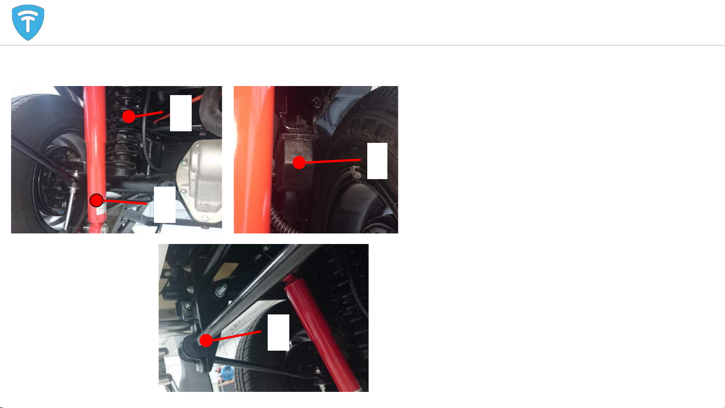
Rear suspension overview
A. Springs
B. Dampers
C. Arms
D. Swaybar
E. Rubber stop
F. Brackets and spacers
Springs and arms connected to the frame
Dampers connected with brackets and spacers spacers
Stabilizing rod also connected with brackets and spacers
5

●Known issues with the rear axle
○Noise when pushing tuk (low tone) indicative of a
broken differential
○Motor turning, but vehicle does not move
■Either differential or drive shafts are broken
○Contaminated oil will lead to differential failure
(make sure there are no loose metal parts in the oil)
○When replacing the differential, it is advised to also
replace the drive shafts. Old and new components
may not be mix&match
○Oil leaks can be caused by bad seals:
■Drive shaft seals
■Differential gasket
■Differential side seals
■Differential motor seal
Rear axle and differential: Maintenance 6
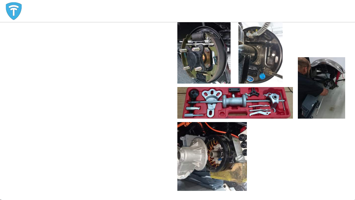
Differential removal and installation part 1
1. Disassemble drive shafts
a. Remove wheels and brake drums to reveal drive shaft.
b. Unbolt the 4 M8 bolts from the back of the drum brake
anchor plate.
c. Use an axle puller set to remove the axle
2. Remove the motor
a. Perform service power disconnect and disconnect the
main battery B- from the motor controller (see safety
instruction section)
b. Open the motor cable enclosure and disconnect all
cables and connectors. Remove the motor cable
enclosure.
c. Unbolt 6 M6 hex bolts from the motor.
d. Support the motor with a garage jack and slide it from
the drive axle (to the right).
e. Installation is the reverse procedure
f. Apply grease on the spline before installing the motor
g. Torque values:
i. Motor flange M6: 14Nm
ii. Motor cable terminal: 12Nm
Rear axle and differential maintenance 7
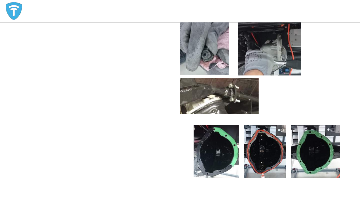
Differential removal and installation part 2
3. Remove the draining plug (underside differential bell housing)
and drain all differential oil, check the inside of the plug for
metal debris (there is a magnet here). Lots of debris indicates
excessive gear wear.
4. Unbolt all differential bolts and remove the differential. (Pre
2017 vehicles have axle structure that needs to be removed as
well. If this structure is welded in place it needs to be cut away
and reinstalled using a retrofit flange kit)
Installation:
1. Thoroughly clean the inside of the axle and all parts to remove
all debris and dirt.
2. Clean the contact surface of differential and axle and put
silicone gasket sealer paste on the flange and install the green
gasket.
3. Fit new differential, use lock bonding material on the bolts and
tighten the bolts with 14Nm. (TTF recommends to install new
drive shafts whenever installing a new differential)
4. Fill the differential with 80ml Tranself B 80W90.
5. Reassemble all other parts.
Rear axle and differential maintenance 8

●The Tuk Tuk has several body parts that can be
replaced in case of damage.
●Please check type of e-tuk before ordering spare
parts, older Tuk Tuks have different body parts
than the Limo GT.
Body replacement 9
Old Tuk Tuk has a small step-in and a
continuous body around the passenger
section
New Limo GT Tuk Tuk has a large step-in
and smaller body panels surrounding the
passengers

10
Electrical, hardware

Safe working on the electric drive train - work procedure 11
Work on the motor, battery or controller After an accident or when in
doubt of hazard
Call Tuk Tuk
Factory first!
Dashboard
1. Remove rear bench
2. Open controller box
3. Remove blue relay
Back
1. Put the vehicle in neutral
2. Use the parking brake
3. Turn the vehicle off
4. Mark the spot
Dashboard
Battery
type?
Start procedure 1. Check for visible danger
2. Turn vehicle back on
After procedure
Lithium
Lead acid
1. Unscrew B- terminal
2. Isolate B-terminal
Back
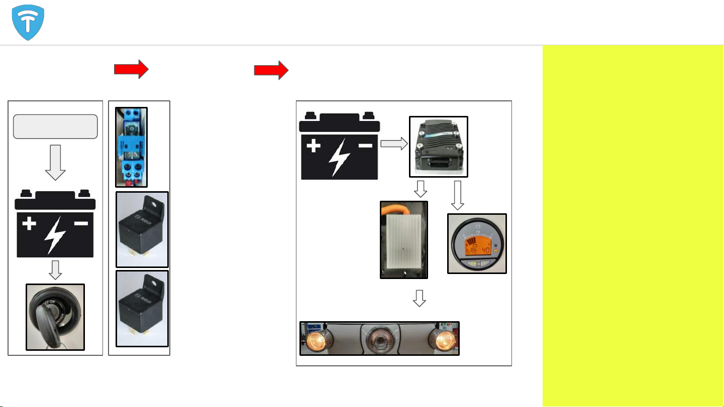
Electric system: Starting sequence 12
12 V
DC-DC
15
Controller
DC-DC
Converter
START
Electric system: Starting sequence
If the starting procedure works,
the controller should turn on. The
yellow LED on the controller
flashes. If it does not work, check
all steps in the sequence.
The controller uses several input
signals to work as desired. If the
controller turns on but does not
respond as expected, check the
input signals with the 1313
handheld controller:
1. KSI
2. DNR switch
3. Throttle
4. Kill switch
5. Brake switch
6. Charger inhibit
7. BDI
8. Motor sensors
9. Speedmode
10. CANbus
1 2 3
12V battery powers
the KEY SWITCH
KEY SWITCH
turns on 3 relays All systems turn on
BDI
Controller key relay (blue)
1. 72V battery
(fused) with
controller key
wire
2. Key wire turns on
controller/DC-DC/
BDI
3. Lithium battery
key input (if
applicable)
In fusebox: 2 relays for
12V system
1. DC-DC -> 15
2. 12V -> 15
72 V

DC/DC relay
connects DC/DC
converter with 15
track.
12V battery will be
charged when
both relays are
engaged
15 switched relay
connects 15 track
with 12V battery.
Useful information and
recommendations:
Possible complaints:
●Tuk does not turn on
●Lights are not bright
enough
●Several devices do not
work
How to identify power supply
issues:
●Measure 12V battery
voltage. Should be higher
than 12V when vehicle is
off, should be over 13.2V
when vehicle is on
●Check function relays; feel
them ‘click’ or measure in
and output
●Check fuses in fuse box
and inline fuses of key
switch and DC/DC
converter
Electric system: Fuse box
*All electric diagrams are available in this course*
13

CONTROLLER
35P
MAIN
CONTACTOR
DC/DC
CONVERTER
KEY FUSE
KEY RELAY
MAIN FUSE
OPTO ADAPTER
DCDC FUSE
COMPONENTS:
●MOTOR CONTROL
○CONTROLLER
○35P
○MAIN CONTACTOR
○MAIN FUSE
●POWER ON
○KEY FUSE
○Controller KEY
RELAY
○DC/DC FUSE
●POWER
○DC/DC converter
○Charger connection
●COMMUNICATION
○CANbus connector
○CAN Optoadapter
○Serial connector
Electric system: Controller board components 14

12V battery empty.
●If the 12V battery is not charged, the
vehicle will not start. A starter battery
should be connected to power on all
systems.
●When systems are restarted the cause of
the problem should be determined.
Check if voltage of battery is >13.1V
●Probable causes:
○Too low voltage from DC/DC
converter. Implement DC/DC
rework solution (thicker cable)
○DC/DC fuse broken. Install 30A
fuse
○DC/DC relay broken
○Blue key relay broken
○No power from main battery
○DC/DC converter broken
Blown fuses
●A blown fuse will stop energy flow
to a device. A blown fuse usually
indicates a issue somewhere in the
fused circuit. Whenever a fuse is
blown, the reason for failure should
be verified. Possible causes:
○Wrong fuse value. The right values
can be found in the wiring
diagrams
○Short circuit in a wire, caused by
wire break or cut.
○Too much load on a circuit. Any
auxilary devices should not be
directly connected to one of the
existing circuits. The aux plugs
(for charging phone or navigation
system) can only deliver 120W.
15
Common issues
Isolation error
●The lithium battery measures
the isolation between B- and
the chassis. If measured
values are below 30.000Ohm,
it gives an error and shuts
down.
●Common areas which can
cause isolation errors:
○Canbus optoadapter
○Battery Key or canbus cable
○Speedometer optoadapter
○Wrong contact on B- or
chassis
○Grounding error. Make sure
controller box is mounted
firmly to chassis.
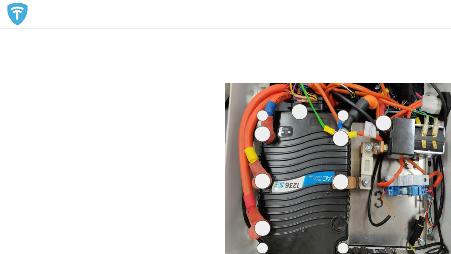
Electric system: Controller replacement procedure 1
Removal
1. Turn vehicle off
2. Disconnect 35P connector
3. Disconnect B- and isolate B- battery cable with
tape.
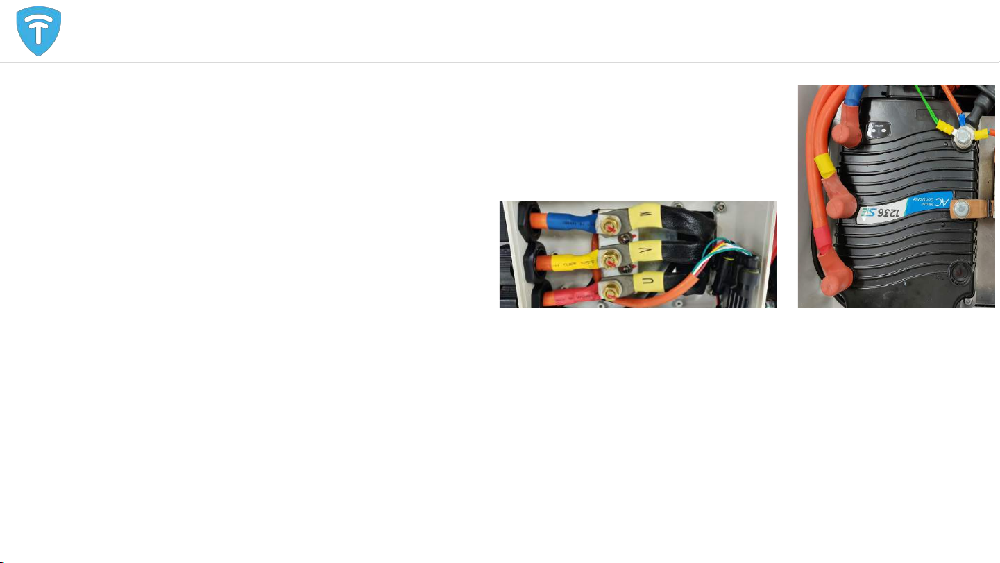
4. Disconnect all motor cables
5. Disconnect B+ bus bar
6. Unbolt controller 4xm6 hex bolts
7. Remove controller
Placement
●Please follow the previous steps in reverse
●Use torque wrench (14 Nm) for steps 3,4 & 5.
16
2
3
3
4
4
4
6
5
6
66
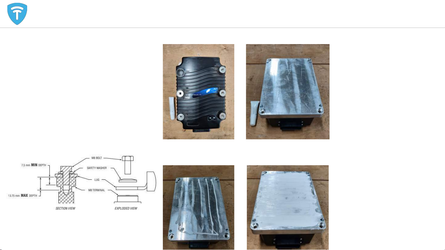
Electric system: Controller replacement procedure 2
Installation
1. Clean surfaces controller and
aluminium plate
2. Apply heat conductive paste
3. Position controller on alu plate
and bolt down.
4. Connect all cables. Fasten bolts
with 14Nm
5. Connect 35pin connector
Place controller and thermal paste on clean desk. Flip controller and clean surface.
Apply thermal paste in thin lines. Spread with back of tube, evenly over the whole
surface.
17
Source: Curtis
Electric system: Controller thermal issues
Background
The controller’s safe operating
temperature is -25°C to +85°C. During
driving (mainly accelerating and motor
braking) the controller heats up.
Whenever driving in warm climates there
is a chance that the controller temperature
will rise above +85°C. When it does, the
controller will give an error and max speed
will be reduced.
It is best to stop driving and let the
controller cool down.
If the C_hot error occurs regularly, there
might be another problem:
1. Dirt
The controller and heat sink need to be cleaned of dirt.
2. Terminals
These terminals need to be secured properly.
3. Heat sink alignment
- Underneath the heat sink are screws that can be tightened.
- The bolts, securing the controller, can be tightened.
- The cooling paste can be removed and applied (see slide: ‘controller - hardware
replacement procedure’).
4. Wheels
Lift the vehicle to check if the wheels can turn freely (see slides regarding rear
suspension, axle and differential).
18

1. Connect vehicle to PC using CURTIS 1314 cable.
2. Select software version .exe file:
1236, 1238: Folder 123x
Lead Acid_tuktuk135_123x_20170623
1234SE, 1236SE, 1236E: Folder 123xse
Lithium_tuktuk150_123XSE_20180110
Lead Acid_tuktuk141_123XSE_20170623
3. Run .exe file with latest software from PC
4. Select correct COM port (PC specific)
5. FLASH
6. Update user and OS defaults from .exe software
19
Controller - software - installation procedure 1

8. Perform a test drive and check all
functionality using the monitor menu
of the handheld programmer
a. Speeds
b. Driving direction
c. Acceleration and
deceleration
behaviour
d. Throttle response
e. Charger inhibit
f. Foot brake
g. Kill switch
h. Max battery current
(for lithium battery)
7. Open software pack. Verify battery and controller
type.
1236, 1238: Folder 123x
Old motor: 1236_OS12_ADC_Lead Acid_20170623
New motor: 1236_OS12_KDS_Lead
Acid_20170623
8. 1234SE, 1236SE, 1236E: Folder 123xse
1236SE_OS26_KDS_Lithium_20171204
1236SE_OS26_KDS_Lead Acid_20171026
9. Select ‘connect’ in PC programming station
10. Send software to connected controller. Make sure
advanced cloning is selected.
11. Follow on screen instruction: turn vehicle off and
wait 5 seconds before turning it on again.
12. Change parameters manually (values are located
on top of controller box).
a. Can Interface/Baud Rate
b. Motor Control Tuning/IM Motor
Characterization Tests/SlipGain
20
Controller - software - installation procedure 2


