TTI tg2000 User manual

THURLBY THANDAR INSTRUMENTS
20MHz DDS FUNCTION GENERATOR
TG2000
INSTRUCTION MANUAL

Table of Contents
Introduction 2
Specifications 3
Safety 6
EMC 8
Installation 9
Connections 10
Front Panel Connections 10
Rear Panel Connections 11
General 12
Initial Operation 12
Standard Waveform Operation 15
Setting Generator Parameters 15
AUX Output 18
Warnings and Error Messages 19
Sweep Operation 20
General 20
Setting Sweep Parameters 20
Gated Mode 25
Tone Mode 26
FSK 27
Modulation 28
System Operations from the Utility Menu 29
Calibration 31
Equipment Required 31
Calibration Procedure 31
Calibration Routine 32
Remote Calibration 33
Remote Operation 34
USB Interface 38
Remote Commands 39
Maintenance 42
Appendix 1. Warning and Error Messages 43
Appendix 2. Factory System Defaults 44
1

Introduction
This Programmable Function Generator uses direct digital synthesis to provide high performance
and extensive facilities at a breakthrough price. It can generate a variety of waveforms between
1mHz and 20MHz with a resolution of 6 digits and an accuracy better than 10ppm.
Direct digital synthesis for accuracy & stability
Direct digital synthesis (DDS) is a technique for generating waveforms digitally using a phase
accumulator, a look-up table and a DAC. The accuracy and stability of the resulting waveforms is
related to that of the crystal master clock.
The DDS generator offers not only exceptional accuracy and stability but also high spectral purity,
low phase noise and excellent frequency agility.
A wide range of waveforms
High quality sine, square and pulse waveforms can be generated over the full frequency range of
1mHz to 20MHz.
Triangle waveforms can also be generated but with limitations as to the maximum useable
frequency.
Variable symmetry/duty-cycle is available for squarewave and pulse waveforms.
Sweep
All waveforms can be swept from 0.2Hz to their maximum frequency in a single sweep at a rate
variable between 50 milliseconds and 999 seconds. The sweep is fully phase continuous.
Sweep can be linear or logarithmic, single or continuous. Single sweeps can be triggered from
the front panel, the trigger input, or the digital interfaces. A sweep marker is provided.
AM
External Amplitude Modulation is available for all waveforms.
FSK and Tone modes
Frequency Shift Keying provides phase coherent switching between two selected frequencies; in
Tone mode the output is stepped asynchronously through a user-defined list of up to 16
frequencies. In both modes the switching source can be the internal trigger generator, front panel,
an external signal or a remote command.
Easy and convenient to use
All of the main generator parameters are clearly displayed together on a backlit LCD with 4 rows
of 20 characters. Sub menus are used to set the parameters for each function.
All parameters can be entered directly from the numeric keypad. Alternatively most parameters
can be incremented or decremented using the rotary encoder.
This system combines quick and easy numeric data entry with quasi-analogue adjustment when
required.
Fully programmable via USB and Addressable RS-232
The generator has both USB and RS-232 interfaces which can be used for remote control of all of
the instrument functions.
As well as operating in conventional single instrument mode the RS-232 serial interface can also
be used in addressable mode whereby up to 32 instruments can be linked to a single PC serial
port.
2

Specifications
Specifications apply at 18°- 28°C after one hour warm-up, at maximum output into 50Ω.
WAVEFORMS
Standard waveforms of sine, square, triangle, DC, positive pulse and negative pulse.
Sine
Range: 1mHz to 20MHz
Resolution: 1mHz or 6 digits
Accuracy: 10 ppm for 1 year; ± 1mHz below 0.2Hz
Temperature Stability: Typically <1 ppm/ºC outside 18° to 28°C
Output Level: 2.5mV to 10Vp−p into 50Ω
Harmonic Distortion: <0.3% THD to 20kHz (typically 0.1%)
<–45dBc to 300kHz
<−35dBc to 20MHz (typically <−40dBc)
Non−harmonic Spurii: <–55dBc to 1MHz, <–55dBc + 6dB/octave 1MHz to 20MHz
Square
Range: 1mHz to 20MHz
Resolution: 1mHz or 6 digits
Symmetry Control: 20% to 80% (1% resolution) 1mHz to 20MHz
Accuracy: 10 ppm for 1 year; ± 1mHz below 0.2Hz
Output Level: 2.5mV to 10Vp−p into 50Ω
Rise and Fall Times: <22ns
Aberrations: <5% + 2mV
Triangle
Range: 1mHz to 1 MHz
Resolution: 1mHz or 6 digits
Accuracy: 10 ppm for 1 year; ± 1mHz below 0.2Hz
Output Level: 2.5mV to 10Vp−p into 50Ω
Linearity Error: <0.5% to 100 kHz
Positive and Negative Pulses
Range: 1mHz to 20MHz
Resolution: 1mHz or 6 digits
Symmetry Control: 20% to 80% (1% resolution) 1mHz to 10MHz
Accuracy: 10 ppm for 1 year; ± 1mHz below 0.2Hz
Output Level: 1.25mV to 5Vp-p into 50Ω positive or negative only pulses, with respect
to the DC Offset baseline.
Rise and Fall Times: <22ns
Aberrations: <5% + 2mV
OPERATING MODES
Continuous
Continuous cycles of the selected waveform are output at the programmed frequency.
3

Gated
Non-phase coherent gating - output carrier wave is on while Gate signal is high and off while low.
Carrier frequency: From 1mHz to 20MHz.
Carrier waveforms: All
Trigger rep. rate: DC to 100 kHz external; to 5kHz using internal trigger generator.
Gate signal source: Manual (front panel MAN TRIG key), external signal (TRIG/GATE IN),
internal gate generator or remote interface.
Sweep
Carrier Waveforms: All
Sweep Mode: Linear or logarithmic, single or continuous.
Sweep Width: From 0.2Hz to 20MHz in one range. Phase continuous. Independent
setting of the start and stop frequency.
Sweep Time: 50ms to 999s (3 digit resolution).
Marker: Available from AUX output. Variable during sweep.
Sweep Trigger Source: The sweep may be free run or triggered from any of the following sources:
Manual (front panel MAN TRIG key), external from TRIG/GATE IN or from
remote interface.
External Amplitude Modulation
Carrier Frequency: From 1mHz to 20MHz.
Carrier Waveforms: All
Modulation Source: VCA IN socket
Frequency Shift Keying (FSK)
Phase coherent switching between two selected frequencies at a rate defined by the switching
signal source.
Carrier frequency: From 1Hz to 20MHz.
Carrier waveforms: All
Switch repetition rate: DC to 5kHz (internal trigger) or DC to 1MHz (external trigger).
Switching signal source: Manual (front panel MAN TRIG key), internal trigger generator, external
signal (TRIG/GATE IN) or remote interface.
Tone
The tone is output while the trigger signal is high and stopped while the trigger signal is low. The
next tone is output when the trigger signal is high again.
Carrier Waveforms: All
Frequency List: Up to 16 frequencies from 1Hz to 20MHz
Switching Source: Manual (front panel MAN TRIG key), internal trigger generator, external
signal (TRIG/GATE IN) or remote interface.
Min Switching Time: 1ms per tone
OUTPUTS
Main Output
Output Impedance: 50Ωor 600Ω
Amplitude: 5mV to 20V pk-pk open circuit, (2.5mV to 10V pk-pk into 50Ω/600Ω).
Output can be specified as HiZ (open circuit value) or V (voltage into
characteristic impedance) in pk-pk, r.m.s. or dBm.
Amplitude Accuracy: ±3% ±1mV at 1kHz into 50Ω/600Ω.
Amplitude Flatness: ±0.2dB to 500kHz; ±2dB to 20MHz.
4

DC Offset Range: ±10V. DC offset plus signal peak limited to ±10V from 50Ω/600Ω.
DC Offset Accuracy: typically ±3% ±10mV, unattenuated.
Resolution: 3 digits for both Amplitude and DC Offset.
Pulse Aberrations: <5% + 2mV.
Aux Out
Multifunction output user definable or automatically selected to be any of the following:
Waveform Sync: A square wave at the main waveform frequency. Symmetry is 50% for
sine and triangle waves at MAIN OUT; for square waves and pulses
symmetry is the same as that of the waveform at MAIN OUT.
Trigger: Outputs a replica of the current trigger signal.
Sweep Sync: Outputs a trigger signal at the start of sweep to synchronize an
oscilloscope. Can additionally output a sweep marker.
Output Signal Level: Output impedance 50Ω nominal. Logic levels of <0.8V & >3V, except
for Sweep Sync. Sweep Sync is a 3-level waveform: low at start of
sweep, high for the duration of the last frequency step at end of sweep,
with a narrow 1V pulse at the marker point.
INPUTS
Ext Trig /Gate
Frequency Range: DC - 1MHz for FSK; DC – 100kHz for Gate; DC – 2.5kHz for Tone and
Sweep.
Signal Range: Threshold nominally TTL level; maximum input ±10V.
Minimum Pulse Width: 100ns for Gate and FSK modes; 0.2ms for Sweep and Tone modes.
Input Impedance: 10kΩ
VCA In
Frequency Range: DC - 100kHz.
Signal Range: 2.5V for 100% level change at maximum output.
Input Impedance: typically 6kΩ.
INTERFACES
RS-232: Variable Baud rate, 19200 Baud maximum. 9-pin D-connector.
As well as operating in a conventional RS-232 mode the interface can
be operated in addressable mode whereby up to 32 instruments can be
addressed from one RS-232 port.
USB: Standard USB hardware connection.
GENERAL
Display: 20 character x 4 row alphanumeric LCD.
Data Entry: Keyboard selection of mode, waveform etc.; value entry direct by
numeric keys or by rotary control.
Stored Settings: Up to 9 complete instrument set-ups may be stored and recalled from
non-volatile memory.
Size: 260(W) x 88(H) x 235(D)
Weight: 2kg. (4.5lb.)
Power: 110-120V AC or 220V-240V AC ±10%, 50/60Hz,
adjustable internally; 35VA max. Installation Category II.
Operating Range: +5°C to 40°C, 20-80% RH.
Storage Range: -20°C to + 60°C.
Environmental: Indoor use at altitudes up to 2000m, Pollution Degree 2.
Safety & EMC: Complies with EN61010-1 & EN61326.
5

Safety
This generator is a Safety Class I instrument according to IEC classification and has been
designed to meet the requirements of EN61010−1 (Safety Requirements for Electrical Equipment
for Measurement, Control and Laboratory Use). It is an Installation Category II instrument
intended for operation from a normal single phase supply.
This instrument has been tested in accordance with EN61010−1 and has been supplied in a safe
condition. This instruction manual contains some information and warnings which have to be
followed by the user to ensure safe operation and to retain the instrument in a safe condition.
This instrument has been designed for indoor use in a Pollution Degree 2 environment in the
temperature range 5°C to 40°C, 20% −80% RH (non−condensing). It may occasionally be
subjected to temperatures between +5° and −10°C without degradation of its safety. Do not
operate while condensation is present.
Use of this instrument in a manner not specified by these instructions may impair the safety
protection provided. Do not operate the instrument outside its rated supply voltages or
environmental range.
WARNING! THIS INSTRUMENT MUST BE EARTHED
Any interruption of the mains earth conductor inside or outside the instrument will make the
instrument dangerous. Intentional interruption is prohibited. The protective action must not be
negated by the use of an extension cord without a protective conductor.
When the instrument is connected to its supply, terminals may be live and opening the covers or
removal of parts (except those to which access can be gained by hand) is likely to expose live
parts. The apparatus shall be disconnected from all voltage sources before it is opened for any
adjustment, replacement, maintenance or repair.
Any adjustment, maintenance and repair of the opened instrument under voltage shall be avoided
as far as possible and, if inevitable, shall be carried out only by a skilled person who is aware of
the hazard involved.
If the instrument is clearly defective, has been subject to mechanical damage, excessive moisture
or chemical corrosion the safety protection may be impaired and the apparatus should be
withdrawn from use and returned for checking and repair.
Make sure that only fuses with the required rated current and of the specified type are used for
replacement. The use of makeshift fuses and the short−circuiting of fuse holders is prohibited.
Do not wet the instrument when cleaning it and in particular use only a soft dry cloth to clean the
LCD window.
The following symbols are used on the instrument and in this manual:−
Caution −refer to the accompanying documentation, incorrect operation may
damage the instrument.
terminal connected to chassis ground.
mains supply OFF.
l mains supply ON.
alternating current.
6

EC Declaration of Conformity
We Thurlby Thandar Instruments Ltd
Glebe Road
Huntingdon
Cambridgeshire PE29 7DR
England
declare that the
TG2000 20MHz DDS Function Generator
meets the intent of the EMC Directive 2004/108/EC and the Low Voltage Directive 2006/95/EC.
Compliance was demonstrated by conformance to the following specifications which have been
listed in the Official Journal of the European Communities.
EMC
Emissions: a) EN61326-1 (2006) Radiated, Class B
b) EN61326-1 (2006) Conducted, Class B
c) EN61326-1 (2006) Harmonics, referring to EN61000-3-2 (2006)
Immunity: EN61326-1 (2006) Immunity Table 1, referring to:
a) EN61000-4-2 (1995) Electrostatic Discharge
b) EN61000-4-3 (2006) Electromagnetic Field
c) EN61000-4-11 (2004) Voltage Interrupt
d) EN61000-4-4 (2004) Fast Transient
e) EN61000-4-5 (2006) Surge
f) EN61000-4-6 (2007) Conducted RF
Performance levels achieved are detailed in the user manual.
Safety
EN61010-1 Installation Category II, Pollution Degree 2.
CHRIS WILDING
TECHNICAL DIRECTOR
2May 2009
7

EMC
This instrument has been designed to meet the requirements of the EMC Directive 2004/108/EC.
Compliance was demonstrated by meeting the test limits of the following standards:
Emissions
EN61326-1 (2006) EMC product standard for Electrical Equipment for Measurement, Control and
Laboratory Use. Test limits used were:
a) Radiated: Class B
b) Conducted: Class B
c) Harmonics: EN61000-3-2 (2006) Class A; the instrument is Class Aby product category.
Immunity
EN61326-1 (2006) EMC product standard for Electrical Equipment for Measurement, Control and
Laboratory Use.
Test methods, limits and performance achieved are shown below (requirement shown in
brackets):
a) EN61000-4-2 (1995) Electrostatic Discharge : 4kV air, 4kV contact, Performance A (B).
b) EN61000-4-3 (2006) Electromagnetic Field:
3V/m, 80% AM at 1kHz, 80MHz – 1GHz: Performance A (A) and 1.4GHz to 2GHz:
Performance A (A); 1V/m, 2.0GHz to 2.7GHz: Performance A (A).
c) EN61000-4-11 (2004) Voltage Interrupt: ½ cycle and 1 cycle, 0%: Performance A (B);
25 cycles, 70%: Performance A (C); 250 cycles, 0%: Performance B (C).
d) EN61000-4-4 (2004) Fast Transient, 1kV peak (AC line), 0·5kV peak (signal connections),
Performance A (B).
e) EN61000-4-5 (2006) Surge, 0·5kV (line to line), 1kV (line to ground), Performance A (B).
f) EN61000-4-6 (2007) Conducted RF, 3V, 80% AM at 1kHz (AC line only; signal
connections <3m, therefore not tested), Performance A (A).
According to EN61326 the definitions of performance criteria are:
Performance criterion A: ‘During test normal performance within the specification limits.’
Performance criterion B: ‘During test, temporary degradation, or loss of function or
performance which is self-recovering’.
Performance criterion C: ‘During test, temporary degradation, or loss of function or
performance which requires operator intervention or system reset occurs.’
Cautions
To ensure continued compliance with the EMC directive the following precautions should be
observed:
a) connect the generator to other equipment using only high quality, double−screened cables.
b) after opening the case for any reason ensure that all signal and ground connections are
remade correctly before replacing the cover. Always ensure all case screws are correctly
refitted and tightened.
c) In the event of part replacement becoming necessary, only use components of an identical
type, see the Service Manual.
8

Installation
Mains Operating Voltage
Check that the instrument operating voltage marked on the rear panel is suitable for the local
supply. Should it be necessary to change the operating voltage, proceed as follows:
1) Disconnect the instrument from all voltage sources.
2) Unclip the front bezel by gently pulling the centre of each long edge up and forward.
The case halves are held together by 4 plastic push-rivets. Use the blade of a small
screwdriver in the slot beside each rivet to first ease out the rivet head and then fully remove
the rivet body. Separate the case halves. Visit www.tti-test.com for further details.
3) Remove the screws securing the pcb to the case lower and lift out the pcb with front and rear
panels attached; lift one side of the pcb at a time, with the case pcb clips on that side pulled
clear of the pcb edge.
4) Change the voltage settings by changing the soldered links beside the transformer:
For 230V operation fit link LK2 only
For 115V operation fit links LK1 and LK3 only
5) Reassemble in the reverse order.
6) To comply with safety standard requirements the operating voltage marked on the rear panel
must be changed to clearly show the new voltage setting.
7) Change the fuse to suit the new operating voltage, see below.
Fuse
Ensure that the correct mains fuse is fitted for the set operating voltage. The correct mains fuse
types are:
for 230V operation: 250 mA (T) 250V HRC
for 100V or 115V operation: 500 mA (T) 250V HRC
The use of makeshift fuses or the short−circuiting of the fuse holder is prohibited.
Mains Lead
Connect the instrument to the AC supply using the mains lead provided. Should a mains plug be
required for a different mains outlet socket, a suitably rated and approved mains lead set should
be used which is fitted with the required wall plug and an IEC60320 C13 connector for the
instrument end. To determine the minimum current rating of the lead-set for the intended AC
supply, refer to the power rating information on the equipment or in the Specification.
WARNING! THIS INSTRUMENT MUST BE EARTHED.
Any interruption of the mains earth conductor inside or outside the instrument will make the
instrument dangerous. Intentional interruption is prohibited.
9
Connections
Front Panel Connections
MAIN OUT
This is the output from the main generator; output source impedance can be set to 50Ω or 600Ω.
It will provide up to 20V peak−to−peak e.m.f. which will yield 10V peak-to-peak into a matched
load. It can tolerate a short circuit for 60 seconds.
Do not apply external voltages to these outputs.
AUX OUT
This is a TTL/CMOS level output which may be set to any of the following signals from the
AUX OUT screen.
waveform sync A sync signal phase coincident with the MAIN OUT waveform. For sine
and triangle waves the sync waveform rising edge is at the 0º phase
point of MAIN OUT and the falling edge is at the 180º phase point. For
square waves and pulses both phase and symmetry are coincident with
MAIN OUT.
Trigger Provides a replica version of the actual trigger signal; internal, external,
manual and remote all produce a trigger sync.
Sweep sync Goes low at the start of sweep and high at the last frequency step of
the sweep. In addition, a 1/4-amplitude marker pulse can be output at
a specified marker frequency.
AUX OUT logic levels are nominally 0V and 5V from typically 50Ω. AUX OUT will withstand a
short circuit.
Do not apply external voltage to this output.
TRIG/GATE IN
This is the external input for Trigger, Gate and Sweep operations.
Do not apply external voltages exceeding ±10V.
VCA IN
This is the input socket for external amplitude modulation.
Do not apply external voltages exceeding ±10V.
10

Rear Panel Connections
RS-232
9−pin D−connector compatible with addressable RS-232 use. The pin connections are shown
below:
Pin Name Description
1 −No internal Connection
2 TXD Transmitted data from instrument
3 RXD Received data to instrument
4 −No internal connection
5 GND Signal ground
6 −No internal connection
7 RXD2 Secondary received data
8 TXD2 Secondary transmitted data
9 GND Signal ground
Pin 2, 3 and 5 may be used as a conventional RS-232 interface with XON/XOFF handshaking.
Pins 7, 8 and 9 are additionally used when the instrument is used in addressable RS-232 mode.
Signal grounds are connected to instrument ground. The RS-232 address is set from the
remote menu on the UTILITY screen, see System Operations section.
USB
The USB port accepts a standard USB cable. The Windows plug-and-play functions should
automatically recognise that the instrument has been connected.
11

General
Initial Operation
This section is a general introduction to the organisation of the instrument and is intended to be
read before using the generator for the first time. Detailed operation is covered in later sections
starting with Standard Waveform Operation.
In this manual front panel keys and sockets are shown in capitals, e.g. STATUS, AUX OUT; all
soft−key labels, entry fields and messages displayed on the LCD are shown in a different
type−font, e.g. WAVEFORM, sine.
DDS Principles
In this instrument waveforms are generated by Direct Digital Synthesis (DDS). A phase
accumulator is incremented at a rate proportional to the required output frequency. The most
significant 12 bits of the accumulator are used to address a look-up table ROM that converts the
phase information into sinewave amplitude data; this data is then passed to a 10-bit Digital-to-
Analogue Converter (DAC) which produces the output waveform. For triangle waves the ROM
look-up table is by-passed and the phase accumulator output is passed directly to the DAC.
At low frequencies all 4096 points in the output wave are stepped through, but as the frequency
increases points are progressively missed out. Sinewaves and triangles are subsequently filtered
to smooth the steps in the DAC output; this technique ensures good sinewave purity up to the
maximum frequency of the generator but the practical limit to which excellent triangle linearity is
maintained is only about 100kHz. Squarewaves and pulses are derived from the sinewave using
a variable threshold comparator; this permits symmetry control of these waveforms across the
whole instrument frequency range.
The major advantages of DDS over conventional analogue generation are:
• Frequency accuracy and stability is that of the crystal oscillator.
• Frequencies can be set with high resolution from mHz to MHz.
• Low phase noise and distortion.
• Very wide frequency sweeps are possible.
• Fast phase continuous frequency switching.
• In addition, being a digital technique, it is easier to make every parameter programmable from
the keyboard, or remotely via the USB or RS-232 interfaces.
Switching On
Switch on the generator using the ON/OFF switch on the rear panel. To fully disconnect from the
AC supply unplug the mains cord from the back of the instrument or switch off at the AC supply
outlet; make sure that the means of disconnection is readily accessible. Disconnect from the AC
supply when not in use.
At power up the generator displays the installed software revision and conducts a self-test.
Power-on self-test takes a few seconds, after which the status screen is displayed, showing the
generator parameters set to their default values, with the MAIN OUT output set off. Refer to the
System Operations section for how to change the power up settings to either those at power
down or to any one of the stored settings. Recall the status screen at any time with the STATUS
key; a second press returns the display to the previous screen.
Change the basic generator parameters as described in the Standard Waveform Operation
section and switch the output on with the ON key; the lamp above the key will light to show that
output is on.
12

Display Contrast
All parameter settings are displayed on the 20 character x 4 row backlit liquid crystal display
(LCD). The contrast may vary a little with changes of ambient temperature or viewing angle but
can be optimised for a particular environment by using the front panel contrast control. Insert a
small screwdriver or trimmer tool through the adjustment aperture marked LCD and rotate the
control for optimum contrast.
Keyboard
Pressing the MENU key calls the top-level menu from which all functions can be accessed.
Selections are made from this menu using the display soft-keys and numeric values are then
changed using the numeric keys or rotary control, see the Principles of Editing section.
The keys are as follows:
• MENU calls the top-level menu screen from which the main functions can be directly
selected. These are WAVEFORM, FREQUENCY, AMPLITUDE, DC OFFSET, SYMMETRY,
MODE, UTILITY and AUX OUT. Pressing the associated soft-key of any of these functions
calls a further screen which permits the parameters of that function to be edited either from
the numeric keypad or by using the rotary control/cursor keys.
• Numeric/Unit keys permit direct entry of a value for the parameter currently selected. Thus,
having selected the FREQUENCY screen (by pressing the FREQUENCY soft-key on the
MENU screen), a new frequency of 100kHz, for example, is set by pressing 1, 0, 0, kHz.
CE (Clear Entry) undoes a numeric entry digit by digit. ESCAPE returns a setting being
edited to its last value.
• Eight soft-keys around the display are used to directly set or select parameters from the
currently displayed menu; their operation is described in more detail in the next section.
• The STATUS key always returns the display to the default start-up screen which gives an
overview of the generator’s status. Pressing STATUS again returns the display to the
previous screen.
Further explanations will be found in the detailed descriptions of the generator’s operation in the
sections that follow.
Status Display
After the messages at switch-on, or at any time the STATUS key is pressed, the Status display is
shown. With the generator set to the factory defaults (Appendix 2), the display will be:
WAVE:sine
FREQ:10·0000kHz CONT
AMPL:+4·00Vpp
DC:+0·00Vdc (+0·00V)
This display gives an overview of the status of the main generator parameters. If a waveform is
selected for which symmetry can be set (see Specification) the additional field of SYMmetry is
shown to the right of the waveform type, see example below:
WAVE:square SYM:35%
FREQ:10·0000kHz CONT
AMPL:+4·00V
DC:+0·00Vdc (+0·00V)
For convenience, the WAVEFORM, FREQUENCY, AMPLITUDE, DC OFFSET, SYMMETRY and
MODE screens can be directly selected from the Status display, (i.e. without having to first return
to the main MENU) by pressing the appropriate soft-key beside WAVE, FREQ, AMPL, etc.
13
Principles of Editing
Each screen called up by pressing a soft-key on the top level MENU display shows parameter
value(s) and/or a list of choices. Choices are made using the soft−key associated with the screen
item to be selected. Parameter values can be edited by using the ROTARY CONTROL in
combination with the left and right arrowed CURSOR keys, or by direct numeric keyboard entry;
The examples which follow assume factory default settings.
A diamond beside a screen item indicates that it is selectable; hollow diamonds identify
deselected items and filled diamonds denote selected items. For example, press the MODE
soft-key on the main menu to get the screen shown below:
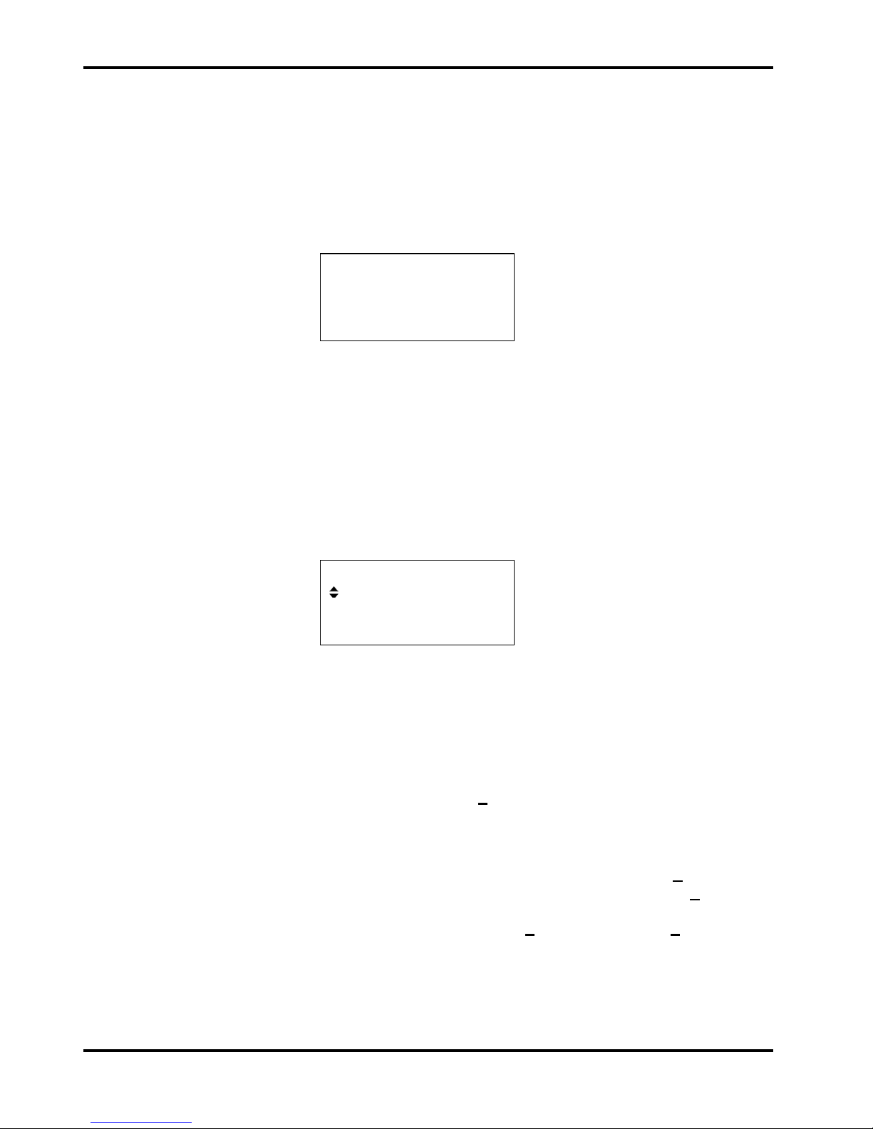
MODE more…◊
♦continuous
◊gated setup…◊
◊sweep setup…◊
The filled diamond indicates that the selected mode is continuous.Gated or sweep
modes are selected by pressing the associated soft−key which will make the diamond beside that
item filled and the diamond beside continuous hollow. This screen also illustrates how an
ellipsis (three dots following the screen text) indicates that a further screen follows when that item
is selected. In the case of the MODE screen illustrated, pressing the setup... soft−key on the
bottom line brings up the SWEEP SETUP menu; note that selecting this item does not change
the continuous mode selection.
Some screen items are marked with a double−headed arrow (a split diamond) when selected to
indicate that the item’s setting can be changed by further presses of the soft−key, by pressing
either cursor key or by using the rotary control. For example, pressing the AUX OUT soft-key on
the main menu brings up the screen shown below.
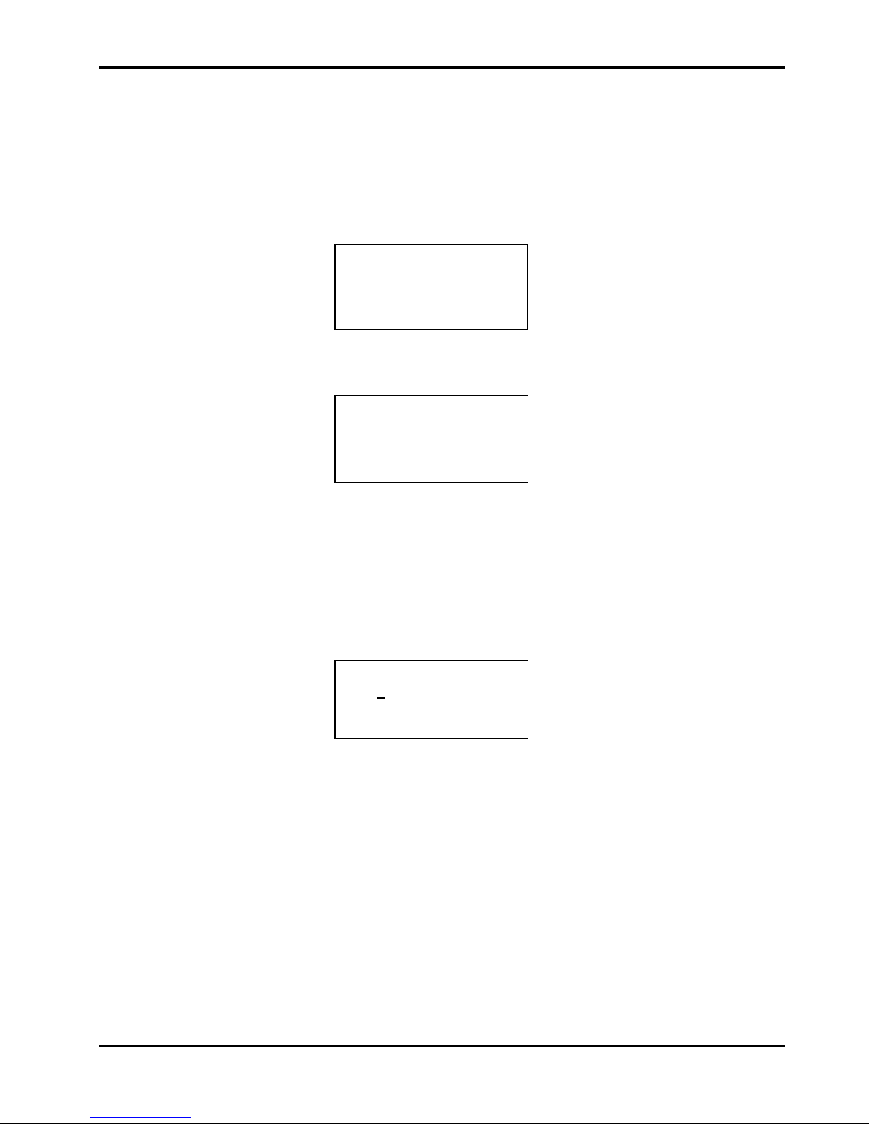
AUX OUT
output: on
◊mode: auto
◊srce: waveform sync
Repeated presses of the output soft-key will toggle the output between on and off.
Similarly when srce (source) is selected, repeated presses of the srce soft-key will step
through all possible selections of the AUX OUT source ( waveform sync, trigger, and
sweep sync ). The rotary control can also be used to step through the selections.
In screens where a parameter with a numeric value is displayed the cursor keys move the edit
cursor (a flashing underline) through the numeric field and the rotary control will increment or
decrement the value; the step size is determined by the position of the edit cursor within the
numeric field. Thus for FREQUENCY set to 1.00000 MHz rotating the control will change
the frequency in 1kHz steps. Turning the control quickly will step numeric values in multiple
increments.
The display will auto-range up or down as the frequency is changed but the increment size and
displayed units are maintained. In the example above (FREQUENCY set to 1.00000 MHz) ,
the lowest frequency that can be set by rotating the control is 1kHz, shown as 0.00100 MHz.
The displayed units can be changed at any time by pressing the appropriate key, e.g. pressing
kHz or Hz will change the display for the above example to 1.00000 kHz or 1000.00 Hz
respectively. To reduce the frequency further using the rotary control it is necessary to move the
cursor to set a smaller increment size.
14
Standard Waveform Operation
When first switched on, and at all subsequent power-ups, unless specified otherwise on the
UTILITY menu, the generator will be set to the factory defaults (Appendix 2), with the MAIN OUT
off. The basic parameters can be changed as described below.
Setting Generator Parameters
Main Menu
The starting point for changing any parameter is the Main Menu, accessed by pressing the MENU
key.
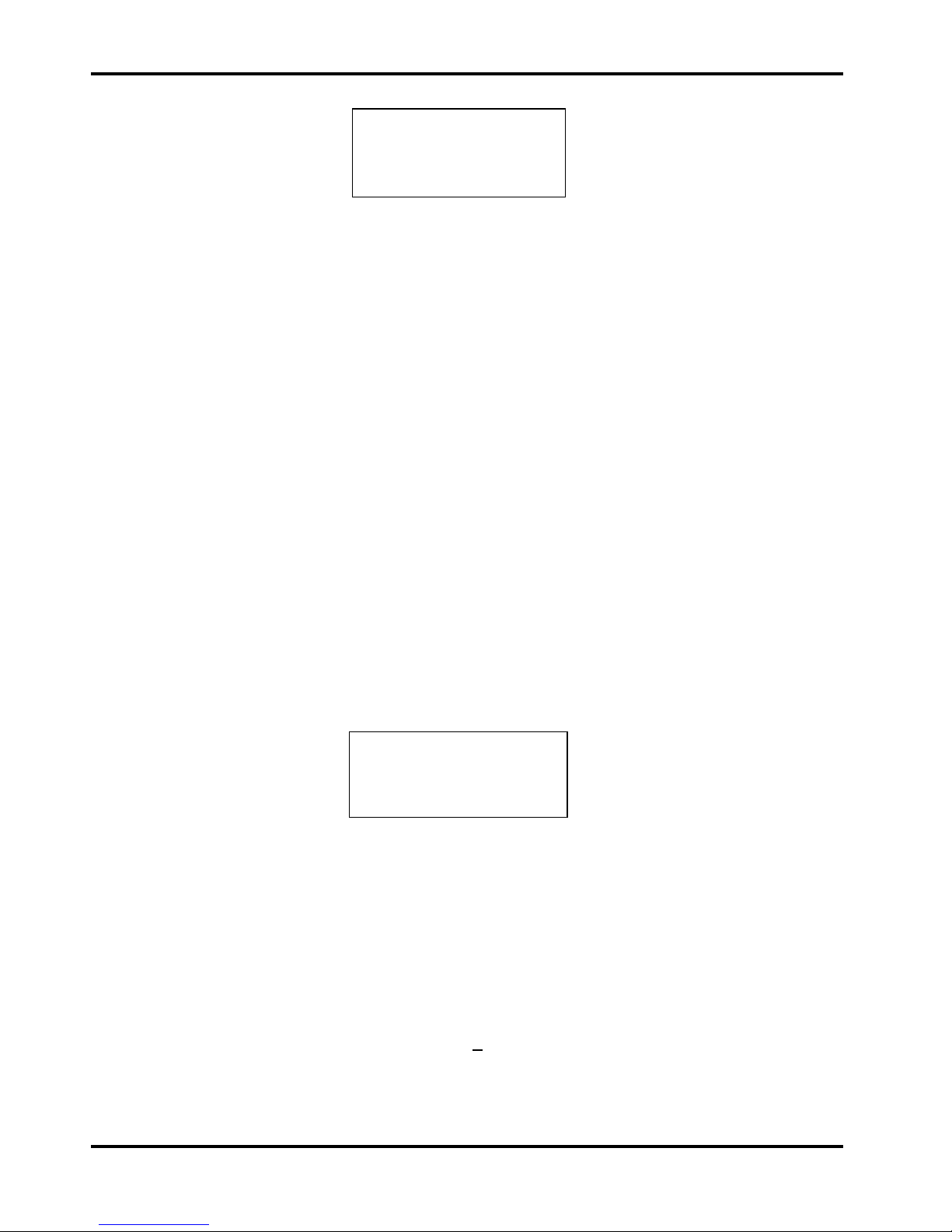
◊WAVEFORM SYMMETRY ◊
◊FREQUENCY MODE ◊
◊AMPLITUDE UTILITY ◊
◊DC OFFSET AUX OUT ◊
The set-up screen for each of the principal parameters is displayed by pressing the appropriate
soft-key on this Main Menu; the parameters can then be changed as described below.
Waveform Selection
WAVEFORM
♦sine +pulse ◊
◊square -pulse ◊
◊triangle dc only ◊
Pressing the WAVE soft-key on the main menu gives the WAVEFORM screen which lists all the
waveforms available. The currently selected waveform (sine with the factory defaults setting) is
indicated by the filled diamond; the selection is changed by pressing the soft−key beside the
required waveform.
Sine square and triangle are bipolar waveforms centred about the baseline level set from the DC
Offset screen; +pulse and –pulse are uni-polar waveforms that are respectively positive and
negative with respect to the baseline. When dc only is selected the output ‘waveform’ is the
baseline DC voltage only, set from the DC Offset screen.
Frequency
FREQUENCY
10·0000 kHz
♦freq period ◊
Pressing the FREQ key gives the FREQUENCY screen. With freq selected as shown above,
the frequency can be entered directly from the keyboard in any convenient units, e.g. 12.34kHz
can be entered directly in kHz but can also be entered as 12340Hz or 0.01234MHz.
With period selected instead of freq the frequency can be set in terms of a period; the
period can be entered directly in any convenient units, e.g. 0.1ms can also be entered as 0.0001s
or 100us. The hardware is actually programmed in terms of frequency and when a period entry is
made the synthesised frequency is the nearest equivalent value that the frequency resolution and
conversion calculation gives. Since the instrument’s frequency resolution is 1mHz there will
generally be no noticeable loss of precision for frequencies above 1kHz (periods <1ms) but the
conversion errors will increase progressively for entries of longer periods; to maintain precision,
low frequencies (<1kHz) should be entered in terms of frequency.
Turning the rotary control will increment or decrement the numeric value in steps determined by
the position of the edit cursor (flashing underline); the cursor is moved with the left and right
arrowed cursor keys.
Note that the upper frequency limits vary for the different waveform types; refer to the
Specifications section for details.
15
Amplitude
AMPLITUDE
+4·00 Vpp Vpp◊
◊srce:50Ω load:hiZ ◊
Pressing the AMPLITUDE soft-key on the main menu gives the AMPLITUDE screen.
The actual source impedance of the generator can be set to either 50Ω(factory default) or 600Ω
with alternate presses of the srce (source) soft-key. In addition, an assumed load of 50Ω,
600Ωor hiZ (open-circuit) can be selected with successive presses of the load soft-key.
When an amplitude setting is made the selected source impedance and expected load
termination are taken into account such that the actual output amplitude is that shown in the
display.
The waveform amplitude can be set in terms of peak-to-peak Volts (Vpp), r.m.s. Volts (Vrms) or
dBm (referenced to a 50Ωor 600Ωterminating load). The most appropriate units can be selected
with successive presses of the units soft-key, which steps through the three options of Vpp,
Vrms and dBm in turn. Note that when dBm is selected a load:hiZ setting is
automatically changed to load:50Ωbecause a termination is always assumed; pressing the
load:50Ωsoft-keys will now only toggle between load:50Ω and load:600Ω
settings.
With the appropriate form of amplitude selected, numeric entries can be made directly from the
keyboard in either mV or Volts, e.g. 250mV can be entered as 250mV or 0.25V. Turning the rotary
control will increment or decrement the numeric value in steps determined by the position of the
edit cursor (flashing underline); the cursor is moved with the left and right arrowed cursor keys.
Alternate presses of the ± key will invert the MAIN OUT output; if DC OFFSET is non−zero, the
signal is inverted about the same offset. The exception to this is if the amplitude is specified in
dBm; since low level signals are specified in −dBm (0dBm = 1mW into 50Ω= 224mVrms) the
−sign is interpreted as part of a new amplitude entry and not as a command to invert the signal.
DC Offset
DC OFFSET
program +0·00 Vdc
(actual +0·00 Vdc)
◊srce:50Ω load:hiZ ◊
Pressing the OFFSET key gives the DC OFFSET screen. The offset can be entered directly
from the keyboard in mV or Volts, e.g. 100mV can be entered as 100mV or 0.1V. During a new
offset entry the ± key can be used at any time to set the offset negative; alternate presses toggle
the sign between + and −.
Turning the rotary control will increment or decrement the numeric value in steps determined by
the position of the edit cursor (flashing underline); the cursor is moved by the left and right
arrowed cursor keys. Because DC offset can have negative values, the rotary control can take the
value below zero; although the display may autorange to a higher resolution if a step takes the
value close to zero, the increment size is maintained correctly as the offset is stepped negative.
For example, if the display shows
program = +205 mVdc
16
with the cursor in the most significant digit, the rotary control will decrement the offset in 100mV
steps as follows:
program = +205 mVdc
program = +105 mVdc
program = +005 mVdc
program = −095 mVdc
program = −195 mVdc
The actual DC offset at the MAIN OUT socket is attenuated by the fixed−step output attenuator
when this is in use. Since it is not obvious when the signal is being attenuated the actual offset is
shown in brackets as a non−editable field below the programmed value.
For example, if the amplitude is set to 2·5Vpp the output is not attenuated by the fixed attenuator
and the actual DC offset (in brackets) is the same as that set. The DC OFFSET display shows:
DC OFFSET
program +1.50 Vdc
(actual +1.50 Vdc)
◊srce:50Ωload:hiZ ◊
If the amplitude is now reduced to 250mVpp which introduces the attenuator, the actual DC offset
changes by the appropriate factor:
DC OFFSET
program +1.50 Vdc
(actual +151 mVdc)
◊srce:50Ωload:hiZ◊
The above display shows that the set DC offset is +1.50V but the actual offset is +151mV. Note
that the actual offset value also takes into account the true attenuation provided by the fixed
attenuator, using the values determined during the calibration procedure. In the example
displayed the output signal is 250mVpp exactly and takes account of the small error in the
fixed attenuator; the offset is 151.mV exactly, taking account of the effect of the known
attenuation (slightly less than the nominal) on the set offset of 1.50V.
Whenever the set DC offset is modified by a change in output level in this way a warning
message that this has happened will be displayed. Similarly, because waveform clipping occurs if
the DC offset plus signal peak exceeds ± 10V, a warning message will be displayed if this
condition is set. This is explained more fully in the Warnings and Error Messages section.
When dc only is selected on the WAVEFORM screen the output ‘waveform’ is the baseline
DC voltage only, set from this screen. Since there is no switching waveform, the DC level can be
set over the full ± 10V range; the attenuator is automatically used to give a setting resolution
down to 1mV below 1Vdc and the actual value will always match the program value.
The source impedance and assumed load can also be set from this screen.
Symmetry
SYMMETRY 50%♦
◊20% 60% ◊
◊30% 50 % 70% ◊
◊40% 80% ◊
Pressing SYMMETRY on the Main menu gives the SYMMETRY screen.
17
Symmetry can only be varied for squarewave and pulse waveforms; selecting SYMMETRY for
any other waveform will cause the error message Symmetry has no effect on this
wave to be displayed before the SYMMETRY screen is shown.
For squarewave and pulse waveforms the symmetry can be set between 20% and 80%
(mark:space). 20%, 30%, etc. can be set directly with the appropriate soft-key or any in-range
value can be set with a 1% resolution by direct numeric entry or by using the rotary control.
AUX Output
AUX OUT is a multifunction CMOS/TTL level output that can be automatically or manually set to
be any of the following:
• waveform sync : A sync signal phase coincident with the MAIN OUT waveform. For sine
and triangle waves the sync waveform rising edge is at the 0º phase
point of MAIN OUT and the falling edge is at the 180º phase point. For
square waves and pulses both phase and symmetry are coincident with
MAIN OUT.
• trigger : Outputs a replica of the current trigger signal, i.e. the trigger source
selected on the TRIG/GATE SETUP screen.
• sweep sync : Outputs the sweep trigger and marker signals.
The setting up of the signals themselves is discussed in the relevant sections later in this manual.
Pressing the AUX OUT key calls the AUX OUT setup screen.
AUX OUT
output: on
◊mode: auto
◊srce: waveform sync
AUX OUT is turned on and off by alternate presses of the output soft−key.
The selection of the signal to be output from the AUX OUT socket is made using the srce
(source) soft−key; repeated presses of srce cycle the selection through the choices
( waveform sync,etc.) listed above. Alternatively, with the srce selected (double−headed
arrow) the rotary control or cursor keys can be used to step backwards and forwards through the
choices.
The source selection of the AUX OUT waveform can be made automatic (auto) or user−defined
(manual) with alternate presses of the mode soft−key. In automatic mode the AUX OUT
waveform most appropriate for the current main waveform is selected.
For example, waveform sync is automatically selected for continuous waveforms but
trigger is selected in gated waveform mode.
The automatic selection can still be changed manually by the srce soft−key even when auto
mode has been selected but the selection will revert to the automatic choice if the mode is
changed. Manual must be selected by the mode soft−key for a source other than the
automatic choice to remain set. The auto selection will generally set the most frequently used
signal, e.g. waveform sync for all continuous main waveforms.
18

Warnings and Error Messages
Two classes of message are displayed on the screen when an illegal combination of parameters
is attempted.
WARNING messages are shown when the entered setting causes some change which the user
might not necessarily expect. Examples are:
1. Changing the amplitude from, for example, 2·5 Volts pk−pk to 25mV pk−pk brings in the
step attenuator; if a non−zero offset has been set then this will now be attenuated too. The
message DC OFFSET CHANGED BY AMPLITUDE will be shown temporarily on the
screen but the setting will be accepted; in this case the actual, attenuated, offset will be
shown in brackets below the set value.
2. With the output level set to 10V pk−pk, increasing the DC offset beyond ± 5V will cause
the message DC OFFSET + LEVEL MAY CAUSE CLIPPING. The offset change will
be accepted (producing a clipped waveform) and the user may then choose to change the
output level or the offset to produce a signal which is not clipped.
(clip?) will show in the display beside AMPLITUDE or DC OFFSET while the clipped
condition exists.
ERROR messages are shown when an illegal setting is attempted, most generally a number
outside the range of values permitted. In this case the entry is rejected and the parameter setting
is left unchanged. Examples are:
1. Entering a frequency of 2MHz for a triangle waveform. The error message:
Frequency too high for the triangle wave is shown.
2. Entering an amplitude of 25Vpp. The error message:
Number too high – value unchanged is shown.
The messages are shown on the display for approximately two seconds. The last two messages
can be viewed again by pressing the last error... soft−key on the UTILITY screen, see
System Operations section.
Each message has a number and the full list appears in Appendix 1.
The default set−up is for all warning and error messages to be displayed and for a beep to sound
with each message. This set−up can be changed on the error... menu on the UTILITY screen.
The error menu is shown below:
◊error beep: ON
◊error message: ON
◊warn beep: ON
◊warn message: ON
Each feature can be turned ON and OFF with alternate presses of the associated soft−key; the
factory default is for all features to be ON. If the setting is changed and is required for future use it
should be saved by changing the POWER-ON SETTING on the power on... menu of
the UTILITY screen to restore last setup.
19
Table of contents
Other TTI Inverter manuals


Popular Inverter manuals by other brands

Tripp Lite
Tripp Lite PowerVerter PV1250FC Specification sheet

Whistler
Whistler 1200 WATT SERIES owner's manual

Briggs & Stratton
Briggs & Stratton 30000 Series Installation & start-up manual

Hitachi
Hitachi X200 Series instruction manual

EG4
EG4 3000 EHV-48 user manual

Goodwe
Goodwe ES Series Quick installation guide

Innova
Innova Filomuro SLW 400 Installation and user manual

Sime
Sime NATURAL 300/8.16 S Installation and servicing instruction

AirMan
AirMan SG Series instruction manual

Huawei
Huawei SUN2000-375W-USP0 user manual

Analytic Systems
Analytic Systems IPS2000 Installation & operation manual

Afore
Afore HNS1000TL-1 Installation and operation manual


