EG4 3000 EHV-48 User manual

April 2022 | Rev A | Information subject to change without notice.
Legal Notice: Not to be duplicated or
modified without EG4 Electronics approval.
EG4 Electronics
www.eg4electronics.com

EG4 Inveer Set Up Guide:
To enter Menu - Press and ENTER for 3 seconds
•Program Seing 1
•Program Seing 2
r = BOA
•Program Seing 3
•Program Seing 4
•Program Seing 5
r = U-
4
•Program Seing 6
•Program Seing 7
•Program Seing 8
•Program Seing 9
•Program Seing 10
•Program Seing 11
EG4 Electronics
www.eg4electronics.com

EG4 Electronics
www.eg4electronics.com

•Program Seing 30
•Program Seing 32
•Program Seing 34-39
=
EG4 Electronics
www.eg4electronics.com
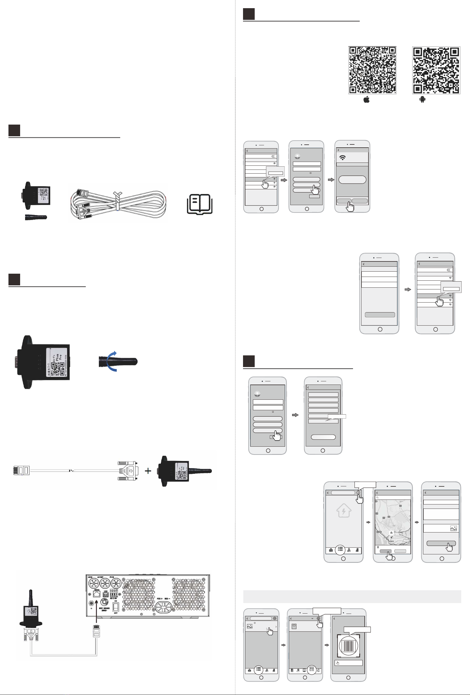
Quick Installation Guide
Wi-Fi Plug Pro
1
3
Tap the WiFi symbol in the upper right-
hand corner of the screen to search for
the WiFi network.
Once your network is located select it
and click confirm
Enter the password for your home
internet. Once you've entered the
password - click DONE in the bottom
right-hand corner
You should see a message reading
"The setting is successful, please wait
for the collector to restart before
connecting to it and operating again."
Once the message goes away, click the
"Connect to WIFI-Data Logger" button
on the screen
3.1 Download APP
1 Scan the QR Code on the right
side and download the APP.
Register
User Name
Passwor d
Confirm P asswo rd
E-mail
Phone Num ber
PN
Register
Datalogger PN
1
2
Go back to your phone's WiFi
Settings and reconnect to your home
internet.
Open the APP, tap the Register button
to enter this page.
According to the prompts, type in the
information to create an account.
4.3
Add Multiple Dataloggers
①Tap the new plant you just created,
and enter its home page.
②Click the Device button on the
bottom of the home page.
1Tap the new plant you just created,
and enter its home page.
Click the DEVICE button on the
bottom of the home page.
Note: One account can create multiple plants and one plant can add multiple dataloggers. If you only have one
datalogger, you could ignore this step.
新建电站
SmartClient
Kee p passw ord
Please en ter use r name
Please en ter pas sword
Login
Wi-Fi Config
Register
Demo>
Create Plants
Pleas e ent er plant’s name
Plant Nam e*
Finish
Plant description
Plant picture
Pleas e inp ut the descript ion t he plant
Plant pic ture
4.2
Create Plant
4.1
Create Account
Plant Name
Cur ren t powe r: 55 .6kW
Daily gene ratio n: 141. 6kWh
Dai ly inco me: ¥15 8.2
Total g enera tion: 3 64.3k Wh
OVE RVIEW LIST MAP ME
Input the Data logge r PN
Datalogger PN
Add Datalogger
Add Datalogger
Device
Device 1
Cur rent po wer: 125kW
Dai ly gene ratio n: 125 kWh
PN:123 456 789
Inf o Map Da ta Ala rm
Devices
3.3
Network Setting
3.2
Connect Wi-Fi Datalogger
Android
iOS
Wireless Router Connection
3.
Create Account And Plant
4.
Location of the plant
Locat ion:B aoan, Shenzhen
Pleas e enter the locatio n of the plant
Confi rm Canc el
新建电站
Create Plant
You don't have
a plant yet.
OVE RVIE W LIST M AP ME
WLAN
CHOOS E A NET WOR K...
W2015
2018LA
WLAN
Eybond 2. 4g
Eybond2 015
W001625 00206 17
Wifi111
Wifi-te st
PASSWORD
12345678
Network Sett ings
Router Name:
Password:
Pleas e con nec t to th e wireless rout er
Setting
Confirm passwo rd:
1
2
3
In the WiFi connection settings of
your phone, select the PN of the
Datalogger you are attempting to
configute (Initial Password:12345678)
Open the APP, Tap the Wi-Fi Config
button.
Then tap the Network Setting
button.
SmartClient
Kee p passw ord
Pleas e enter u ser nam e
Pleas e enter p asswo rd
Login
Wi-Fi Con fig
Regist er
DEMO>
W0016250020617
Please c hoo se a Wi -Fi a nd connec t.
Connected
Netwo rk Di agnose
Netwo rk Se tting
Connect
Wi-Fi Da talogger
WLAN
CHOOSE A N ETW ORK ...
W2015
2018L A
WLAN
Eybon d 2.4 g
Eybon d20 15
W0016 250 020617
Wifi111
Wifi- tes t
PASSWORD
1234567 8
1-1 WIFI Module;1-2 Communication cable;1-3 Instruction book;
Packing Accessories Detail
1.
1-1 1-2 1-3
2.1 Plug antenna into WIFI box
Installation Steps
2.
2.2
Plug communication cable into WIFI Module
2.3 Plug the communication cable (RJ45 head) into the inverter RS232 port (RJ45
Port Type)
+
4
5
2
1 Login to the account and click
the List button on the bottom
of the homepage
2 Tap the + button on the top
right corner of the list page
3 According to the prompts,
type in the information to finish
creating the plant
2
4
Tap the “+” button at the top-right
corner to add the datalogger.
Scan the datalogger PN on the
Wi-Fi Plug Pro, or input it manually.
3
EG4 Electronics
www.eg4electronics.com

Table Of Contents
ABOUT THIS MANUAL....................................................................................................................................................1
Purpose............................................................................................................................................................................. 1
Scope.................................................................................................................................................................................1
SAFETY INSTRUCTIONS............................................................................................................................................... 1
INTRODUCTION...............................................................................................................................................................2
Features............................................................................................................................................................................ 2
Basic System Architecture..............................................................................................................................................2
Product Overview............................................................................................................................................................ 3
INSTALLATION.................................................................................................................................................................4
Unpacking and Inspection..............................................................................................................................................4
Preparation....................................................................................................................................................................... 4
Mounting the Unit............................................................................................................................................................4
Battery Connection..........................................................................................................................................................5
AC Input/Output Connection......................................................................................................................................... 6
PV Connection.................................................................................................................................................................. 8
Final Assembly................................................................................................................................................................. 9
Dry Contact Signal........................................................................................................................................................ 10
OPERATION.................................................................................................................................................................... 11
Power ON/OFF............................................................................................................................................................... 11
Operation and Display Panel....................................................................................................................................... 11
LCD Display Icons......................................................................................................................................................... 12
LCD Setting.................................................................................................................................................................... 14
Display Setting............................................................................................................................................................... 23
Operating Mode Description........................................................................................................................................ 27
Fault Reference Code................................................................................................................................................... 29
Warning Indicator......................................................................................................................................................... 30
BATTERY EQUALIZATION.......................................................................................................................................... 31
LITHIUM BATTERY SETTINGS................................................................................................................................. 33
SPECIFICATIONS..........................................................................................................................................................38
Table 1 Line Mode Specifications................................................................................................................................38
Table 2 Inverter Mode Specifications.........................................................................................................................39
Table 3 Charge Mode Specifications.......................................................................................................................... 39
Table 4 General Specifications.................................................................................................................................... 40
TROUBLE SHOOTING.................................................................................................................................................. 42
Parallel Installation Guide........................................................................................................................................ 47
1. Instruction................................................................................................................................................................. 47
2. Package Contents..................................................................................................................................................... 47
3. Mounting the Unit.....................................................................................................................................................47
4. Wiring Connection.................................................................................................................................................... 48
5. Parallel Operation in Single phase......................................................................................................................... 50
6. Support 3-phase equipment................................................................................................................................... 53
7. Support split phase...................................................................................................................................................55
8. PV Connection........................................................................................................................................................... 56
9. Split-Phase and 3 Phase LCD Setting and Display.............................................................................................. 57
10. Commissioning........................................................................................................................................................ 59
11. Parallel Trouble shooting.......................................................................................................................................60
Typical Application........................................................................................................................................................ 22
Table 5 Parallel Specifications..................................................................................................................................... 41
EG4 Electronics
www.eg4electronics.com

1
ABOUT THIS MANUAL
Purpose
This manual describes the assembly, installation, operation and troubleshooting of this unit. Please read
this manual carefully before installation and operation.
Scope
This manual provides safety and installation guidelines as well as information on tools and wiring.
SAFETY INSTRUCTIONS
WARNING: This chapter contains important safety and operating instructions. Read and
keep this manual for future reference.
1.Before using the unit, read all instructions and cautionary markings on the unit, the batteries and all
appropriate sections of this manual.
2.CAUTION -
To
reduce
risk
of
injury,
charge
only
deep-cycle,
lead
acid, or
Li-Ion type rechargeable
batteries.
Other
types
of
batteries
may
burst,
causing
personal
injury
and
damage.
3.Do not disassemble the unit. When service or repair is required, take it to a qualified service center.
Incorrect re-assembly may result in a risk of electric shock or fire.
4.To reduce risk of electric shock, disconnect all wirings before attempting any maintenance or cleaning.
Turning off the unit will not reduce this risk.
5.CAUTION –
Only
qualified
personnel
should
install
this
device
with a
battery.
6.NEVER charge a frozen battery.
7.For optimum operation of this inverter/charger, please follow required spec to select appropriate
cable size.
8.Be very cautious when working with metal tools on or around batteries. A potential risk exists for a
dropped tool to spark or short circuit batteries / other electrical parts causing an explosion.
9.Please strictly follow installation procedure when disconnecting AC or DC terminals. Please refer to
INSTALLATION section (pg 4) of this manual for details.
10.Fuse is provided as over-current protection for the battery supply.
11.GROUNDING INSTRUCTIONS -This inverter/charger should be connected to a permanent grounded
wiring system. Be sure to comply with local requirements and regulation when installing this inverter.
12.NEVER short AC output or DC inputs. Do NOT connect to the grid with a shorted DC input.
13.Warning!!
Only
qualified
personnel
are
able
to
service
this
device.
If
errors
still
persist
after
following
troubleshooting
table,
please
send
this
inverter/charger
back
to
local
dealer
or
service
center
for
maintenance.
EG4 Electronics
www.eg4electronics.com

2
INTRODUCTION
This is a multi-function inverter/charger, combining the capabilities of an inverter, MPPT solar charger,
and battery charger to offer uninterrupted power support in a portable size. Its comprehensive LCD
display offers user-configurable and easy-accessible button operation including: battery charging current,
AC/solar charger priority, and acceptable input voltage based on different applications.
Features
•
Pure sine wave inverter - <3% THD
•
Built-in MPPT solar controller - 120V to 500V
•
Configurable input voltage range for home appliances and personal computers - 65V to 140VAC
•
Configurable battery charging current based on applications - 30A to 80A
•
Configurable AC/Solar Charger priority.
•
Compatible to utility grid or generator power - 120V
•
Auto restart when AC input is restored
•
Overload/ Over temperature/ Short circuit protection
•
Smart battery charger design for optimized battery performance
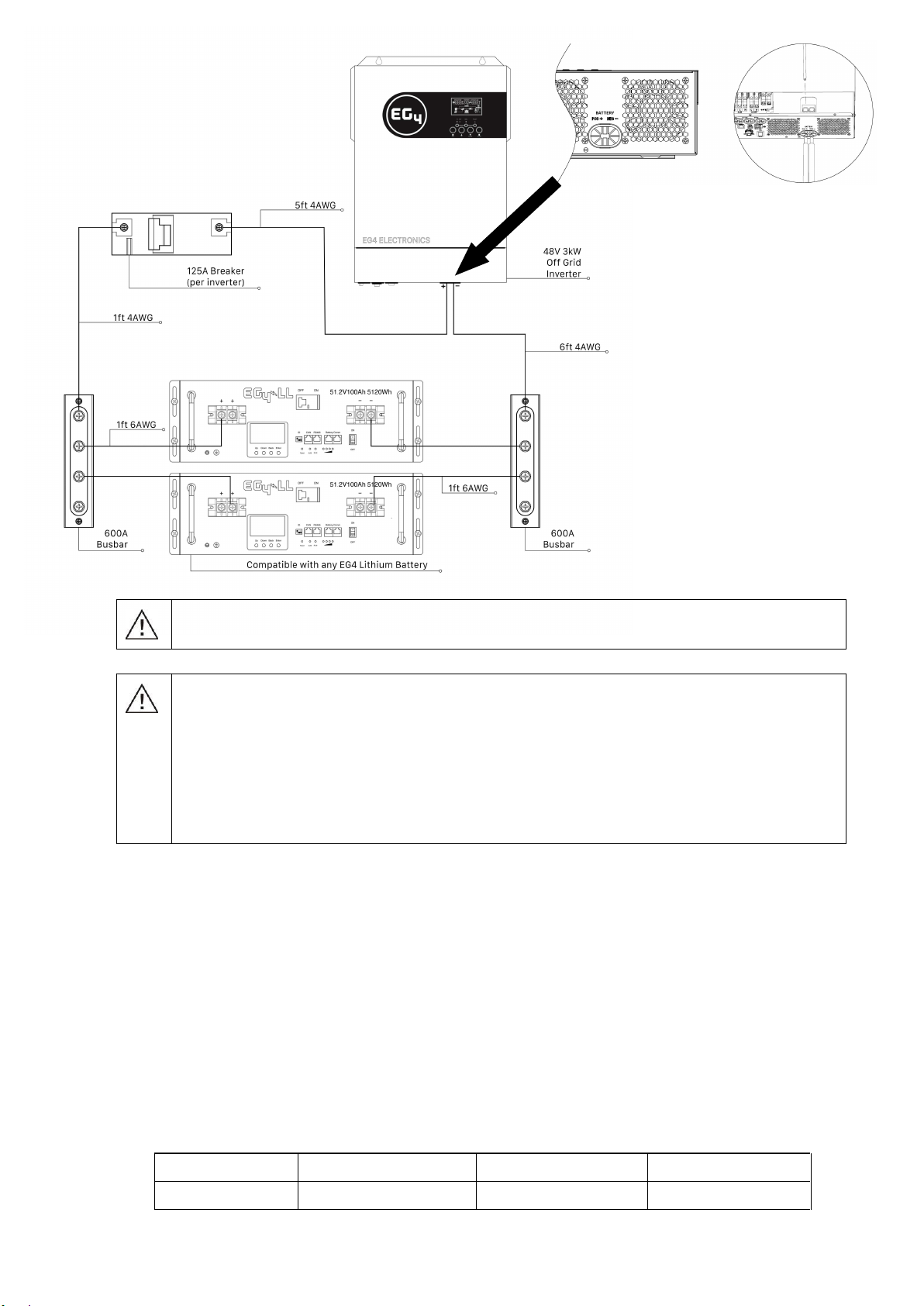
Basic System Architecture
The following illustration shows basic application for this inverter/charger - including the below-listed
devices needed for a complete running system:
•
Generator or Utility
•
48V Battery
•
PV Modules
Consult with your system integrator for other possible system architectures depending on your requirements.
This inverter can power all kinds of appliances in a home or office environment, including compressor based
appliances such as a refrigerator or air conditioner.
Figure 1 Solar Power System
EG4 Electronics
www.eg4electronics.com

3
Product Overview
1.
LCD display
2.
Status indicator
3.
Charging indicator
4.
Fault indicator
5.
Function buttons
6.
Power on/off switch
7.
AC input (L - N)
8.
AC output (L - N)
9.
PV input (500Vdc Max)
10.
Battery input (48V Nominal)
11.
AC Input Circuit breaker
12.
RS232 communication port for
WiFi communication
13.
Parallel communication port (only
for parallel model)
14.
Dry contact (Optional)
15.
USB communication port for PC
Applications
16.
RS485 BMS communication port
17.
Grounding Screw
NOTE: For parallel model installation and operation, please check the parallel installation guide (pg. 47) for details.
EG4 Electronics
www.eg4electronics.com

4
INSTALLATION
Unpacking and Inspection
Before installation, please inspect the unit to be sure that nothing inside the package is damaged. You
should have received the following items:
•WiFi Communications Module
•5' RJ11 to DB9 male RS232 Cable
•4' RJ45 patch cable
Preparation
Before connecting all wiring, please remove the bottom cover by removing two screws as shown below.
Mounting the Unit
Consider the following points before selecting where to install:
Do not mount the inverter on flammable
construction materials.
Mount on a solid surface
Install this inverter at eye level in order to allow
the LCD display to be read at all times.
The ambient temperature should be between 0°C
to 55°C (-15°F to 131°F) to ensure optimal operation.
The recommended installation position is to be adhered
to the wall vertically.
Be sure to distance other objects and surfaces as
shown in the right diagram to guarantee sufficient heat
dissipation and to have enough space for removing wires.
SUITABLE FOR INDOOR MOUNTING ON
CONCRETE OR OTHER NON-COMBUSTIBLE
SURFACE ONLY.
•EG4 3000EHV-48 Inverter
•User manual
•Battery BMS Cable
•125A DC Breaker
•6" DIN Rail
•6' Red and Black 4AWG Battery Cable
EG4 Electronics
www.eg4electronics.com

5
Install the unit by screwing three screws. It’s recommended to use M4 or M5 screws.
Battery Connection
CAUTION:
For
safety
operation
and
regulation
compliance,
it is
recommended
that
a
separate
DC
over-current
protector
or
disconnect
device is installed
between
battery
and
inverter.
Please
refer
to
typical
amperage listed below
for
required
fuse
or
breaker
size.
Stripping Length:
WARNING!
We recommend all wiring be performed by a licensed professional.
WARNING!
It is
very
important
for
system
safety
and
efficient
operation
to
use the
appropriate
cable size
for
battery
connection.
To
reduce
risk
of
injury,
please
use
the
recommended
cable, stripping
length(L2),
and tinning length(L1)
in the table
below.
Recommended battery cable, stripping length (L2), and tinning length(L1):
Model Maximum
Amperage
Battery
capacity
Wire Size L1
(mm/in)L 2
(mm/in)
Torque
value
3000EHV-48 80A100AH 4AWG/25 3/0.1" 18/0.7" 2~ 3 Nm
Please follow the following steps to implement battery connection:
1.
Remove insulation sleeve 18 mm for positive and negative cables based on recommended stripping
length.
2.
Connect all battery packs as unit requires, and use recommended battery capacity.
3.
Insert battery cable to the battery connector of inverter and make sure the bolts are tightened
with torque of 2-3 Nm. Make sure polarity at both the battery and the inverter/charge is
correctly connected and battery cables are tightly screwed to the battery connector.
Recommended
Wire Size
Wire Length
6'/1.8m up to 15'/4.6m
Wire Size
AWG/mm2
(7 7/8th Inches)
Please Note: Maximum current drawn by the inverter is 80A. If using EG4 Batteries, the maximum
output is 100A. A 125A breaker is utilized to support maximum battery current of 100A. If using
batteries other than EG4, please consult the manufacturer's manual to ensure proper breaker size.
EG4 Electronics
www.eg4electronics.com
6
WARNING: Shock Hazard
Installation must be performed with care due to high battery voltage in series.
CAUTION!! Do not place anything between the flat part of the inverter terminal. Overheating
may occur.
CAUTION!! Do not apply anti-oxidant substance on the terminals before terminals are
connected tightly.
CAUTION!! Before making the final DC connection or closing DC breaker/disconnector, be sure
positive (+) is connected to positive (+) and negative (-) is connected to negative (-).
AC Input/Output Connection
CAUTION!!
Before
connecting
to
AC
input
power
source,
please
install
a
separate
AC
breaker
between
inverter
and
AC
input
power
source.
This
will
ensure
the
inverter
can
be
securely
disconnected
during
maintenance
and
fully
protected
from AC input
over
current.
Recommended
specification
of
AC
breaker
is
50A
on the input and 30A on the output.
CAUTION!!
There
are
two
terminal
blocks
with
“IN”
and
“OUT”
markings.
Please
do
NOT
mis-connect
input
and
output
connectors.
WARNING!
We recommend all wiring be performed by a licensed professional.
WARNING!
It is
very
important
for
system
safety
and
efficient
operation
to
use
appropriately sized
cable
for
AC
input
connection.
To
reduce
risk
of
injury,
please
use
the
proper
recommended
cable
size
as
below.
Suggested cable requirement for AC wires
Model Gauge*Torque Value
3000EHV-48 10AWG up to 32'/16.5m 1.4~ 1.6Nm
AC Breaker**
50A Input/ 30A Output
*120V system, 3% max drop, assuming open air. AC output is 25A.
**AC bypass is 25A + 20A charge = 45A with a 60A breaker
EG4 Electronics
www.eg4electronics.com

7
Please follow below steps to implement AC input/output connection:
1.
Before making AC input/output connection, be sure to open DC protector or disconnecter FIRST.
2.
Remove insulation sleeve 10mm for six conductors. And shorten phase L and neutral conductor N 3 mm.
3.
Insert AC input wires according to polarities indicated on terminal block and tighten the terminal
screws. Be sure to connect PE protective conductor ( ) first.
→Ground (Green) L→LINE (Black) N→Neutral (White)
WARNING:
Be sure that AC power source is disconnected before attempting to hardwire it to the unit.
4.
Then, insert AC output wires according to polarities indicated on terminal block and tighten terminal
screws. Be sure to connect PE protective conductor ( ) first.
→Ground (Green)
L→LINE (Black)
N→Neutral (White)
Important to Note:
When the inverter is working in PV mode, battery mode, or standby mode, the output neutral
is connected to the ground of AC output (neutral/ground bonded).
When the inverter is working in AC mode, neutral of output is disconnected to grounding of AC
output and connected to neural of AC input.
5.
Make sure the wires are securely connected.
CAUTION: Important
Be sure to connect AC wires with correct polarity. If L and N wires are reversed, it may cause a
utility short-circuit when these inverters are in parallel operation.
CAUTION: Appliances such as air conditioners require at least 2~3 minutes to restart because to have
enough time to balance the refrigerant gas. If a power outage occurs and recovers in a short time, it
may cause damage to your connected appliances. To prevent this damage, please check the appliance
manufacturer for time-delay start function before installation. The inverter/charger will trigger an overload
fault and cut off the output to protect your appliance which may cause internal damage to the appliance.
EG4 Electronics
www.eg4electronics.com
8
PV Connection
CAUTION:
Before
connecting
to
PV
modules,
please
install a
separate
DC
circuit
breaker
between the
inverter
and
PV
modules.
WARNING!
We recommend all
wiring
be
performed
by
a licensed professional.
WARNING!
It is
very
important
for
system
safety
and
efficient
operation
to
use
appropriate
cable
for
PV
module
connection.
To
reduce
risk
of
injury,
please
use
the
proper
recommended
cable
size
as
below.
Model Maximum Draw Cable Size*Torque
3000EHV-48 18A 10 AWG up to 50'/15.2m 1.4~1.6 Nm
PV Module Selection:
When selecting proper PV modules, please be sure to take into account that the open circuit Voltage
(Voc) of PV modules should not exceed max. PV array open circuit voltage of inverter.
Solar Charging Mode
INVERTER MODEL 3000EHV-48
Max. PV Array Open Circuit Voltage 500DC
PV Array MPPT Voltage Range 120VDC~450VDC
EXAMPLE:
Using a 330W
PV
module and
considering the
above
two system
parameters --
the
recommended
module
configurations
would be as follows:
Solar Panel Spec.
- 330W 60 cell
- Vmp: 33.25Vdc**
-VmpTC: -0.43%/C
- Imp: 9.925A
- Voc: 40.35Vdc**
-VocTC: - 0.31%/C
- Isc: 10.79A
SOLAR INPUT*** Quantity of
panels
Total input
power
Inverter
Model
Min in series: 5 pcs, max. in series: 10 pcs
6 pcs in series 6 pcs 1980W 3000EHV-48
8 pcs in series 8 pcs 3300W 3000EHV-48
10 pcs in series 10 pcs 3300W
6 pieces in series and 2 sets in parallel 12 pcs 3960W
8 pieces in series and 2 sets in parallel 16 pcs 5280W
3000EHV-48
3000EHV-48
3000EHV-48
* Assuming 10% voltage drop free air
** VOC
max @ -25C/-14F = 46.6Vdc and Vmp min @ 40C/104F Ground mount =
27.5Vdc
***Calculate panel configuration for your specific location and panel specifications
Recommended Panel Configuration
When selecting proper PV modules, please be sure to consider the following parameters:
1. Temperature adjusted open circuit voltage (Voc) of PV modules not to exceed maximum PV
array open circuit voltage of the inverter.
2. Temperature adjusted voltage at maximum power (Vmp) of PV modules should be higher than
the startup voltage of the inverter.
EG4 Electronics
www.eg4electronics.com
9
PV Module Wire Connection:
Please follow below steps to implement PV module connection:
1.
Remove insulation sleeve 10 mm/0.4" for positive and negative conductors.
2.
Check correct polarity of connection cable from PV modules and
PV input connectors. Then, connect positive pole (+) of connection cable
to positive pole (+) of PV input connector. Connect negative pole (-) of
connection cable to negative pole (-) of PV input connector.
3.
Make sure the wires are securely connected.
Final Assembly
After connecting all wirings, please put bottom cover back by screwing in the two screws as shown below.
EG4 Electronics
www.eg4electronics.com

10
Dry Contact Signal
There is one dry contact (3A/250VAC) available on the rear panel which can be used to deliver signal to
external device when battery voltage reaches warning level.
Unit Status Condition Dry contact port:
NC & C NO & C
Power Off Unit is off and no output is powered. Close Open
Power On
Output is powered from Utility. Close Open
Output is
powered
from
Battery or
Solar.
Program 01
set as Utility
Battery voltage < Low DC warning
voltage Open Close
Battery voltage > Setting value in
Program 13 or battery charging
reaches floating stage
Close Open
Program 01
is set as
SBU or SUB
or Solar
first
Battery voltage < Setting value in
Program 12 Open Close
Battery voltage > Setting value in
Program 13 or battery charging
reaches floating stage
Close Open
EG4 Electronics
www.eg4electronics.com
11
OPERATION
Power ON/OFF
Once the unit has been properly installed and the batteries are connected well, simply press the On/Off switch
(located on the button of the case) to turn on the unit.
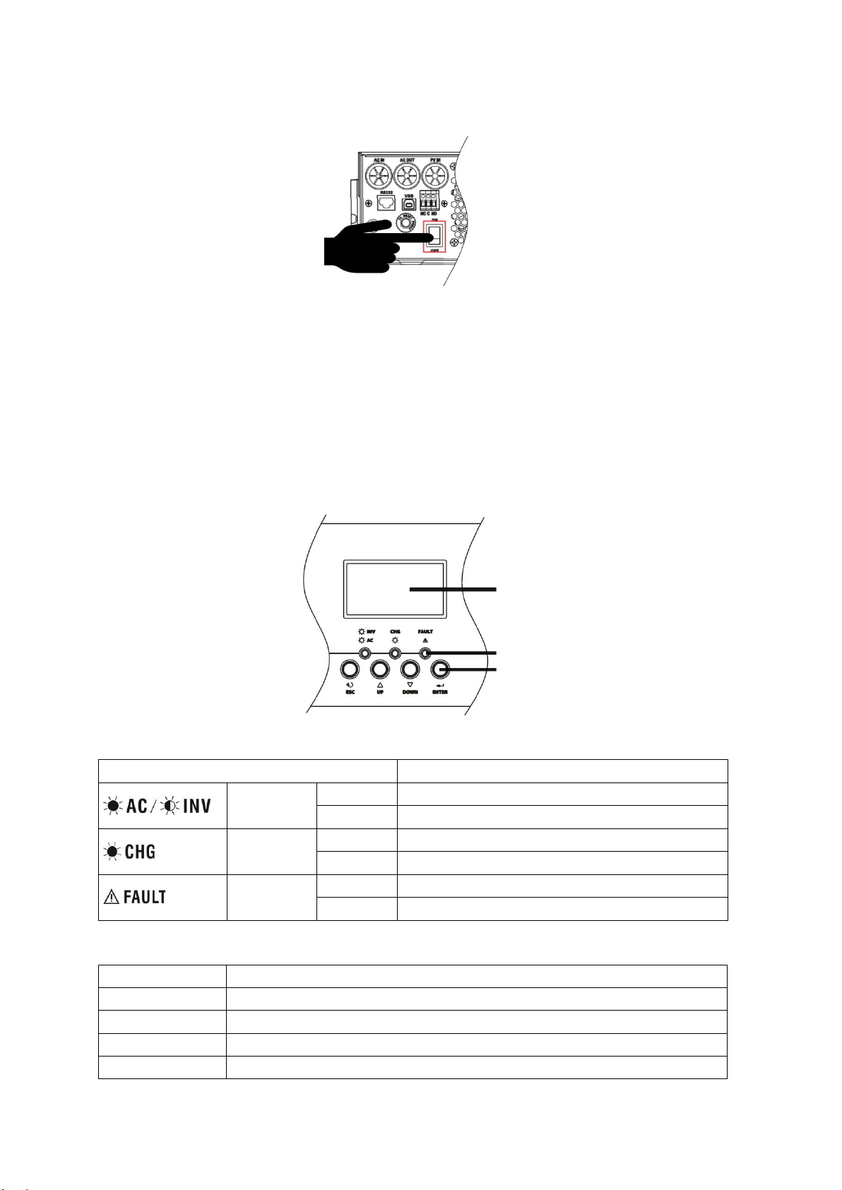
Operation and Display Panel
The operation and display panel, shown in the below chart, is on the front panel of the inverter.
It includes three indicators, four function keys, and a LCD display which indicates the operating status,
input/output power information, et cetera.
LCD display
LED indicators
Function keys
LED Indicator
LED Indicator Messages
Green Solid On Output is powered by utility in Line mode.
Flashing Output is powered by battery or PV in battery mode.
Green Solid On Battery is fully charged.
Flashing Battery is charging.
Red Solid On Fault occured in the inverter.
Flashing Warning condition occured in the inverter.
Function Keys
Function Key Description
ESC To exit setting mode
UP To go to previous selection
DOWN To go to next selection
ENTER To confirm the selection in setting mode or to enter setting mode
EG4 Electronics
www.eg4electronics.com
12
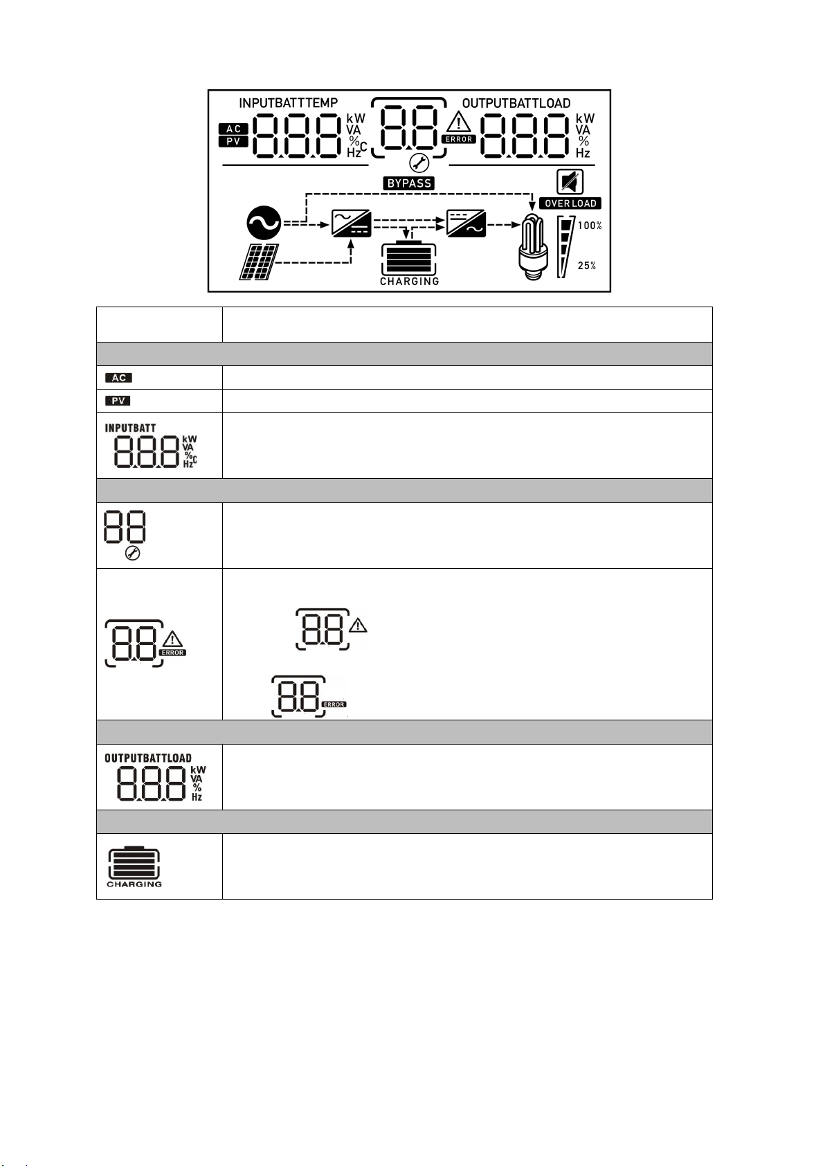
LCD Display Icons
Icon Function description
Input Source Information
Indicates the AC input.
Indicates the PV input
Indicate input voltage, input frequency, PV voltage, battery voltage and
charger current.
Configuration Program and Fault Information
Indicates the program settings
Indicates the warning and fault codes.
Warning: flashes the warning code.
Fault: lights the fault code
Output Information
Indicates the output voltage, output frequency, load percentage, load in
VA, load in Watt and discharge current.
Battery Information
Indicates battery level: 0-24%, 25-49%, 50-74% and 75-100% for each bar
in battery mode and charging status in line mode.
EG4 Electronics
www.eg4electronics.com

13
Load Information
Indicates overload.
Indicates the load level: 0-24%, 25-49%, 50-74% and 75-100%.
0%~24% 25%~49% 50%~74% 75%~100%
Mode Operation Information
Indicates unit is connected to the grid.
Indicates unit is connected to the PV panel.
Indicates load is directly connected to the grid.
Indicates the utility charger circuit is operational.
Indicates the DC/AC inverter circuit is operational.
Mute Operation
Indicates unit alarm is disabled.
EG4 Electronics
www.eg4electronics.com

14
LCD Setting
After pressing and holding the ENTER button for 3 seconds, the unit will enter setting mode. Press UP or DOWN
button to select setting programs. Then, press ENTER button to confirm the selection or ESC button to exit.
Setting Programs:
Program Description Selectable option
01 Output source priority: To
configure load power
source priority
Solar first
Solar energy provides power to
the loads as first priority.
If solar energy is not sufficient to
power all connected loads, battery
energy will supply power to the
loads at the same time. Utility
provides power to the loads only
when one or all of the following
conditions is in play:
-
Solar energy is not available
-
Battery voltage drops to either
low-level warning voltage or the
setting point in
program
12.
Utility first (default)
Utility will provide power to the
loads as first priority.
Solar and battery energy will
provide power to the loads only
when utility power is not
available.
SBU priority
Solar energy provides power to
the loads as first priority.
If solar energy is not sufficient to
power all connected loads, battery
energy will supply power to the
loads at the same time.
Utility provides power to the loads
only when battery voltage drops to
either low-level warning voltage or
the setting point in program 12.
SUB priority
Solar energy is charged first and
then power to the loads.
If solar energy is not sufficient to
power all connected loads, utility
energy will supply power to the
loads at the same time.
EG4 Electronics
www.eg4electronics.com
Other manuals for 3000 EHV-48
1
Table of contents
Other EG4 Inverter manuals


