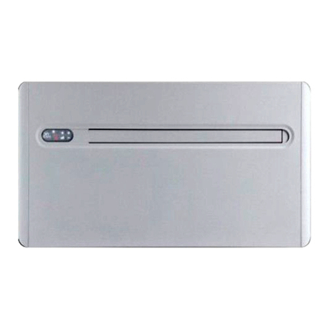
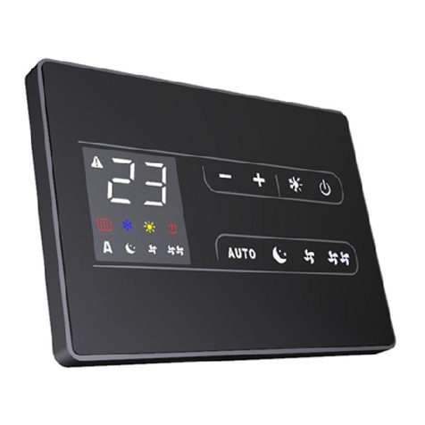
Innova Filomuro SLW 400 User manual

something new in the air
SLW
EN
Installation and user manual
something new in the air

2
Compliance
We would first of all like to thank you for having chosen one of our products.
We are sure you will be happy with it because it represents the state of the art in the technology of
home air conditioning.
By following the suggestions contained in this manual, the product that you have purchased will
operate without problems giving you optimum room temperatures with minimum energy costs.
This unit complies with the following European Directives:
• Low voltage 2014/35/UE; • Electromagnetic compatibility 2014/30/UE ;
The pictograms in the next chapter provide the necessary
information for correct, safe use of the machine in a rapid,
unmistakable way.
Symbols
U
User
- Refers to pages containing instructions or information
for the user.
I
Installer
- Refers to pages containing instructions or information
for the installer.
S
Service
- Refers to pages containing instructions or information
for the installer TECHNICAL CUSTOMER SERVICE.
Editorial pictograms
Safety pictograms
Generic danger
- Signals to the personnel that the operation described
could cause physical injury if not performed according
to the safety rules.
Danger of high voltage
- Signals to the personnel that the operation described
could cause electrocution if not performed according
to the safety rules.
Danger due to heat
- Signals to the personnel that the operation described
could cause burns if not performed according to the
safety rules.
Prohibition
- Refers to prohibited actions.
Innova S.r.l

3
EN
1.1Table of contents
Symbols 2
GENERAL 5
General warnings 5
Essential safety rules 5
Product range 6
Rated technical specifications 6
Filomuro
overall dimensions 7
Dimensions and weight during transportation 7
INSTALLATION 8
Unit placement 8
Installation procedure 8
Installation clearances 8
Opening of aesthetic parts for installation of equipment and connections 9
High wall mount or flush with floor 11
Installation template (measured) 14
Hydraulic connections 16
Condensate drain 18
Filling the plant 19
Air exhaust when filling the system 19
Wiring 20
CONTROL PANEL INSTALLATION AND CONNECTION 21
ER0689 board connections 21
ER0690 connections 22
Fitting the wall-mounted remote control panel ECA649 23
Spring clamps -AB+ and CP connection 24
CP presence contact input connection 24
ECA649 connections 25
Diagram for BB0698 connections with 3-speed thermostats 26
BB0698 connection with 3-speed thermostats 27
LED signals 27
Water probe management with 3-speed thermostat 28
Diagram for BB0699 connections with 0-10 V DC thermostats/signals 29
BB0699 connections with 0-10 V thermostats 29
LED signals 29
BB0698 board + thermostat BM1151 Wiring diagram 30
BB0698 board + timer BM0152 Wiring diagram 31
OPERATING INSTRUCTIONS WITH REMOTE CONTROL (for command 0689) 32
Warnings 32
Management of the unit with the touch-screen and remote control 32
Functional description 33
Troubleshooting 36
INSTRUCTIONS FOR USE WITH WALL-MOUNTED CONTROL PANEL 37
SMART TOUCH wall-mounted electronic control panel with room probe 37
Display 37
Keys function 37
General start-up 38
Activation 38
Heating / cooling operating mode set-up 38
Stand By 38
Table of contents

4
Temperature selection 38
Automatic operation 39
Silent operation 39
Night function 39
Operation at maximum ventilation speed 39
Key locking 39
Minimum brightness reduction 39
Deactivation 40
Room temperature probe offset adjustment 40
Long term shut-down 40
Error signals 40
Electronic board with continuous modulation for remote thermostat connection 41
LED Signals (ref. A) 41
ROUTINE MAINTENANCE 42
Maintenance 42
External cleaning 42
Cleaning the air suction filter 43
Suggestions for power saving 44
TROUBLESHOOTING 45
Troubleshooting table 45

5
EN
1.1
1.2
General warnings
Essential safety rules
After unpacking, make sure that all the components are
present. If not, contact your vendor who sold the device
to you.
Only qualified installer companies are
authorised to install our devices. After having
completed installation, the installer will issue a
declaration of conformity to the plant manager, as
required by the applicable standards and the guidelines
provided by contructor's instruction manual supplied
with the device.
These devices have been designed for room
heating and/or air conditioning and must be
used as intended and compatibly with their performance
levels.
Any contractual and extra-contractual liability of
constructor for harm caused to persons, animals or
property by installation errors, improper adjustments,
maintenance or use is excluded.
If water leaks out of the device, set the main switch to
"Off" and close the water taps.
Contact our Technical Customer Service as soon as
possible or professionally qualified staff and do not
personally attempt to fix the problem.
If the device is to remain out of service for a prolonged
period, make sure you carry out the following operations:
- Set the main system switch to "Off"
- Close the water taps
- If there is danger of frost, make sure that you have
added anti-freeze liquid into the circuits, or drain out the
system otherwise.
A temperature that is too low or too high is harmful to
health and is an unnecessary waste of energy.
Avoid direct contact with the air flow over an extended
period.
Avoid keeping the installation premises closed for a long
time. Frequently open the windows to ensure proper air
circulation.
This instruction manual forms an integral part of the
device and therefore must be carefully preserved and
must ALWAYS travel with it, even if you transfer the
device to another owner or relocate it to other premises.
If the manual gets damaged or lost, request a copy to
your local Technical Customer Service.
All repair or maintenance interventions must be performed
by the technical service department or by professionally
qualified personnel as foreseen in this booklet. Do not
modify or intervene on the appliance as this could create
dangerous situations and the manufacturer will not be
responsible for any damage caused.
Avoid contact: danger of burns.
Please keep in mind that the use of products powered
by electricity and water call for operators to comply with
certain essential safety rules:
It is forbidden to children and unassisted disabled
persons to use the device.
It is forbidden to touch the device barefoot or with wet or
damp body parts.
It is forbidden to clean the device before having
disconnected it from the mains by setting the main
switch of the system to "off".
It is forbidden to modify the safety or adjustment devices or
adjust without authorisation and indications of the manufacturer.
It is forbidden to pull, unplug or twist the device’s electric
cables, even if it is disconnected from the mains.
Do not introduce objects and substances through the air
inlet and outlet grilles.
It is forbidden to open the access doors of the device’s
internal parts without first having set the main switch of
the system to "off".
It is forbidden to dispose of, or leave in the reach of
children, the packaging materials which could become
a source of danger.
GENERAL

6
S
I
U
GENERAL
1.3
1.4
Product range
The cooler-radiators of the
Filomuro
range are available in
the SLW version for high wall mount installation or flush with
the floor in special circumstances.
The terminal is available in three different performance levels
and sizes, all with two-pipe configuration.
It is forbidden to climb with your feet on the device and/
or to place any kind of object on top of it.
The external components of the device can reach
temperatures of more than 70 °C.
Rated technical specifications
TECHNICAL DATA (DC)
filomuro
SLW 400 SLW 600 SLW 800
Coil water content L 0.54 0.74 0.93
Maximum operating pressure bar 10 10 10
Maximum water inlet temperature °C 80 80 80
Minimum water inlet temperature °C 4 4 4
Hydraulic connections "
Eurokonus 3/4 Eurokonus 3/4 Eurokonus 3/4
Power supply voltage V/ph/Hz 230/1/50 230/1/50 230/1/50
Maximum power consumption at maximum speed W 17.6 19.8 26.5
Maximum power consumption at minimum speed W 4.8 5.1 5.8
Length mm 902 1,102 1,302
Height mm 318 318 318
Depth mm 128 128 128
Weight kg 14 16 19

7
EN
S
I
U
GENERAL
1.5
SLW
1.6
L
P
H
Dimensions and weight during transportation
Filomuro
overall dimensions
2 pipes
Packaging
Dimensions
Weight
M.E. SLW 400 SLW 600 SLW 800
kg 15 17 20
L mm 1,035 1,235 1,435
H mm 490 490 490
D mm 213 213 213
U.M.
SLW 400 SLW 600 SLW 800
L mm 902 1,102 1,302
Dimensions

8
S
I
U
INSTALLATION
2.1
2.2
2.3
INSTALLATION
Unit placement
Installation procedure
Avoid installing the unit near:
- areas exposed to direct sunlight;
- heat sources;
- in damp areas and areas in which the unit can come into
contact with water;
- in environments with oil mists;
- in environments subject to high frequencies.
Make sure that:
- the wall on which you intend to install the unit has an
appropriate structure and capacity;
- the wall surface is not crossed by pipelines or power lines;
- the wall is perfectly level;
- there are no obstructions nearby that could compromise the
inlet and outlet airflow;
- the wall on which you are installing the unit is (if possible) an
external perimeter wall, in order to allow condensate drain
outside the premises;
- air flow is not directed towards by-standers.
The assembly steps described below and their drawings
refer to a version of the machine with connections on the
right side.
For ideal installation and performance levels, carefully
follow the instructions in the manual. Failure to do so may
cause system malfunctions and automatically voids the
warranty, and relieves the constructor of any harm caused
to persons, animals or property.
Installation clearances
The figure shows the minimum distances required of the fan
coil from the walls and furniture on site.

9
EN
S
I
U
INSTALLATION
2.4
A
B
A
B
B
A
Opening of aesthetic parts for installation of equipment and connections
- Remove the side panels by unthreading them upwards
as shown in the figure below;
- Remove the 6 hex screws present on the sides of the
front panel;
- Remove the aesthetic front panel as shown in the figure;
side panels
aesthetic front panel

10
S
I
U
INSTALLATION
Aupper grille
Bside panels
B
A
B
- Remove the upper grille by unthreading it in your direction
and lifting it upwards, as shown in the figure;
- remove the side panels by lifting them upwards;

11
EN
S
I
U
INSTALLATION
2.5
A
B
DC
High wall mount or flush with floor
• For smooth installation, especially if you want to set-up
the system before you install the device, we recommend
installing a built-in cistern, as shown in the figure;
• If you do not complete installation of the device when
installing the cistern, leave the water and condensate
drain pipes hanging loose, so that you can later make
the connections without joints;
• When you finally install the device, it will be possible to
connect the cooler-radiator with a 90° fitting and socket
with eurokonus connection;
• another option if you can comfortably bend the pipeline
(which will depend on the depth of the installed cistern)
is to install the eurokonus connection inside the pipeline;
• pay attention to the tilt angle of the condensate drain
pipe, which must rest be laid on the lowermost part of
the cistern so that the pipe’s height never exceeds the
height of the cooler-radiator drain connection;
• for the installation heights, refer to the installation
template supplied with the device and which is shown in
the following pages.
A
built-in cistern
B
connecting water pipelines
C
condensation drainage pipe
D
filomuro
cooler-radiator

12
S
I
U
INSTALLATION
A B
A AB
1.
3.
2.
5.
G
G
6. NO
1. Use the paper template shown in full scale on the next
page and trace the position of the two fixing brackets on
the wall.
2. Drill a hole using a proper tip and insert the plugs (2
per bracket) then attach the two brackets. Do not over-
tighten the screws so that you can adjust them with a
spirit level.
3. Firmly fasten the brackets by tightening the four screws.
4. Check stability by moving the brackets to the right and
left, up and down.
5. Assemble the unit, making sure it fastens properly onto
the brackets and that it is stable.
6. Make sure the tilt angle of the cooler-radiator matches
the measure shown in the figure below.
6. OK, max. tilt 1°
plugs brackets

13
EN
S
I
U
INSTALLATION

14
S
I
U
INSTALLATION
2.6 Installation template (measured)

15
EN
S
I
U
INSTALLATION

16
S
I
U
INSTALLATION
2.7
U.M. 400 600 800
mm 14 16 18
G3
A
OUT
IN
C
Hydraulic connections
No electrical connections are necessary if you opt for the
2-way manual valve.
Simply connect the pipeline to the delivery and return lines
as shown in the figure, with the delivery line at the bottom;
Afan coil
Cthermoelectric motor
IN water inlet pipe fitting
OUT water outlet pipe fitting
The engineer is responsible for choosing the right water lines
and their size, in accordance with good installation practices
and the applicable laws, keeping in mind that under-sized
pipelines lead to poor system operation.
To make the connections:
- position the water lines
- tighten the connections using the "wrench against
wrench" method
- check for any fluid loss
- apply a lining to the connections (use proper insulating
material)
The hydraulic lines and fittings must be thermally insulated.
Avoid partial insulation of the pipes.
Avoid over-tightening the pipes to avoid damage to the
insulation.
To ensure water tightness of the threaded connections, use
hemp and green paste; the use of teflon tape is recommended
if you have poured anti-freeze liquid in the water circuit.
Carefully check that the insulation is tight, in order to prevent
the formation and dripping of condensate.
Pipeline diameter
Connection of the fain coil flush with the wall with a 2-way manual valve (code I20686)

17
EN
S
I
U
INSTALLATION
OUT
A
IN
A
C
B
OUT
IN
C
B
Afan coil
Belectric cable entry hole
Cthermoelectric motor
IN water inlet pipe fitting
OUT water outlet pipe fitting
Connect the pipeline to the delivery and return lines as shown
in the figure, with the delivery line at the top;
Comply with the requirements for electrical connections, as
described in para. 2.13
Connect the filomuro cooler-radiator to the 3-way diverter valve unit with thermo-electric
motor (V30688)
Connection of the fain coil flush with the wall with a 2-way valve and thermoelectric
command (V20687)

18
S
I
U
INSTALLATION
2.8
A
B
B
ø14mm
A
Condensate drain
The condensate drain network must be sized appropriately
(minimum inner pipe diameter: 14 mm) and the pipeline
positioned so that it maintains a consistent slope along the
line (never less than 1%). The drain pipe connects directly to
the drain pan installed at the bottom on the side panel under
the hydraulic connections.
- If possible, make the condensate liquid flow directly onto
a gutter or into a "white water" drain.
- If the liquid is discharged into a sewer, we recommend
that you install a trap-vent to prevent bad odours from
rising back up into the building. The curve of the trap
must be lower than the condensate tray.
- If you need to drain the condensate into a container, it
must remain open and the pipe must not be immersed in
water to prevent adhesion and back-pressure that would
obstruct free flow.
- If the drain pipe has to overcome a gap in height due to its
particular installation which would obstruct condensate
flow, remember to install a pump:
These pumps are commonly available on the market.
However, it is advisable that after installing the pump you
check proper flow of the condensate liquid, pouring it in very
slowly (about 1/2 l of water in about 5-10 minutes) into the
drain pan.
Connect the drain connection of the drain pan that collects
the condensate fluid to a hose and tighten it properly. Make
sure the drip-guard extension is present and that it has been
properly installed.
drain connection
liquid drain pipe
Condensate drain pipe assembly

19
EN
S
I
U
INSTALLATION
A
2.9
2.10
A
Coil vent
Filling the plant
Air exhaust when filling the system
When starting the system, make sure that the
lock-shield on the hydraulic unit is open. If there
is a power black-out and the thermal valve
is already running, use its cap to press the valve shutter and
open it.
- Open all the system’s shut-off devices (whether manual
or automatic);
- Start filling the system by slowly opening the water tap;
- With the aid of a screwdriver, work the vent on the
uppermost coil connection (see figure below);
- When water begins to leak out of the breather valves,
close them and continue to fill the system (as per the
rated specifications).
Check the tightness of the gaskets.
We recommend that you repeat this operation whenever
the device has been running for a few hours and that you
regularly check the system’s pressure.
A
B
B
A
Pay attention to the tilt of the condensate drain pipe when it
channels condensate outside the premises as shown in the
figure.
fan coil
condensate drain pipe

20
S
I
U
INSTALLATION
2.11 Wiring
• Access the electrical parts as described in para. 2.4.
• An on/off switch with delayed fuses or an automatic
circuit breaker (2A) must be installed to supply power to
the system.
• Because the wiring features a suppression filter, as
required by the applicable laws and standards, which
naturally induces micro-dispersion on the ground, it is
best to install selective circuit breakers upstream of the
system.
• For safety reasons, the on/off switch referred to above
should be installed near the device or at any rate in open
view.
• The power cables must be equipped with copper
conductors having the following unitary sections (the
values indicated refer to a maximum line length of 15
mm). The cables must be appropriate for the type of
installation, in accordance with the applicable CEI
standards.
U.M. SLW 400 SLW 600 SLW 800
Power conductor (phase + neutral) mm21.5 1.5 1.5
protective conductor section G/V mm21.5 1.5 1.5
This manual suits for next models
2
Table of contents
Other Innova Inverter manuals

Innova
Innova 10 HP DC User manual

Innova
Innova 2.0 15HP User guide

Innova
Innova AirLeaf ECB649 User manual

Innova
Innova 2.0 User manual

Innova
Innova EB0644 User manual

Innova
Innova SL User manual

Innova
Innova AirLeaf ECA644 User manual

Innova
Innova Air Leaf ECA644 User manual

Innova
Innova Air Compact 4M User manual

Innova
Innova AirLeaf ECA644 User manual