1 Safety instructions
Nixie clock is an electrical device and cautious handling must be assured. In spite of the relatively
low voltage board power supply, a high voltage is present onboard. It can generate voltages
exceeding 200V and can cause electrical shock if handled inappropriately. Keep in mind that nixie
tubes may be disabled during night time but the clock can wake up at any time. Therefore do not
touch any component or soldering point when power is on. Safe assembling, connecting and
operation of this clock are the users’ responsibility. Keep the clock away from children.
The NCV2.1 nixie clock's circuits and software (firmware) may not be reverse engineered, copied
or used commercially without written permission.
2 Assembling
2.1 Logic board assembling
Start by fitting 0,25W resistors since they're the lowest. Then fit the diodes. Double check the
polarity of any polarity sensitive device before soldering. Then assembly all other components
height wise. If you want to experiment with your board or upgrade PICmicro with a newer firmware
in the future, you may consider to use the sockets for the ICs (sockets are optional and are not
provided along with kit. You may obtain them in your local store).
Do not use solder with acid, instead use colophony or any other not electrical conductive solder
resin. Set the soldering iron at appropriate temperature to avoid “cold soldering”. Do not heat any
point for more than 3 seconds, otherwise you risk to damage the electronic components and printed
circuit board.
After successful assembly set high voltage using R26 trimmer, measure the voltage across C6
capacitor. Set the voltage to 160V for IN-14 nixie tubes and 170V for IN-18 nixie tubes. Check
power supply temperature after 10 minutes of operate, if switching transistor (M1 – IRF640) and/or
inductor are very hot set lower voltage.
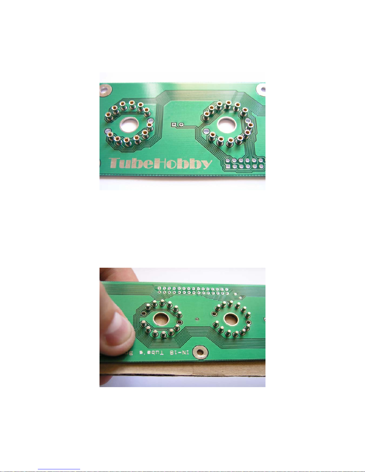
For IN-18 tube's board, 2.2K anode resistors (R15, R17, R18, R19, R20, R21) should be used.
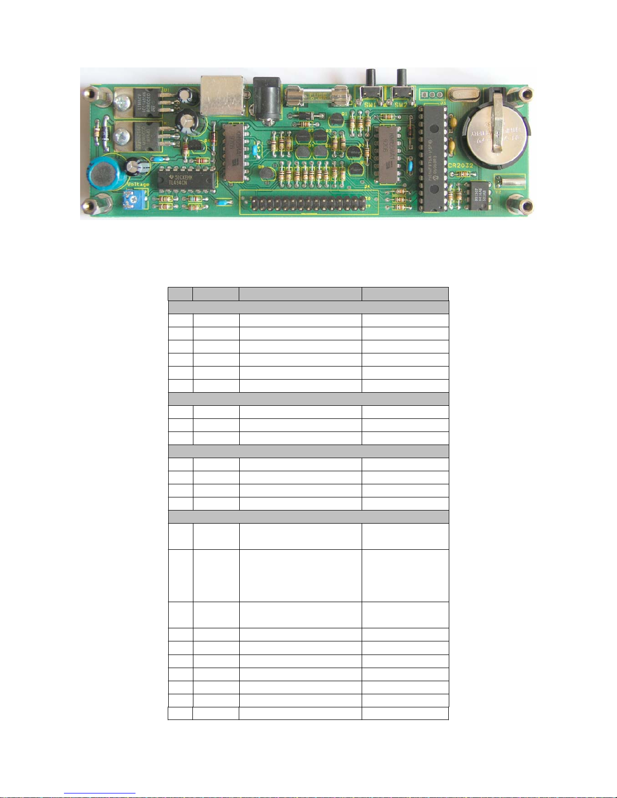
Fig. 1. The logic board's silk screen layer