Tucker GTR S Instruction Manual

1
GTR S / ST AND GTR SS / ST
SIDE BURNER
ASSEMBLY, INSTALLATION AND OPERATING
INSTRUCTION MANUAL
IMPORTANT –PLEASE READ ALL INSTRUCTIONS BEFORE
YOU ASSEMBLE, INSTALL OR OPERATE THIS APPLIANCE.

2
IMPORTANT
Tucker side burners are approved for outdoor use only
Do not use indoors or in any enclosed area.
Always turn off gas supply when you finish using this
appliance.
Always use your barbecue and side burner on a level
surface.
Attend an operating side burner at all times as oil and fat
can be highly flammable.
Damage from fat and grease fires is not covered by
warranty.
Retain this manual for future reference
WARNINGFOR YOUR SAFETY
FOR YOUR SAFETY
If you smell gas:
1. Shut off gas to the appliance.
2. Extinguish any open flame.
3. Open the lid or hood.
4. If odour continues, immediately call your gas supplier or your fire
department.
Failure to follow these instructions may cause serious bodily
injury or damage to property.
Read all instructions carefully before assembly and usage of this
appliance.
Don’t store spare gas bottles, petrol, flammable vapours or liquids
in the vicinity of this appliance.
Do not store flammable liquids in, on or under the barbecue.
Always leak test /check hose connections after filling cylinders.
Check cylinder condition for rust and that the date stamp is
current as every gas cylinder in Australia must be pressure tested
every ten years.
Never disconnect the side burner whilst it is running.
Do not modify the side burner in any way.
Do not allow children to operate the appliance.

- 3 -
If a grease/fat fire should arise, turn off the gas supply
immediately until extinguished.
Always open the lid or hood before lighting.
Never check for leaks with a match or open flame.
Do not store or use gasoline or other flammable vapours and
liquids in the vicinity of this appliance.
Do not move the appliance during use.
Do not obstruct any ventilation of the barbecue, side burner or
gas cylinder.
Unsupervised children should not be near a barbecue or side
burner while cooking or during warm up or cool down.
When lighting, do not allow build up of unburned gas.
Never leave the burner on high for more than 10 minutes unless
you are cooking.
HAZARDOUS FIRE OR EXPLOSION MAY RESULT IF
INSTRUCTIONS ARE IGNORED!
It is the consumer’s responsibility to see that the side burner is properly
assembled, installed and taken care of. Failure to follow instructions in
this manual could result in bodily injury and /or property damage.

4
ASSEMBLY INSTRUCTIONS
1. Check that you have the correct gas type side burner. i.e. propane
gas or natural gas.
2. Remove all the packaging material, cable ties and plastic coatings
from the side burner.
3. Check you have all the correct components.
GTR S SIDE BURNER GTR SS SIDE BURNER
1 X Side Burner Body, 1 X Side burner Body
1 X Burner Top, 1 X Large Trivet Outer Ring
1 X Large Enamel Outer Ring, 1 X Small Trivet Inner Ring
1 X Small Enamel Inner Ring.
NOTE (GTR ST AND GTR SST ARE TROLLEY MOUNT OPTION SIDE
BURNERS)
ATTACHMENT OF GTR ST and GTR SST SIDE
BURNER TO A GTS OR GTR CABINET
1. Remove the 4 bolts holding
the right hand side shelf from
your existing stand.
2. Replace the shelf with the
side burner using the 4 bolts
3. Tighten the bolts back up.

- 5 -
INSTALLATION INSTRUCTIONS
This barbecue is designed and approved for outdoor use only.
Be mindful of the location of installation of the BBQ. It is better that the
prevailing wind blows into the front of the BBQ during cooking as strong winds
blowing into the back or across the back of the hood whilst cooking with the
hood closed can cause overheating of the BBQ. This is because the hot air
retained in the hood during cooking cannot be released naturally from the rear
vent of the hood in strong winds.
Do not use this appliance indoors or on marine craft.
This appliance shall only be used in an above ground, open-air situation with
natural ventilation, without stagnant areas where gas leakage and products of
combustion are rapidly dispersed by wind and natural convection.
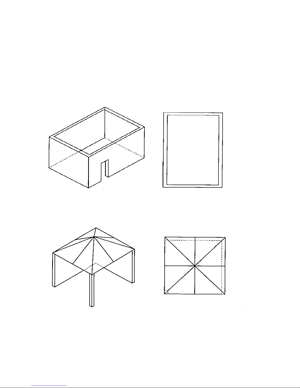
Any enclosure in which the appliance is used shall comply with one of the
following:
An enclosure with walls on all sided, but at least one permanent
opening at ground level and no overhead cover.(figure 1)
Within a partial enclosure that includes an overhead enclosure and no
more than two walls.(figure 2)
Within a partial enclosure that includes an overhead cover and more
than two walls, the following shall apply.(figure 3,4 ,5)
(a.) At least 25% of the total wall area is completely open.
(b.) At least 30% of the remaining wall area is open and unrestricted.
In the case of balconies, at least 20% of the total of the side, back and
front wall areas shall be and remain open and unrestricted.

6
DIAGRAMMATICAL REPRESENTATIONS
OF OUTDOOR AREAS
The following figures are diagrammatical representations of outdoor areas. The
areas used in the figures below are examples –the same principles apply to any
other shaped area.
BOTH ENDS OPEN.
FIGURE F1 –OUTDOOR AREA –EXAMPLE 1
FIGURE F2 –OUTDOOR AREA –EXAMPLE 2

- 7 -
FIGURE F3 –OUTDOOR AREA –EXAMPLE 3
FIGURE 4 OUTDOOR AREA –EXAMPLE 4
Both ends open
Open side at
least 25% of
total wall area
30% or more in total
of the remaining wall
area is open and
unrestricted.

8
OPEN AT SIDE AT LEAST 25% OF TOTAL WALL AREA.
30% OR MORE IN TOTAL OF THE REMAINING WALL AREA IS OPEN AND
UNRESTRICTED
OPEN SIDE AT LEAST 25% OF TOTAL WALL AREA.
30% OR MORE IN TOTAL OF THE REMAINING WALL AREA IS OPEN AND
UNRESTRICTED.
FIGURE F5 –OUTDOOR AREA –EXAMPLE 5
Open side at
least 25% of
total wall area
30% or more in total
of the remaining
wall area is open
and unrestricted.

- 9 -
GTR S AND GTR SS need new sizes
360
470
50
Hole size on bench top to fit
bottom lip of the side burner:
Width
Depth
325mm
445mm
NOTE: The optional built in or intergrated side burner gas consumption is below.
TECHNICAL DATA
The nominal gas consumption of the GTR S and GTR SS Side Burner.
Model Gas type Injector Pressure Input AGA
GTR S Propane 1mm 2.8 kpa 12mj/hr
GTR S Natural 1.6mm 1 kpa 12mj/hr
GTR SS Propane 1.2mm 2.8 kpa 18mj/hr
GTR SS Natural 1.9mm 1kpa 18mj/hr
TUCKER GTR S and GTR SS SIDE BURNERS ARE MADE AND APPROVED TO
AUSTRALIAN STANDARDS A.G.A. APPROVAL 8236 G
For LP Gas connections, an approved 2.8 KPA regulator and hose assembly must
be used.
DIMENSIONS FOR BUILDING GTR S and GTR SS
SIDE BURNER INTO BRICKWORK
INTO BRICKWORK.

10
The appliance inlet is 3/8 S.A.E. male and is located at the front underneath the side
burner.
The minimum capacity propane cylinder for this side burner is 4 KG.
The intended use of this side burner is to be installed onto a Tucker GTS or GTR Trolley
or alternatively it may be set into brickwork or the like with the following clearances to
combustibles.
Minimum Top Clearance - Allow 800mm
Minimum Side Clearance - Allow 200mm
Minimum Rear Clearance - Allow 200mm
Be sensible about the location of your side burner.
The barbecue and side burner must be located on firm and level ground.
Do not locate the barbecue or side burner near combustible materials or surfaces,
either above or around the sides.
Do not obstruct any of the air ventilation openings, under or around the sides of the side
burner.
Connection of a side burner to a BBQ and or gas cylinder is as
follows.
For the attachment of a GTR ST or GTR SST Side Burner you will need to
disconnect the hose from the BBQ and re-connect it to the right hand side of the
side burner. Then connect the shorter hose supplied with the side burner to the left
hand side of the side burner and the other end to the BBQ inlet.
The hose connections must be connected firmly with a spanner.
Check that the hose is not kinked or under tension.
Apart from the connection point the hose must not be touching any part of the
barbecue or side burner where it may get hot and be damaged.

- 11 -
Side burner inlet fitting BBQ inlet fitting
WARNING: THERE MUST BE NO NAKED FLAMES IN THE
AREA WHEN CONNECTING THE SIDE BURNER TO A
BARBECUE AND OR GAS SUPPLY.
Attachment of the gas cylinder to the regulator and hose.
Attach the regulator to the Gas Cylinder by
using the wing Nut or wheel nut fitted onto
the regulator. Note, the regulator and gas
bottle have left hand threads, there is an
arrow printed on the fitting showing the
intended way to tighten the regulator into the
gas bottle. Warning this must be tightened
firmly by hand so that it does not leak gas.

12
Once connected leak test all the connections by brushing a solution of soapy water
around the joints and the gas cylinder valve.
NOTE: You must have the control knobs in the
off position and have the gas supply turned on at
the cylinder valve so as to do this leak test.
If bubbles appear around the connections you
have a leak.
Photo of what a typical leak looks like.
If you find a leak, turn off the gas supply and tighten or re-seal the connection.
Leak test the connections again.
Photo example of a good connection
i.e. no bubbles
If leaks are still present do not use the
barbecue, contact the place of purchase or
your local dealer.
For storage, cylinder exchange or refilling, disconnect the hose at the cylinder only.
Do not disconnect the hose from the appliance. NOTE: check for leaks after each
gas refill and re-connection.
Do not attempt to open or adjust the regulator, if you think it is not working
properly consult your local dealer.
.

- 13 -
FOR PERMANENT CONNECTIONS to natural gas or a fixed propane supply, an
authorised person, in accordance with these instructions, local gas fitting
regulations, municipal building codes, the AGA installation code AS5601 and any
other relevant statutory regulations, must be employed.
For connection to a natural gas bayonet fitting, a gas regulator must be fitted at the
inlet of the appliance, and an approved 10mm, class A, natural gas hose (no longer
than 2 metres), going from the gas regulator to the bayonet point, complying with
AS1869 must be used.
It is recommended that an isolation valve and union be fitted before the barbecue
or side burner; refer AS5601/ AG601 for correct pipe sizing to ensure adequate gas
is supplied to the appliance.
For natural gas check the pressure of the regulator, and adjust if necessary to the
pressure shown on the data plate.
CONVERSION PROCEDURE
FOR AUTHORISED INSTALLER
PROPANE GAS TO NATURAL GAS CONVERSION.
Disconnect and disassemble burner.
Remove injectors and replace with the correct size injectors see the data plate or
instructions.
Re-assemble burner.
Replace the PROPANE GAS hose and regulator with an approved natural gas
regulator and hose.
Turn the gas on and test the appliance for leaks, repair if necessary.
Light the burner and set the pressure at 1 KPA.

14
Turn the burner to the “LOW” setting and adjust it if necessary by removing the
control knob and using a 2.4mm slotted screw driver you can adjust the “low”
setting up or down to suit your gas pressure.
Note: Turn screw driver anti-clockwise to adjust the flame height up, NOTE, you
want to achieve the lowest flame height at “LOW”but you don't want to have it so
low that it blows out on its own or due to a breeze.
Check the operation of the ignition to the burners and make any necessary
adjustment.
Ensure the data plate is changed / altered to contain correct information i.e.
remove the old Gas type label and replace it with a natural gas label and date of
conversion.
For alternative types of installation, contact your nearest dealer.
OPERATING INSTRUCTIONS
1. Check the burner is turned off and gas fittings are properly connected.
2. Open the lid of the side burner, the lid or roasting hood must always be open
before lighting the side burner.
3. Check that the burner is fitted correctly
The GTRS burner cap must be sitting level on top of the burner base. The
two rings must be also sitting level covering the burner ports.
The GTR SS burner is already factory fitted into the appliance.
4. Do not use if strong winds are present.
5. Do not let children operate this appliance.
6. The lid must be closed when the burner is not in use.

- 15 -
NOTE: GTR S Side burner can be used with
a pot or saucepan when the trivet wings are
down as in the picture.
The trivet wings can be turned up to cradle
a larger wok with a round bottom.
NOTE : GTR SS Side burner has 2 fixed trivets that can be removed depending on
the size of the pot or wok to be used.
NEED A PICTURE
NOTE , If using the side burner with a roasting hood fitted above it then the
roasting hood must always be open when lighting the side burner. Do not
close the roasting hood whilst the side burner is operating unless a griddle
plate is fitted above the burner.

16
LIGHTING INSTRUCTIONS
ALWAYS OPEN THE FLAT LID OR ROASTING HOOD BEFORE LIGHTING.
1. Turn on the gas supply.
2. Depress and turn the control knob to high.
3. Push the igniter button 1 to 3 times.
4. If the burner fails to light, turn the control knob off and repeat the procedure.
5. Low setting is obtained by turning the control knob to the low setting.
6. To turn off, turn the control knob to off.
7. Do not close the lid of side burner until you turn off the side burner.
Trouble Shooting
Finding it hard to light side burner? Check that the igniter is sparking, if not
check underneath that the igniter lead is plugged into both the igniter and the
probe. Check that the ignition probe is arching into the ports on the ring burner.
The burner only lights on part of the ring burner? Wipe the ports with a hot
cloth, they may have grease or food spillage on them, you may need to unblock
the ports by pushing a skewer through them or similar object to remove blockages.
No gas seems to be coming through to the burner? Check the gas supply is
turned on and there is gas in the cylinder. Check the hose is not kinked or split.
Maybe the injector is blocked and may need removing and cleaning.
The control knob will not move or it is really stiff? Remove the control knob by
lifting it up off of the control valve shaft, spray it with WD40 or Inox unceasing
lubricant leave it to soak in for a few minutes then put the knob back on and try to
turn the valve shaft free, once it starts to move freely, oil the valve shaft.

- 17 -
Maintenance and Service instructions
The lid must be closed when the burner is not in use.
Clean the side burner with warm soapy water after each use.
Have the side burner serviced by an authorized person every two years.
Periodically remove the burner tops and scrub them with warm soapy water if
exposed to harsh weather or heavy usage then cleaning will be required more often.
Make sure the burner ports and air vents are clear from obstructions. Replace the
burner and light it to evaporate any moisture from the burner after washing.
Check the flame pattern of the burner and adjust burner if necessary.
Remove the control valve knob and oil the valve shaft every 2 months.
Do not attempt to dismantle the gas control valve or the regulator.
FOR SERVICE OR REPLACEMENT PARTS, CONTACT THE NEAREST DEALER OR
TUCKER AUSTRALIA PTY. LTD.

18
TUCKER SIDE BURNER WARRANTY
WARRANTY PERIOD
Stainless steel body 10 years
Stainless Burner 2 years
Alloy burner 2 years
Enamel rings 2 year
Control valve 2 years
Ignition 1 year
All other parts 1 year
Should any part fail due to defective workmanship or faulty materials within the
specified period from the date of purchase, TUCKER distributors will repair or,
(distributors option), replace the defective part free of charge.
NOT COVERED
The warranty does not cover the purchaser or any other person for damage,
malfunction or loss due to the following:
Lack of maintenance, abuse, neglect, misuse, accident, or improper
installation of this appliance.
Scratches, dents, or discolouration caused by heat, abrasive or chemical
cleaners or chipping of enamel parts.
Damage due to grease or fat fires.
Failure of burners and valves due to insect’s nests or dirt/ dust.
Surface rust.
Commercial use of the Side Burner.
Unauthorised repairs during the warranty period.
Removal or re-installation costs.
SERVICE CALLS OF THE ABOVE NATURE ARE CHARGEABLE.

- 19 -
CONDITIONS OF THIS WARRANTY
1. The appliance is delivered to TUCKER AUSTRALIA distributer’s service
department or authorised service agent and freight charges both ways are to
be paid by the owner. No liability is accepted for loss or damage transit.
2. The appliance is to be installed by a qualified person and operated and
maintained in accordance with the instructions supplied. An authorised
person must carry out repairs and service.
3. Installation must conform to the standards laid down by the local codes or,
in the absence of local codes, with AGA code AG: 601 AS: 5601:2002
4. No alterations or repairs are to be carried out without obtaining the
distributors prior consent. Such repair or any replacement does not extend
the warranty period.
5. Proof of purchase together with this warranty must be provided to verify
purchase date and establish the warranty period. Only the original purchaser
is covered under this warranty.
6. Where this warranty is inconsistent with any state laws, the rights of the
purchaser shall prevail.
7. Parts installed from other manufacturers products will nullify this warranty.
FOR YOUR RECORDS
Model: ........................................................`............
Serial Number: .......................................................
Retailer: ..................................................................
Purchase Date: .......................................................
Gas type: ............................................……………...
TUCKER AUSTRALIA PTY LTD.
2/91 DARLEY STREET.
MONA VALE NSW 2103.
AUSTRALIA.
This manual suits for next models
2
Table of contents
Popular Burner manuals by other brands

AOG
AOG IRB-18 instructions

baltur
baltur SPARKGAS 20P - 20PW Instruction

Riello
Riello 467 T80 Installation, use and maintenance instructions

Ecoflam
Ecoflam MAX GAS 170 LN P TC SGT 230-50 TW operating instructions

Comtherm
Comtherm PP Series Installation & maintenance manual

baltur
baltur TBML 900 ME Instruction manual for installation, use and maintenance

Bentone
Bentone B 70i-3R FAME J Assembly, installation and maintenance instructions

Riello
Riello DB4 SE C03 A180 FS2 Installation, use and maintenance instructions

Deni
Deni 16310 Use and care instructions

Pelltech
Pelltech PV 20a user manual

Alfresco
Alfresco SC93MAN02 Assembly & operating manual

Maxon
Maxon INDITHERM 100 Specifications