TUFFA TANKS 30000VBFS Owner's manual

TUFFA
FUEL
STATIONS
Installation, Operation and Servicing Manual Version 3.0.0
Models:
1350SLBFS | 2500HBFS | 3500VBFS | 6000VBFS | 10000VBFS | 15000VBFS | 30000VBFS

1
1. Introduction 2
2. Conditions of use 2
3. Safety 3
4. Product description 4
4.1 Productidentication 4
4.2 Productspecication 5
4.3 Product dimensions 6
5. Transport & storage 13
6. Installation & commissioning 14
6.1 Installationguidelines 14
6.2 Systeminstallation 14
6.3 Systemlocation 14
6.4 Electricalrequirements 15
6.5 Electricalwiringdiagram 15
7. Operation of the system 17
7.1 Usingthesystem 17
7.2 Summaryofmainparts1350/1400/2500 17
7.3 Summaryofmainparts3500/6000/10000/15000/30000 19
7.4 Fillingdieselfuelstation 20
7.5 Dispensingdieselintovehicle 20
7.6 Equipmentcomponents 21
8. Maintenance of the TUFFA TANKS 44
8.1Systemmaintenancetasks 45
8.2 Inspection by competent person 45
8.3Internalexaminationandcleaning 45
8.4Troubleshooting 46
8.5Tankmaintenancerecord 52
8.6Fueldeliverylog 54
9. Warranty 56
10. Contact 57
11. Guarantee Registration 57
CONTENTS PAGE

23
3. Safety
PLEASE READ THIS MANUAL CAREFULLY BEFORE USE & COMPLY WITH ALL
INSTRUCTIONS BELOW.
THIS MANUAL SHOULD BE KEPT WITH THE EQUIPMENT AT ALL TIMES.
1.Themajorhazardinvolvedwithinstallingandoperatingtheunitiselectricalshock.
Thishazardcanbeavoidedifyouadheretotheproceduresinthismanualandexercise
allduecare.
2.Installationanduseofthisproductshouldonlybecarriedoutbyproperlytrainedand
approvedpersonnel.
3.PleaserefertostoragemediaMSDSwhichshouldbesuppliedbytheproprietorofthis
systemwhichwilldetailthePPErequiredforhandlingandemergencyprocedures.
4.Theuserofthisproductisresponsibleforthesafeandcorrectuseofthisproduct.
5.Thisproductisonlysuitableforstorageand/ordispensingoftheliquidmedia
referencedatthepointofsale.
1. Introduction
Thismanualcontainsspecicinstructionsandinformationrelatingtotheinstallation,
operationandmaintenanceofTuaTankssystems.
2. Conditions of use
• Readthismanualbeforeinstallingthissystem.
• TuaTanksacceptsnoliabilityforpersonalinjuryorpropertydamageresultingfrom
workingonoradjustingtheequipmentincorrectlyorwithoutauthorisation.
• TuaTanksacceptsnoliabilityfordirect,indirect,incidental,special,or
consequentialdamagesresultingfromfailuretofollowanywarnings,instructions,and
proceduressetoutinthismanual.
• TuaTanksreservestherighttochangethespecicationsofitsproductsorthe
informationinthismanualwithoutnecessarilynotifyingitsusers.
• VariationsininstallationandoperatingconditionsmayaecttheTuaTanksystems
performance.TuaTanksmakesnorepresentationsorwarrantiesconcerningthe
performanceofthetanksystemundertheoperatingconditionsprevailingatthe
installation.
• OnlypartssuppliedbyorapprovedbyTuaTanksmustbeusedandno
unauthorisedmodicationstothehardwareorsoftwareshouldbemade.Theuseof
non-approvedpartsormodicationswillvoidallwarrantiesandapprovalsandcould
leadtohazardoussafetyconditions.
• Unlessotherwisenoted,referencestobrandnames,productnames,ortrademarks
constitutetheintellectualpropertyoftheownerthereof.
1. INTRODUCTION | 2. CONDITIONS OF USE 3. SAFETY

45
4.2 Product specication
1350SLBFS 2500HBFS 3500VBFS 6000VBFS 10000VBFS 15000VBFS 30000VBFS
Capacity 1350litres 2500litres 3500litres 6000litres 10000litres 15000litres 30000litres
Length 2680mm 2840mm - - - - 6080mm
Width 870mm 1520mm - - - - 2890mm
Diameter - - 2013mm 2550mm 2890mm 2890mm -
Height 1665 mm 1630mm 2520mm 2585 mm 2590mm 3500mm 3500mm
Cabinet depth - - 600mm 600mm 600mm 600mm 600mm
Weight (approx.) 190kgs 280kgs 350kgs 430kgs 500kgs 700kgs 1330kgs
Bund material LowerLinearDensityPolyethylene
Inner tank
material
LowerLinearDensityPolyethylene
Description Bundeddieselfuelstation
Fill point 2” BSP 2” BSP 2”BSPwithoverllpreventionvalve
Ventilation 1x3”vents 2x3”vents
Flow rate Standardowrate-52LPM(approx.)
Highowrate-72LPM(approx.)
Flowmeter Mechanicalowmeter(accuracy+/-1%)
Delivery hose 6 metres
Hose reel
(optional)
N/A Hosereelavailable
Nozzle Automaticshutonozzle
Filtration 10micronwaterandparticulatelter
Gauge ClockGauge FMSgaugeandbundalarm(230V)
4. Product description
TuaFuelStationsaredesignedsolelyforstorageanddispensingofdiesel.Thestatic
bundedsystemsenablesafedieselstorageanddispensinginanoutdoorenvironmentand
ensuresyoumeetallstringentfuelstorageregulations.Thehighstandardofspecication
ensuresoptimumsafetyandfunctionality.Thisproduct’sstandardspecicationisnot
approvedfortheresaleofdiesel.
4.1 Product identication
Theidenticationplateislocatedwithinthecabinetofeachsystemandwilldetailthe
capacity,serialnumber,modelnumberandyearofmanufacture.
4. PRODUCT DESCRIPTION 4. PRODUCT DESCRIPTION

67
4.3 Product dimensions
1350SLBFS
1
1
2
2
3
3
4
4
5
5
6
6
A A
B B
C C
D D
1350 BUNDED
DESIGNED BY CHECKED BY APPROVED BY DATE DATE
Rob Smith J Shenton J Shenton 11/06/2020 10/06/2020
ISSUE SHEET
D1 / 1
MATERIAL
LLDPE
1665 mm
870 mm
2680 mm
4. PRODUCT DESCRIPTION
2500HBFS
1
1
2
2
3
3
4
4
5
5
6
6
A A
B B
C C
D D
2500 BUNDED
DESIGNED BY CHECKED BY APPROVED BY DATE DATE
Rob Smith J Shenton J Shenton 11/06/2020 10/06/2020
ISSUE SHEET
D1 / 1
MATERIAL
LLDPE
2840 mm
1630 mm
1520 mm
4. PRODUCT DESCRIPTION

89
6000VBFS
3500VBFS
4. PRODUCT DESCRIPTION4. PRODUCT DESCRIPTION
1
1
2
2
3
3
4
4
5
5
6
6
A A
B B
C C
D D
3500 BUNDED WITH CABINET
DESIGNED BY CHECKED BY APPROVED BY DATE DATE
Rob Smith J Shenton J Shenton 11/06/2020 10/06/2020
ISSUE SHEET
D1 / 1
MATERIAL
LLDPE
2013mm
2613 mm
1200 mm
2520 mm
2000 mm
1
1
2
2
3
3
4
4
5
5
6
6
A A
B B
C C
D D
6000 BUNDED WITH CABINET
DESIGNED BY CHECKED BY APPROVED BY DATE DATE
Rob Smith J Shenton J Shenton 21/10/2020 21/10/2020
ISSUE SHEET
E1 / 1
MATERIAL
LLDPE
2550mm
1200 mm
2000 mm
3150 mm
2585 mm

10 11
15000VBFS
1
1
2
2
3
3
4
4
5
5
6
6
A A
B B
C C
D D
15000 BUNDED WITH CABINET
DESIGNED BY CHECKED BY APPROVED BY DATE DATE
Rob Smith J Shenton J Shenton 11/06/2020 10/06/2020
ISSUE SHEET
D1 / 1
MATERIAL
LLDPE
2890mm
1200 mm
3500 mm
2000 mm
3460 mm
10000VBFS
1
1
2
2
3
3
4
4
5
5
6
6
A A
B B
C C
D D
10000 BUNDED WITH CABINET
DESIGNED BY CHECKED BY APPROVED BY DATE DATE
Rob Smith J Shenton J Shenton 11/06/2020 10/06/2020
ISSUE SHEET
D1 / 1
MATERIAL
LLDPE
2890mm
2590 mm
1200 mm
2000 mm
3490 mm
4. PRODUCT DESCRIPTION

12 13
4. PRODUCT DESCRIPTION
5. Transport & storage
DO NOT TRANSPORT WITH LIQUID INSIDE THE TANK
1. Duringtransportationtheiplidandcabinetdoorsaresecuredby1xRclip.TheR
clipmustbeinstalledpriortotransportation.
2. Loadingando-loadingmustbecarriedoutbyacompetentpersonusingsuitable
ratedandmaintainedequipment,eitheraforkliftwithextendedforks/tinesoracrane.Iflifting
slingsareused,theymustbeattachedtotheliftingpointsasshowninthepicturesbelow
usingasteelliftingeyeinsert.Ifliftingfrombelowuseasuitableratedforkliftwithextended
forks.Ifliftingfromaboveuseasuitableratingliftingslings/chains.
3. 1350SLBFS/2500HBFS-Liftwithmainliftingeyehighlightedinredintheimage
beloworforkliftfromtheside.
4. 3500VBFS/6000VBFS/10000VBFS/15000VBFS-Liftwithx4equalspacedlifting
bracketsashighlightedinredintheimagebeloworforkliftfromonesideusingaratchet
straptosecurethetanktotheforkliftmast.
5. TuaFuelStationsmustneverbepushedorrolled.
6. Duringtransportandstorage,theiplidorcabinetdoorsmustbeclosedandsecured.
7. Loading,transportandstorageareasmustbesmoothandfreeofsharpedges.
5. TRANSPORT & STORAGE
30000VBFS
A ( 1 : 10 )
A
1
1
2
2
3
3
4
4
5
5
6
6
A A
B B
C C
D D
DESIGNED BY CHECKED BY MATERIAL DATE
Rob Smith J Shenton 01/06/2020
ISSUE SHEET
B1 / 1
WEIGH
T
30000VBFS
300 mm
2890mm
3500 mm
2000 mm
600 mm
1200 mm
6020 mm

14 15
6. Installation & commissioning
6.1 Installation guidelines
TheproprietoroftheTuaFuelStationisresponsibleforcomplyingwithalllegal
requirementsrelatingtotheinstallationanduseofthisproduct,aswellastheguidelines
issuedbylocalreghtingauthoritiesandenvironmentalauthorities.
OncetheTuaFuelStationhasbeenreceivedonsite,checkthatnodamagehasoccurred
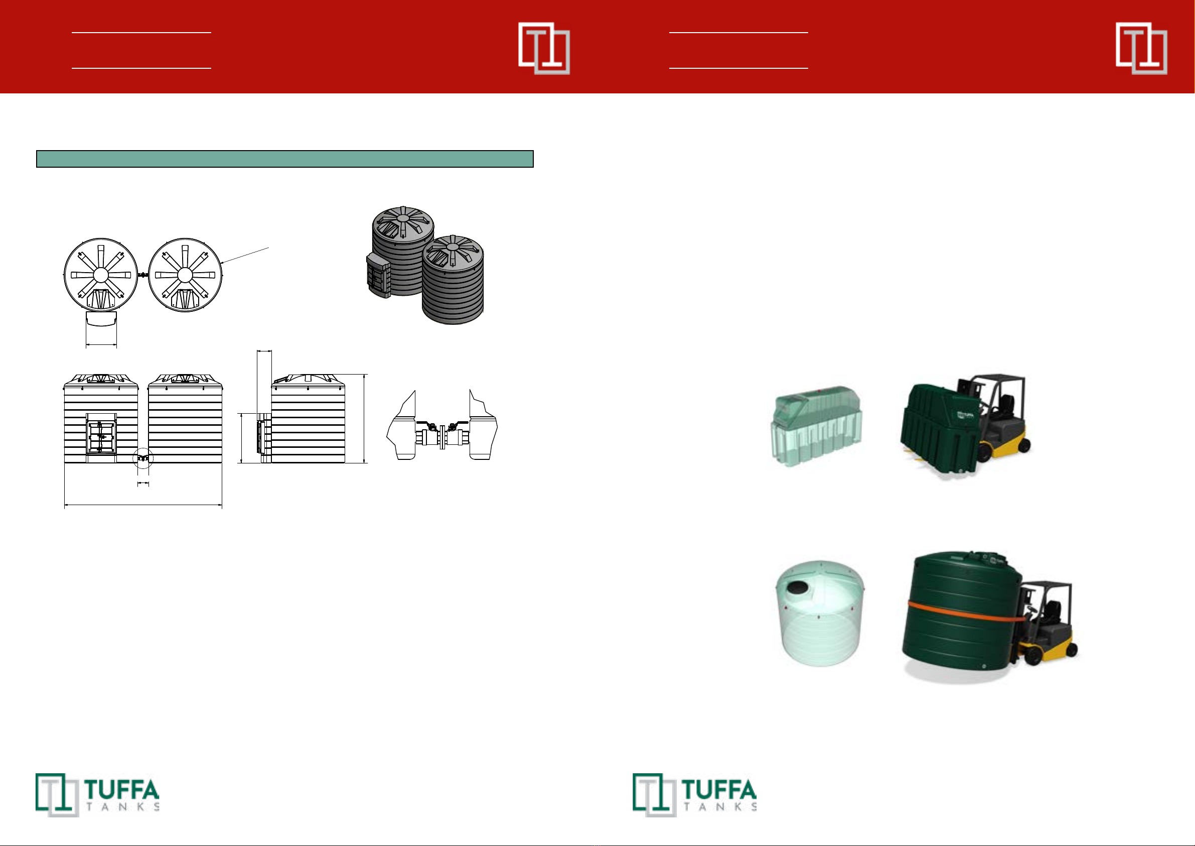
whileintransit.Locatethetankinthedesiredlocationusingeitheracrane,forkliftorrollers.
6.2 System installation
Systemfoundation
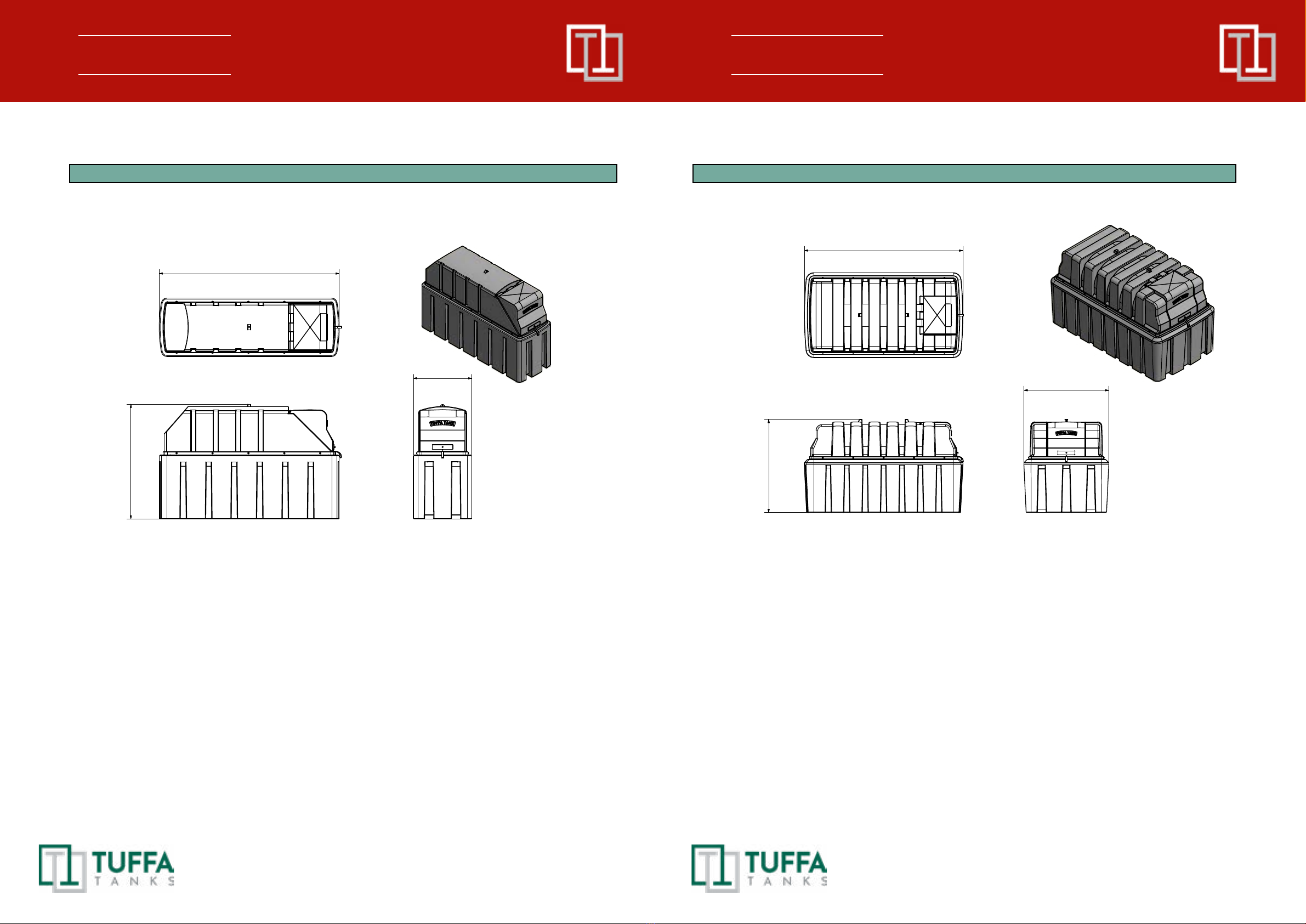
Thesystemmustbeinstalledandfullysupportedonasmoothlevelledconcretebasebuiltin
accordancewithgoodbuildingstandardsandengineeringprinciples.Itisrecommendedthat
tanksbeinstalledonaconcretebaseatleast100mmthick.Pleaserefertodiagrambelow:
6.3 System location
Thelocationofthesystemshouldbepositionedbyaroadorpassingwithsucientwidth,
andloadingcapacitytoaccommodateatankerdeliveringdiesel.ProvisionfortheU-turnof
atankershouldbeconsidered.Potentialobstaclesintheformoftreebranches,highvoltage
lines,orparkedvehiclesmustbeminimized.
Thespacearoundthesystemshouldallowfreeandcollision-freemovementofserved
vehicles.
Provisionshouldbemadetoprotecttankfromimpactdamage.
6. INSTALLATION & COMMISSIONING
6.4 Electrical requirements
Onlyasuitablyqualiedelectricianaccordingtoapplicableregulationsmayworkonthe
electricwiringinstallation.Thesystemcomponentsunderservice,maintenance,andrepair
workmustbedisconnectedfromthepowersupplybeforeanyworkinundertaken.
System power requirements:
230V
• 220-240Volts,50Hz+/-10%
• 20ampcircuitbreakerrecommended
• Powercablerecommendation:3Core2.5mmexcable
• Dutycycle:20minutes
• CAUTION: DO NOT RUN PUMP MOTOR WITH A CLOSED NOZZLE FOR MORE
THAN 2 MINUTES
12V/24V
• Cableclipscomepre-wired
• Dutycycle:20minutes
• CAUTION: DO NOT RUN PUMP MOTOR WITH A CLOSED NOZZLE FOR MORE
THAN 2 MINUTES
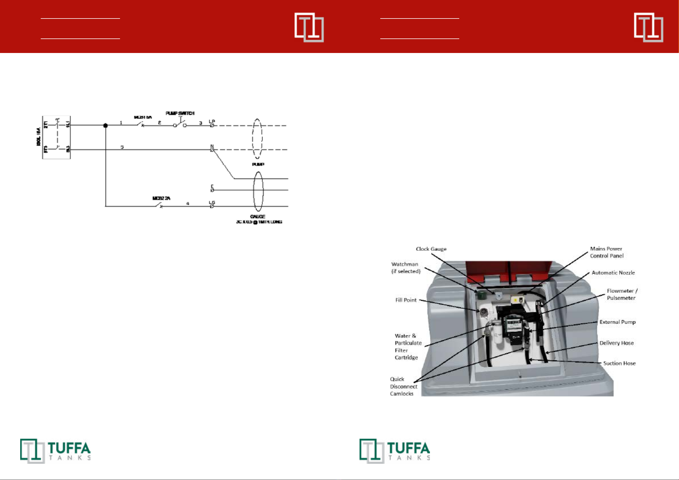
6.5 Electrical wiring diagram (230 V)
6.5.11350SLBFS/2500HBFS–KeySwitch
6. INSTALLATION & COMMISSIONING

16 17
6.5.2 3500VBFS/6000VBFS/10000VBFS/15000VBFS/30000VBFS–KeySwitch
6. INSTALLATION & COMMISSIONING
7. Operation of the system
Thesystemanditscomponentsareintendedfordieselfuelonlyandforthepurposes
describedbelow.Useofthissysteminameansotherthandescribedbelowisregardedas
mis-useofthesystem,theuserofthesystemwillbeliableforanydefectsthatoccurdueto
its unintended use.
7.1 Using the system
Theoperationandmaintenancepersonnelmustbesuitablytrainedtousethesystem,the
usermustmakesuretheyfullyunderstandtheoperationandmaintenancesectionsofthis
manual.
7.2 Summary of main parts 1350 / 2500
(230V)
7. OPERATION OF THE SYSTEM

18 19
(12V / 24V)
Clock Gauge
Water &
Particulate
Filter
Cartridge
Fill Point Mechanical
Flowmeter
Automatic Nozzle
External Pump
Quick
Disconnect
Camlocks
Delivery Hose
Suction Hose
Battery
Cable Clips
Watchman
(if selected)
7. OPERATION OF THE SYSTEM
7.3 Summary of main parts 3500 / 6000 / 10000 / 15000 / 30000
(230V)
(12V/24V)
Level Gauge &
Tank Alarm
External Pump
Mains Power
Control Panel
Water &
Particulate
Filter Cartridge
Fuel Management
System
Fill Point
Automatic Shut-Off
Nozzle
Delivery Hose
Hosereel
7. OPERATION OF THE SYSTEM
Hydrostatic Contents Gauge
External Pump
Battery Tank
Alarm
Water &
Particulate
Filter Cartridge
Mechanical
Flowmeter
Fill Point
Automatic Shut-Off
Nozzle
Delivery Hose
Quick Disconnect Camlocks
Suction Hose

20 21
7.4 Filling a Tua Fuel Station
1. Fillingshouldbeperformedonlyunderconstantsupervisionofanauthorisedperson.
2. Thistankcanonlybelledbyatankerequippedwitha2”femaleBSPcoupling.
3. On3500/6000/10000/15000modelsbeforellingthetankwithdiesel,please
checkthelevelofthetankandmakenoteofthetanklevelbeforellingandensurethe
high-levelalarmindicatorfunctionscorrectly.
4. Fittankerdeliveryhoseto2”BSPllcouplingontank.
5. Engagetankerpumpandbegintoll.Stopllingwhendesiredamounthasbeen
dispensedintotank,orwhenhigh-levelalarmsounds.
6. Duringthetankerllalwaysobservetanklevelgaugethroughoutthedurationofthe
llingprocess.Thetankerdrivermustobservethetankbeinglledatalltimesduringthis
process.
7. Oncecompletedisconnectdeliveryhosefromtankcoupling.
7.5 Dispensing diesel into vehicle
1. Resettheowmetertotalizerto0.
2. Activatepumpusingoneofthefollowing:rockerswitch/keyswitch/auto-
operationalnozzleholster/batterycableclips.
3. Removenozzlefromnozzleholsterandinsertthenozzlecompletelyintothediesel
tankllerneck.
4. Pulltriggeronthenozzletoallowdieseltoowintothevehicledieseltank.
5. Atthistimetheowmetercounterwillstartrecordingtheow,continuerefuelinguntil
thedesiredamountisreachedorwhenthevehicledieseltankisfull.
6. Whenthefueltankisfullthenozzlewillautomaticallyswitcho.
7. Releasethetriggerofthenozzleandreplacebackintotheholster.
8. Deactivatepumpwithrockerswitch/keyswitch/autooperationalnozzleholster/
removalofbatterycableclips.
7. OPERATION OF THE SYSTEM
7.6 Equipment components
1. FMS gauge level (3500 litres models and above)
TheFuelLevelMonitoringSystemisa240vcombineddigitaltanklevelindicatorandbund
andhigh-levelalarmthatisdesignedtoprovidebothvisualandaudiblealarmswhenevera
predeterminedlevelinastoragetankisreached.TheFMSgivesacontentreadoutinboth
litresandapercentage.
a. Full alarm
Activationofthisalarmindicatesthatthetankisfull.Thisalarmisshownthroughvisual
LED’sandaudiblesiren.Note:Thisaudibleandvisualalarmwillremaintriggeredfora
shortperiodoftimeafteritsounds.Theaudiblecanbemutedusingthemutebuttononthe
keypad.THEPUMPWILLCONTINUETODISPENSEINTHISALARMMODE.
b. High level alarm
Activationofthisalarmindicatesthetankhasreachedahighcapacityandcloseattention
mustbepaidtothedieselinsidethetank.ThisalarmisshownthroughvisualLED’sand
audiblesiren.Note:Thisaudibleandvisualalarmwillremaintriggeredforashortperiodof
timeafteritsounds.Theaudiblecanbemutedusingthemutebuttononthekeypad.THE
PUMPWILLCONTINUETODISPENSEINTHISALARMMODE.
7. OPERATION OF THE SYSTEM

22 23
c. Low level alarm
Activationofthisalarmindicatesthetankhasreachedalowlevel.Thisalarmisshown
throughvisualLED’sandaudiblesiren.Note:Thisaudibleandvisualalarmwillremain
triggeredforashortperiodoftimeafteritsounds.Theaudiblecanbemutedusingthemute
buttononthekeypad.THEPUMPWILLCONTINUETODISPENSEINTHISALARMMODE.
d. Empty alarm
Activationofthisalarmindicatesthetankisemptyandneedslling.Thisalarmisshown
throughvisualLED’sandaudiblesiren.Note:Thisaudibleandvisualalarmwillremain
triggeredforashortperiodoftimeafteritsounds.Theaudiblecanbemutedusingthemute
buttononthekeypad.THEPUMPWILLCONTINUETODISPENSEINTHISALARMMODE.
e. Bund alarm
Activationofthisalarmindicatesthatthereisproductinthebundcavity.Thisalarmisshown
throughvisualLED’sandaudiblesiren.Note:Thisaudibleandvisualalarmwillremain
triggeredconstantlyuntilmutedoruntiltheproductisremoved.Theaudiblecanbemuted
usingthemutebuttononthekeypad.Intheeventofthisitisadvisedthebundcavityis
checkedanddrainedassoonaspracticable.
f. FMS Wiring diagram
7. OPERATION OF THE SYSTEM
2. Flowmeter (tted to all systems)
1.1 GENERAL INFORMATION
TheK33meterisamechanicalowmeterwithnutatingdisk,designedtoallowaprecise
measurementofDieseloilorotheruidscompatiblewiththemanufacturingmaterial.The
nutatingdiskofthemeteringchamber(seediagram1,drawing“15”),whichissetinmotion
bytheuiditself,drivesthegeartrainlocatedinthecoverofthemeterbody(drawing“8”)
whichtransmitsthemotiontothemeter(pos.“6”).Themeterisequippedwithanon-
resettablelitretotaliserandabatchregisterwhichcanberesetbymeansofaknob(Pos.“2”)
whoseunitdigitisprovidedwithmarksforthereadoutofthetenthsofalitre.
To ensure a proper and safe use of the meter it is necessary to read and follow the instructions and warnings
contained in this manual. An improper installation or use of the meter may cause damage to objects and people.
1.2 TECHNICAL DATA
MeterMechanism Nutatingdisk
FlowRate (range) 20-120litres/min
Operatingpressure (max) 3.5bar
Burst pressure (min) 28bar
Storagetemperature (range) -20+80°C
Storagehumidity (max) 95%RU
Operatingtemperature (range) -10+60°C
7. OPERATION OF THE SYSTEM

24 25
Pressurelosswithdieseloil Flowrate(l/min) 306090
Pressureloss(bar) 0.0050.20.4
Accuracyaftercalibration +/-1%
Repeatability (typical) +/-0.3%
Batchtotalreadout 3digitsheight18mm
Totaliserreadout 6digitsheight6mm
Readoutresolution 0.1litri
Connections (inlet/outlet) 1” BSP
Weight (approximate) 1.8Kg
Packagedimensions 185x185x170mm
Optionalfeatures RegistrationinUSgallonsfemale
threadedinlet/outlet1”NPT
1.3 INSTALLATION
TheK33canbeinstalledinanyposition,onrigidpipelines
orexiblehoses,directlyonpumpsortanks.Themeter
owdirectionisxedandindicatedbyanarrow.The
meterissuppliedinthestandardconguration(A).
Themeterandthecovercanberotatedby90°to90°
inrespecttothebodyinordertocarryoutthedierent
congurationsshown(B,C,D).Theresetknobcanbe
installedeitherontherightsideorontheleftsideof
themeter.Inordertomodifythestandardconguration
followtheinstructionsgiveninsection“Disassembling
/Reassembling”.Themeterbodyisequippedwith4
blindholeswhichcanbethreaded(M5)forapossible
fastening.Ifsolidparticlesenterthemeasuringchamber
thecorrectworkingofthenutatingdiskmaybeaected.
Alwaysltertheuidbyinstallingalteronthemeterinlet
(recommendedlter400µ).
1.4 CALIBRATION
TheK33ispre-calibratedinfactorytobeusedwithDieseloil.Asspecicoperatingconditions
(suchasrealowrate,natureandtemperatureofthemeasureduid)mayaectthemeter
accuracy,are-calibrationshouldbecarriedoutaftertheinstallationhasbeencompleted.A
newcalibrationisnecessaryeachtimethemeterisdisassembledformaintenanceoperations
orwhenitisusedtomeasureuidsthatdierfromDieseloil.
1.4 CALIBRATION PROCEDURE
1.Unscrewtheplug(seediagram1,pos.“14”).
7. OPERATION OF THE SYSTEM
2.Purgethesystem(pump,pipelines,meter)ofairbydispensinguntiltheowstreamisfull
andsteady.
3.Stoptheowbyshuttingothenozzle,butletthepumprunning.
4.Resetthebatchregisterbymeansoftheresetknob(pos.“2”).
5.Dispenseattheowratewhichthebestaccuracyisrequiredat,byusingacalibration
containerhavingacapacitynotlowerthan20litres.Donotreducetheowinordertoreach
thegraduatedzoneofthecalibrationcontainer.Therightmethodistostartandstopthefull
owrepeatedlyuntiltherequiredllingisobtained.
6.Comparetheindicationofthecalibrationcontainer(realvalue)withtheoneofthemeter
(indicatedvalue).
-Iftheindicatedvalueishigherthantherealvalue,loosenthescrew(pos.“12”);
-Iftheindicatedvalueislowerthantherealvalue,tightenthescrew(pos.“12”).
7.Repeattheoperations4to6untilaccuracyissatisfactory.
8.Tightentheplug(pos.“14”)again.TheOringwhichthecalibrationscrewisprovidedwith,
hasthefunctiontoavoidaccidentallooseningoftheadjustmentscrewbutdoesnothaveany
sealingfunctions.Thereforeitisalwaysnecessarytoproperlyxtheplugwiththesealing
gasket(pos.“12”).
1.5 USE
AfterinstallationandcalibrationtheK33isreadytowork.Turntheresetknob(seediagram
1,pos.“12”)(clockwiseifitismountedontheleftofthemeterandanticlockwiseifitismounted
ontheright)untilthebatchregisteriscompletelyreset.Thetotalisercannotberesetinany
way.Makesurethatduringusepressuredoesnotexceedthevalueindicatedinsection
“Technicaldata”.
1.6 USE BY GRAVITY
K33canalsobeusedinfuelunitswhicharenotequippedwithpumpsandwheretheowis
generatedbythedierenceinfuellevelbetweenthetankandthenozzleoutlet.Asareference,
asystemcomposedofatankotheground,withthemeterinstalledrightatthebottomofthe
tank,a3-mlong1’’exiblepipeandamanualnozzletypeSelf2000,guaranteesaowrate
ofapproximately30litres/minuteifthedierenceinlevelishigherthan1.5metres.Longer
pipesornozzlesproducinghigherpressurelossesreducetheowinrespecttotheexisting
dierenceinlevel.Usebygravityisnotrecommendedwithdierencesinlevellowerthan1
metre,astheconsequentreducedowratecausesthemetertoworkoutsideitsguaranteed
accuracyrange.Oneldcalibrationisalwaysadvisableincaseofgravityinstallations.
1.6 MAINTENANCE
NoordinarymaintenanceisrequiredprovidedthatthemeterK33isproperlyinstalledand
used.Anincorrectlteringonthemeterinletmayblockorwearoutthemeasuringchamber,
thusaectingthemeteraccuracy.Shouldthisproblemoccur(seesection“Problem,Causes
andSolutions”)disassemblethemeasuringchamber,asshowninsection“Disassembling/
Reassembling”.
7. OPERATION OF THE SYSTEM

26 27
7. OPERATION OF THE SYSTEM
WARNING:
Before disassembling alwaysmake sure that all uid is drained from the meter and pipes connected to it.
Necessarycleaningcanbecarriedoutbymeansofasoftbrushorsmalltool(i.e.ascrewdriver).
Duringcleaningbecarefulnottodamagethechamberorthedisk.Carefullycheckthemeterand
replacethepartswhichhavesueredanypossibledamage.Onlyusetheoriginalsparepartkits
shownindiagram1“Explodedviewandsparepartlist”.Anewcalibrationisalwaysnecessary
aftercleaningorreplacingthemeterparts.3)Themeterresetsthepresenttotalalready.
1.7DISASSEMBLINGREASSEMBLING
K33canbeeasilydisassembledintoitsmainpartswithoutremovingthebodyfromthepipes.
1.8METERUNIT
Todisassemblethemeterunitoperateasfollows:
a.Removetheresetknobbyrmlypullingitaxially.
b.Loosenthe4retainingscrews(seediagram1,pos.“7”).
c.Loosenthe2screws(pos.“5”).
Toreassembletheunitreversetheproceduredescribedabove.
1.9RESETKNOB
Tomodifytheresetknobposition:
a.Performonlytheoperationsa)andb)describedabove.
b.Takeouttheplug(seediagram1,pos.“4”)bypushingitfromtheinsidetowardstheoutsideof
thecover.
c.Fixagaintheplugontheoppositeholebyplacingitinsidethecoverandpushingitoutwards.
d.Fixagainthemetercoverandresetknob.
1.10MEASURINGCHAMBER
Toenterthemeasuringchamberoperateasfollows:
a.Disassemblethemeterunit.
b.Loosentheeightscrews(seediagram1,pos.“7”).
c.Removethebodycover(pos.“8”)togetherwiththegearunit.Duringthisoperationbecareful
nottodamagethegasket(pos.“10”).
d.Removethewholemeasuringchamber(pos.“11”)byliftingitfromthemeterbodyandatthe
sametimepullingitbacktowardstheinletinordertoremovetheOring(pos.“16”)fromitsseat
attheoutlet.Tochecktheinsideofthemeasuringchamber(pos.“15”),removetheOringand
dividethetwohalfchamberscontainingthenutatingdisk.Measuringchamber.
Toenterthemeasuringchamberoperateasfollows:
a.Disassemblethemeterunit.
7. OPERATION OF THE SYSTEM
b.Loosentheeightscrews(seediagram1,pos.“7”).
c.Removethebodycover(pos.“8”)togetherwiththegearunit.Duringthisoperationbecareful
nottodamagethegasket(pos.“10”).
d.Removethewholemeasuringchamber(pos.“11”)byliftingitfromthemeterbodyandatthe
sametimepullingitbacktowardstheinletinordertoremovetheOring(pos.“16”)fromitsseat
attheoutlet.Tochecktheinsideofthemeasuringchamber(pos.“15”),removetheOringand
dividethetwohalfchamberscontainingthenutatingdisk.
1.11GEARUNIT
Toreachthegearunitcomponents:
a.Removethecover.
b.Loosenthescrews.
c.Removetheplate.Nowallgearscanbereachedforinspection.Shouldthegasketbereplaced,
removethebevelgearfromtheshaftbypullingaxially,thenremovethegeartogetherwith
theshaft.Thegasketreplacementalwaysrequiresthereplacementofthebushprovidedwith
thesparepartkit.Toreassemblereversetheabovedescribedprocedurepayingparticular
attentionto:
•LubricatetheOringbeforeinstallation.
•Checkthatthegearunitcanrotatefreelybeforexingthecover
1.12PROBLEMS,CAUSESANDSOLUTIONS
Problem Possible cause Corrective action
Leakfromthe
shaftgasket
-Damagedgasket Remove(seesection“Gearunit”)
andreplacetheOringandthebush
Insucient
accuracy
-Wrongcalibration Repeatcalibrationfollowingtheinstructions
insection“Measuringchamber”
-Soiledorblockedmeasuringchamber Cleanthemeasuringchamberfollowingthe
instructionsinsection“Meterunit”
-Airintheuid Locateandeliminateleaksininletlines
Reducedowrate -Cloggedorblockedmeasuringchamber Cleanthemeasuringchamberfollowingthe
instructionsinsection“Measuringchamber”
-Blockedorsoiledlter Cleanthelter

28 29
7. OPERATION OF THE SYSTEM 7. OPERATION OF THE SYSTEM
3. MC Box Fuel Management Operation
MCBOXElectronicPanelsaredesignedfortheprivatedistributionoffuel(orotherliquids).
AllofthemodelsintheseriesarecharacterisedbythesameformforwhichtheMCBOXis
known:asolidmetalstructure,high-accuracymeasurementsinthedispensedproductandPC
softwarethatisdesignedforsimplicity.
Thiselectronicpanelallowsyoutocontrolandmonitorprivateusefuelconsumptionviaafuel
dispenserwithpumpandowmeter.
TheMCsystemconsistsofamulti-userpanel,dedicatedsoftwareandtheoptiontoconnecttoa
PC
The MC BOX System has the ability to:
•Switchthepumpon;
•Recogniseauthorisedusers;
•Presetthedispensequantity;
•Managethepulsemeter;
•Manageanexternallevelswitchthatturnsothepumpintheeventofminimumowlevel;
•Operateanexternalnozzleswitch;
•ConnectdirectlytoaPC;
•Connecttoanexternalprinter
Thepaneliseasytoinstallandisadequatelyprotected.Thewiringconnectionscanbeeasily
accessed.Thegroupcanalsobesuppliedwithameter,tobeinstalledtogetherwiththepump.
Specications
Panelwithdualdisplay,keyboardandi-buttonreader.
Theelectricboxcanbeopened,allowingeasyaccesstothewiring.
Maximumpowersupply:6.5amps.
Optional
•PCSoftwarewithdedicatedRSconverterori-buttonreadertoexportdata.
•I-buttonkeysforusers.
•High-accuracyovalgearowmeters.
Performance
•80or120-usercapacity(dependingonmodel),managedviapasswordori-buttonkey.
•Totalconsumptioncalculationfordenedperiodsforeachuser.
•Localmemorythatcanstoredatauntilthelast255dispenses.
•Vehicleidenticationandmileagetrackingoption.
•Dispensingdateandtimecontrol.
•Dedicatedsoftwarethatallowsyoutoprintdispensedataforeachuser.
•Abilitytomanageupto16controlpanelswithonesinglesoftware.
•KeyreaderwithUSBplugforexportingdata.
•RSconverterwithUSBplugfordirectconnectiontothePCviacable(upto1000m)
MC Box Installation
General
TheMCBOXcanbeinstalledoutdoors.Nevertheless,itisadvisabletolocateitundertheshelter
ofarooftoensurethedispenser’slongevityandprovidegreatercomfortduringrefuelinginthe
eventofbadweather.Theinstallationofthedispensermustbecarriedoutbyskilledpersonnel
andperformedaccordingtotheinstructionsprovidedinthischapter.
Electrical connections
Thepowerconnectionsmustbeworkmanlikeperformedbyskilledpersonnel,instrictcompliance
withthelawsapplicableinthecountryofinstallationandwiththeinstructionsonthewiring
diagramsinthismanual.

30 31
7. OPERATION OF THE SYSTEM 7. OPERATION OF THE SYSTEM
TheMCBOXisequippedwith3junctionboxes.Thesecaneasilybeaccessedbyopeningthe
doortowherethescrewterminalsfortheexternalcableconnectionsarelocated.
Theconnectionsthatneedtobemadevaryaccordingtothemodel(ACorDC):
AC Versions:
Inputs Outputs Note
ACmainssupply ACmotorpowerthesame
voltageasthemains-
Voltage:230Vacor110Vac,
dependingonthemaximum
powerofthepluggablemotors:
•230Vacversion
=1400W
•110Vacversion
=750W
Nozzlecontact:
cleancontact:Openwith
nozzlereplacedandClosed
whennozzledispensing
Levelcontact:
cleancontact:Openwith
nozzleinnormalconditions
andClosedbelowthe
minimumowlevel
Pulsemeterinput:
cleancontactorOpen
Collectoroutputsignal,with60
Hzmaximumfrequencyand
between20%and80%duty
cycle
TheRS485datalinetothePC
(optional)
WARNING
Beforeaccessingtheelectricalparts,besurethatyouhavedisconnectedallofthegeneral
switchesthatpowerothedevice.
DC Versions:
Inputs Outputs Note
DCPowerSupply DCmotorpoweristhe
sameasthesupply
voltage
Voltage:12Vdcor
24Vac,dependingonthe
maximumpowerofthe
pluggablemotors:
•12Vdcversion
=600W
•24Vdcversion
=600W
PowerinputWITHIGNITIONON.
GiventheDCsystems’highpower
absorption,themotorshouldbe
poweredwhilethebatteryisbeing
recharged
Byremovingajumperand
insertingthe“inignition”
contactinitsplace,
theelectronicscanbe
poweredonlywhenthe
vehicleis
switchedon
Nozzlecontact:
cleancontact:Openwithnozzle
replacedandClosedwhennozzle
dispensing
Levelcontact:
cleancontact:Openwithnozzlein
normalconditionsandClosedbelow
theminimumowlevel
Pulsemeterinput:
cleancontactorOpenCollector
outputsignal,with60Hzmaximum
frequencyandbetween20%and
80%dutycycle
TheRS485datalineto
thePC(optional)

32 33
7. OPERATION OF THE SYSTEM 7. OPERATION OF THE SYSTEM

34 35
7. OPERATION OF THE SYSTEM 7. OPERATION OF THE SYSTEM
Commissioning
TocorrectlycommissiontheMCBOXthesequenceofoperationsindicatedbelowmustbe
followedandtheMCcontrolsystemfunctionsmustbeknown.
Electrical power supply
Oncethepowerconnectionshavebeenmade,theMCBOXcanbeenergisedbymeansofthe
masterswitchtobettedbytheinstallerontheupstreamline.SwitchingonoftheMCsystemwill
beindicatedbythelightingupofthetwobacklitLCDsttedonthefront.
NOTE:
Intheeventofcontinuouscurrentpowersupply(DC),afusesizethatisappropriatetotheDC
motor’sabsorptionlevelshouldbeintroducedtothemotorpowerline.
Forexample:
•Iftheconnectedmotorisonethatabsorbs10Amaxthena
12Adelayfuseshouldbeinserted.
•If,however,themotorabsorbs50Amax,thena60Adelay
fuseshouldbeinserted.
•Ifthefuseissmall,itcanbettedalongthecableinsidethe
junctionbox,inposition(1)(seeillustration)
•If,however,thefuseisverybig(e.g.60A)andcannot
physicallytinsidethebox,thenitcanbeinsertedalongthe
motor’spowersupplycableinposition(2)(seeillustration)
Station conguration
EveryMCBOXstationcanbeadaptedtothespecicrequirementsofthestationmanager.Todo
thistheMCcontrolsystemmustbeCONFIGURED.
WARNING
MCcongurationiscrucialandmustbedonebyskilledpersonnel.
Toperformthisoperation,theMCmanualmustbecarefullyandthoroughlyread.
Aftercompletingconguration,userPINCODEScanbeassignedtothepersonschargedwith
usingMCBOX,inaccordancewiththedetailedinformationintheMCmanual.

36 37
7. OPERATION OF THE SYSTEM 7. OPERATION OF THE SYSTEM
Disengaging the “MC” system
AlltheMCBOXfunctionsarecontrolledbytheMCcontrolsystem.
TheMCsystemcanneverthelessbedisengagedforanystartupormaintenanceactivities
requiringrepeatedpumpstarting.
Inthesecase,itisoftenconvenienttosimplifypumpstartupbynothavingtoenteranycodeand
recordanydispensingdata.
Todothis,aJUMPERhasbeenttedonthecardthatpermitsswitchingfromAUTOMATICmode
(coderequesttoaccessdispensing)toMANUALmode(nocoderequest).
In MANUALmode:
•TheMC’sLCDmaybeswitchedo(onlythebacklightis
clearlyvisible)oryoumaycontinuetoseetheindicationthat
waspresentatthetimeoftransitionfromAUTOtoMAN.
•NoPINCODEisrequiredtoactivatethepump;thepump
startswhenthedispensernozzleisremovedfromitslodging
andstopswhenitisputback(naturallythisisintheevent
thatthe“nozzlecontact”functionisused).
•Theamountdispensedisnotshowninanyway.
WARNING
Before accessing the electrical parts, be sure that you have disconnected all of
the general switches that power the device.
WARNING
Thejumperisonlyaccessiblebyopeningthefrontpanelandispositionedasshowninthe
photo.Inthisoperatingmode,MCdoesnotrecordanydatarelatingtoperformeddispensing
operations.Before accessing this jumper, the voltage must be removed.
Meter calibration
BeforeusingtheMCBOXstation,checktheMETERACCURACY.
Forthispurpose,proceedasfollows:
•EnterapreviouslyenabledUSERPINcode;
•Runthefuelintoacalibratedcontainer;
•Comparethequantityofdispenseddieselfuelusingacalibratedcontainer.
IfaccuracyisNOTsatisfactory,proceedtoCALIBRATETHEMETERaccordingtothe
instructionsinthespecicmanual.
Every day use
ThankstotheMCcontrolsystem,alltheMCBOXmodelsprovideaccesstoauthorisedusersonly.
MCacknowledgesUserauthorisationbymeansoftwoalternativesystems:
•Theenteringofa4-gureSECRETCODE(PINCODE)
•Thettingofanelectronickey(OPTIONAL)
WARNING
To correctly check accuracy, always keep to the following instructions:
• Use a precision sample container, featuring a graduated scale, with a capacity of at
least 20 litres.
• Before making the check, always make sure you have eliminated all the air from the
system and then run the fuel until a full and regular ow is achieved.
• Dispense continuously at MC BOX maximum ow rate.
• Stop the ow by quickly closing the nozzle.
• Reach the graduated area of the sample container, avoiding prolonged dispensing
at low ow rate, but rather performing short dispensing operations at maximum ow
rate.
• Compare the reading provided by the container, with that provided by MC BOX, after
waiting for all the froth to disappear
WARNING
Dierences of up to 1/10 of a litre aecting the dispensing of 20 litres of uid fall
within the guaranteed precision of +/- 0,5%.
WARNING
All the users to whom a PIN CODE is assigned must be adequately instructed and
be at least acquainted with the contents of this chapter.
This manual suits for next models
6
Table of contents
Popular Industrial Equipment manuals by other brands

Sumitomo Drive Technologies
Sumitomo Drive Technologies PARAMAX SFC Series quick start guide

Flowserve
Flowserve Limitorque HBC Series User instructions

NSK
NSK NS Series Assembly and installation

hager
hager tehalit.FWK Plus Mounting instructions

Hubbell
Hubbell GFP20FWM installation instructions

ABB
ABB GOE Series Installation and commissioning guide