OPERATIONS MANUAL
TUNPIPEB13/250
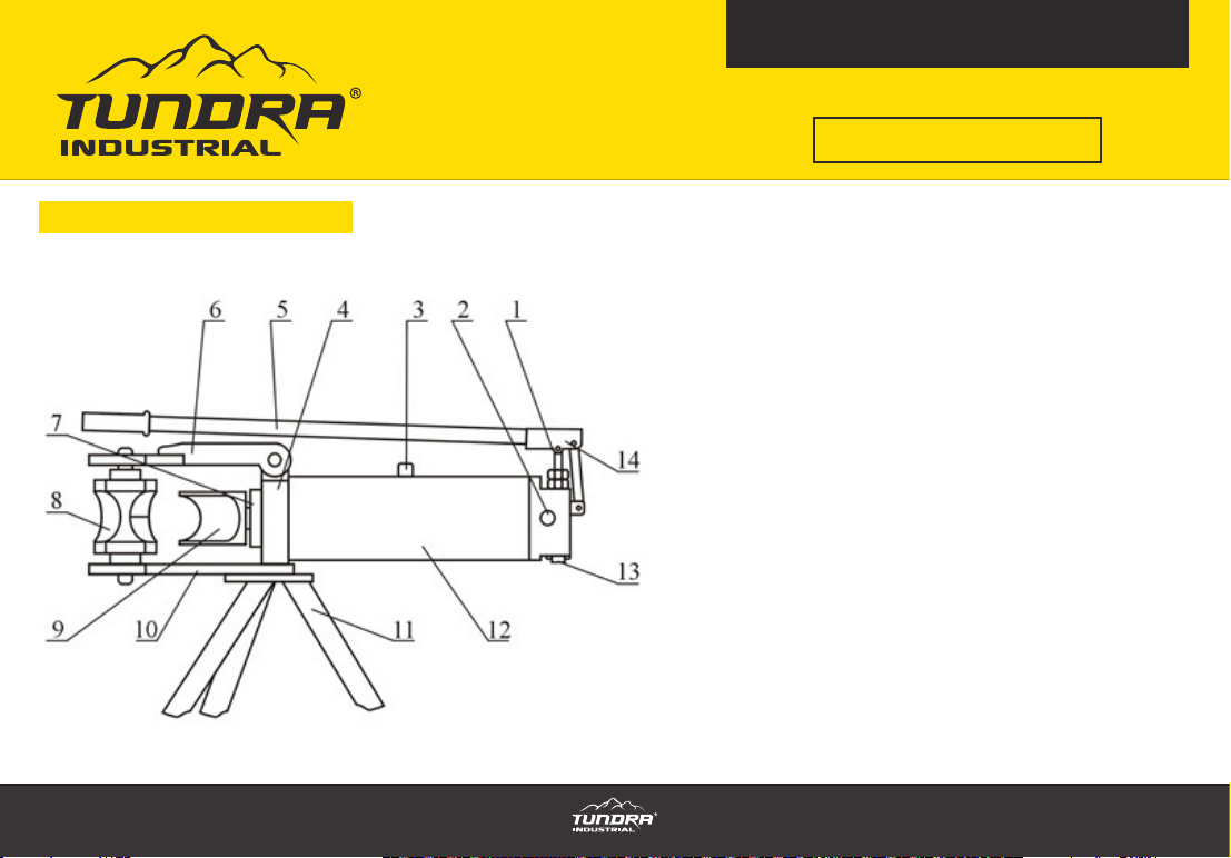
13 TONNE HYDRAULIC PIPE BENDER
5
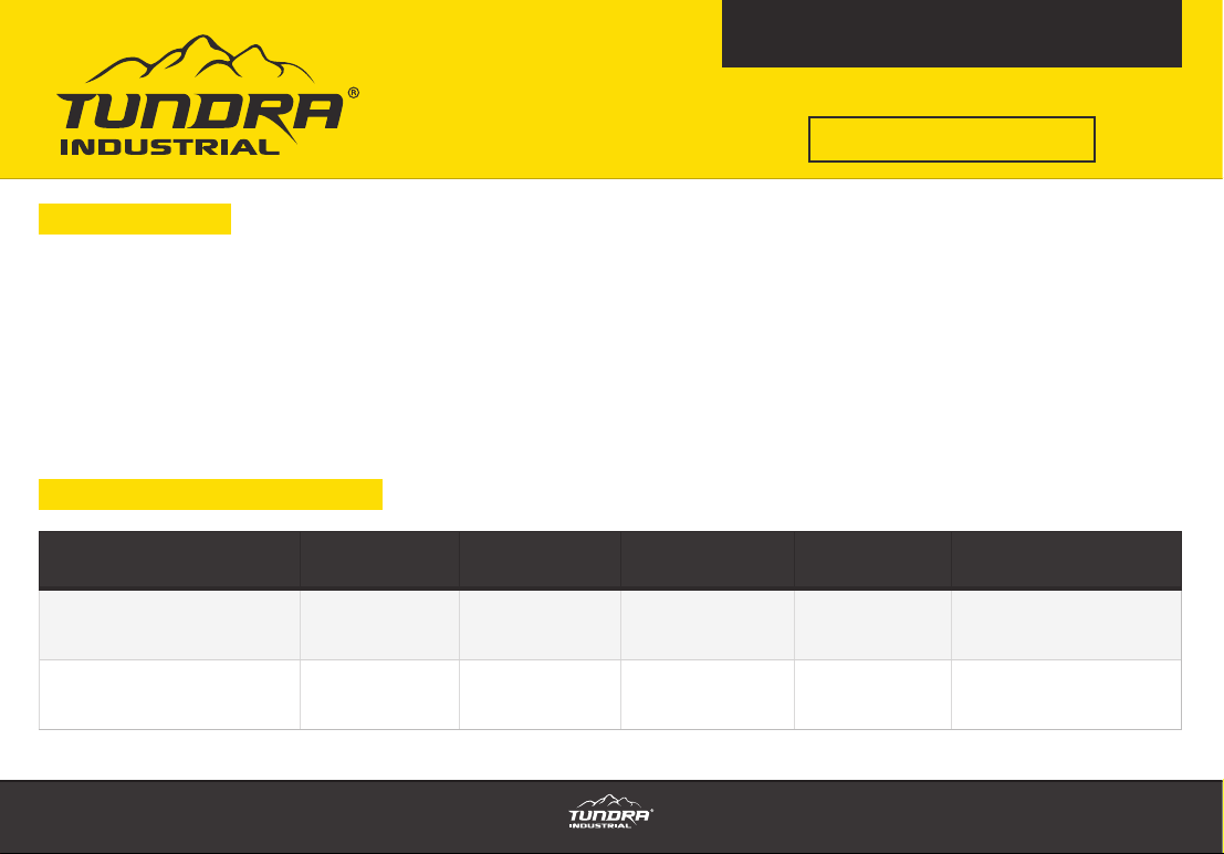
1. Spare parts have been included with this product. They are seal rings Model Y X: D28 (1Pcs) and d16 (2Pcs).
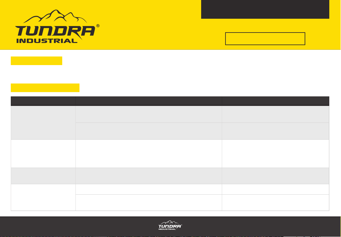
5. Spare parts
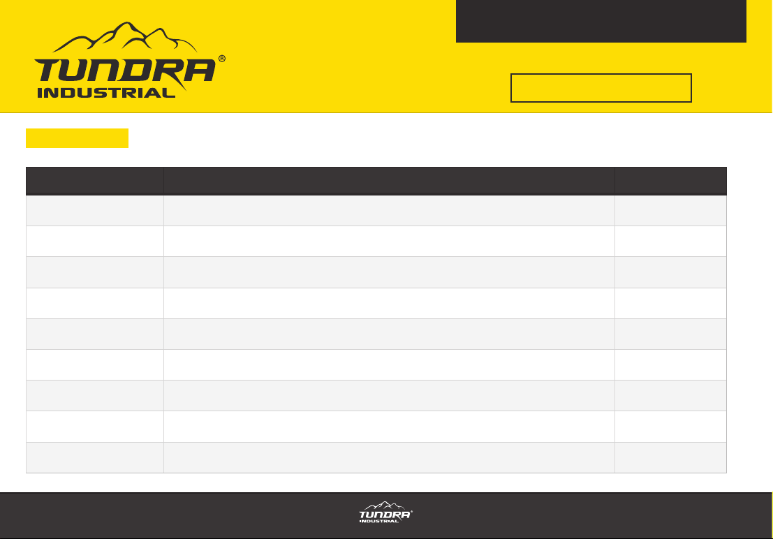
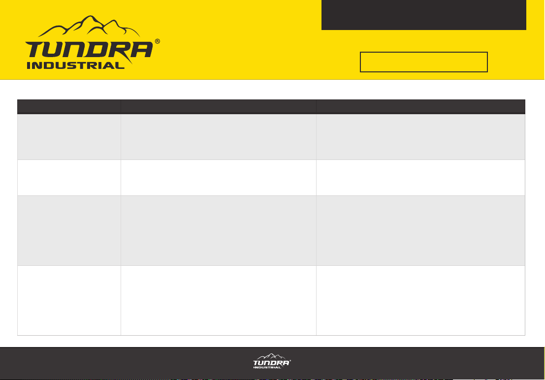
6. Troubleshooting
TROUBLE CAUSES SOLUTIONS
The pushing rod moves
unsteadily after the
piston has extended with
using the handle
The screw of oil nozzle has not been loosened Loosen the screw of the oil nozzle
The oil outlet valve on the pump is not sealed correctly or the
steel ball of the oil outlet valve is not round and smooth
Oil is dirty. Clean the oil and change the steel
ball.
The oil leaks at the ends
of the piston stems of
both large and small
pumps
The seal rings are damaged Replace them with the spare parts in the
bags supplied
Oil leakage at the pump The inner pressure ring has been loosened After dismantling the limit screw and the
valve tighten the pressure ring
Pushing force of the stem
is low
Incorrect sealing of the steel ball within the valve Change the steel ball
The steel ball has not been clamped tightly on the . Tighten the valve or if no steel ball exists
add a steel ball to the .