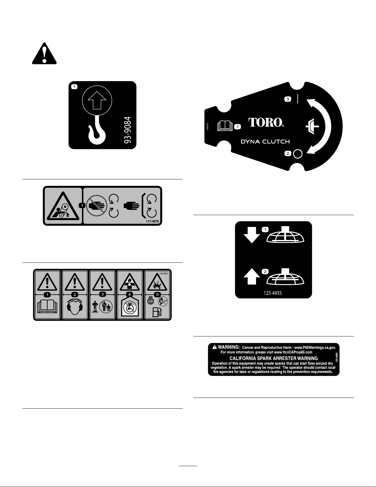
Toro PT-36PP User manual

FormNo.3429-787RevA
PT-36,PT-36PP ,PT-46,and
PT-46PPPowerTrowels
ModelNo.68048—SerialNo.404320000andUp
ModelNo.68049—SerialNo.404320000andUp
ModelNo.68050—SerialNo.404320000andUp
ModelNo.68051—SerialNo.404320000andUp
Registeratwww.Toro.com.
OriginalInstructions(EN)*3429-787*A

ItisaviolationofCaliforniaPublicResourceCode
Section4442touseoroperatetheengineonany
forest-covered,brush-covered,orgrass-covered
landwithoutasparkarrestermufermaintainedin
workingorder,ortheengineconstricted,equipped,
andmaintainedforthepreventionofre.Otherstates
orfederalareasmayhavesimilarlaws.GenuineT oro
sparkarrestersareapprovedbytheUSDAForestry
Service.
Becauseinsomeareastherearelocal,state,or
federalregulationsrequiringthatasparkarresterbe
usedontheengineofthismachine,asparkarresteris
availableasanoption.Ifyourequireasparkarrester,
contactyourAuthorizedServiceDealer.
Theenclosedengineowner'smanualissupplied
forinformationregardingtheUSEnvironmental
ProtectionAgency(EPA)andtheCaliforniaEmission
ControlRegulationofemissionsystems,maintenance,
andwarranty.Replacementsmaybeorderedthrough
theenginemanufacturer.
WARNING
CALIFORNIA
Proposition65Warning
Theengineexhaustfromthisproduct
containschemicalsknowntotheStateof
Californiatocausecancer,birthdefects,
orotherreproductiveharm.
Useofthisproductmaycauseexposure
tochemicalsknowntotheStateof
Californiatocausecancer,birthdefects,
orotherreproductiveharm.
Introduction
Thismachineisusedtocreateasmoothnishto
concreteslabs.
Readthisinformationcarefullytolearnhowtooperate
andmaintainyourproductproperlyandtoavoid
injuryandproductdamage.Youareresponsiblefor
operatingtheproductproperlyandsafely.
YoumaycontactT orodirectlyatwww.Toro.comfor
productandaccessoryinformation,helpndinga
dealer,ortoregisteryourproduct.
Wheneveryouneedservice,genuineToroparts,or
additionalinformation,contactanAuthorizedService
DealerorT oroCustomerServiceandhavethemodel
andserialnumbersofyourproductready.Figure
1illustratesthelocationofthemodelandserial
numbersontheproduct.Writethenumbersinthe
spaceprovided.
Important:Withyourmobiledevice,youcan
scantheQRcodeontheserialnumberdecal(if
equipped)toaccesswarranty,parts,andother
productinformation.
g239848
Figure1
1.Locationofthemodelandserialnumbers
ModelNo.
SerialNo.
©2018—TheToro®Company
8111LyndaleAvenueSouth
Bloomington,MN554202
Contactusatwww.Toro.com.
PrintedintheUSA
AllRightsReserved

Thismanualidentiespotentialhazardsandhas
safetymessagesidentiedbythesafetyalertsymbol
(Figure2),whichsignalsahazardthatmaycause
seriousinjuryordeathifyoudonotfollowthe
recommendedprecautions.
g000502
Figure2
1.Safety-alertsymbol
Thismanualuses2wordstohighlightinformation.
Importantcallsattentiontospecialmechanical
informationandNoteemphasizesgeneralinformation
worthyofspecialattention.
Contents
Safety.......................................................................4
SafeOperatingPractices....................................4
SafetyandInstructionalDecals..........................6
ProductOverview.....................................................7
Controls.............................................................7
Specications....................................................9
Attachments/Accessories...................................9
Operation..................................................................9
CheckingtheEngine-OilLevel............................9
CheckingtheGearcaseOilLevel......................10
CleaningDebrisfromtheMachine....................10
FoldingandUnfoldingtheHandle.....................10
AddingFuel.......................................................11
StartingtheEngine...........................................13
ShuttingOfftheEngine.....................................13
OperatingtheMachine.....................................13
Maintenance...........................................................14
RecommendedMaintenanceSchedule(s)...........14
Pre-MaintenanceProcedures..............................14
DisconnectingtheSpark-PlugWire..................14
Lubrication..........................................................15
LubricatingtheBladeArms...............................15
EngineMaintenance...........................................15
ServicingtheAirCleaner..................................15
ServicingtheEngineOil....................................16
ServicingtheGearcaseOil...............................17
ServicingtheSparkPlug...................................18
BeltMaintenance................................................19
CheckingtheBelt,PulleyAlignment,Belt
Tension,andBelt-GuideGap........................19
RemovingtheBeltGuard..................................19
InstallingtheBeltGuard....................................19
RemovingtheBelt............................................20
InstallingtheBelt..............................................20
AligningthePulleys..........................................20
AdjustingtheDyna-Clutch................................20
AdjustingtheBeltGuide...................................21
ControlsSystemMaintenance.............................22
AdjustingtheTiltKnob......................................22
AdjustingtheProPitchLinkageRod..................22
TestingtheDyna-ClutchLever..........................23
AdjustingtheBlades.........................................23
AdjustingtheBladeArms..................................25
Storage...................................................................25
Troubleshooting......................................................26
3

Safety
Improperuseormaintenancebytheoperatororowner
canresultininjury.T oreducethepotentialforinjury,
complywiththesesafetyinstructionsandalwayspay
attentiontothesafetyalertsymbol,whichmeans
Caution,Warning,orDanger—personalsafety
instruction.Failuretocomplywiththeinstructionmay
resultinpersonalinjuryordeath.
SafeOperatingPractices
Thisproductiscapableofcausingseriousinjury.
Alwaysfollowallsafetyinstructionstoavoidserious
injuryordeath.
WARNING
Engineexhaustcontainscarbonmonoxide,
anodorless,deadlypoisonthatcankillyou.
Donotruntheengineindoorsorinan
enclosedarea.
Training
•ReadtheOperator'sManualandothertraining
material.Iftheoperator(s)ormechanic(s)cannot
readorunderstandtheinformation,itisthe
owner'sresponsibilitytoexplainthismaterialto
them.
•Becomefamiliarwiththesafeoperationofthe
equipment,operatorcontrols,andsafetysigns.
•Alloperatorsandmechanicsshouldbetrained.
Theownerisresponsiblefortrainingtheusers.
•Neverletchildrenoruntrainedpeopleoperateor
servicetheequipment.Localregulationsmay
restricttheageoftheoperator.
•Theowner/usercanpreventandisresponsiblefor
accidentsorinjuriesoccurringpeopleordamage
toproperty.
Preparation
•Wearappropriateclothingincludinghardhat,eye
protection,longpants,substantial,slip-resistant
footwear,andhearingprotection.Tiebacklong
hair,securelooseclothing,anddonotwearloose
jewelry.
•Inspecttheareawheretheequipmentistobe
usedandensurethatallobjectsareremovedfrom
theareabeforeuse.
•Useextracarewhenhandlingfuel.Theyare
ammableandvaporsareexplosive.
–Extinguishallcigarettes,cigars,pipes,and
othersourcesofignition.
–Useonlyanapprovedcontainer
–Donotremovethefuelcaporllthefueltank
whiletheengineisrunningorhot.
–Donotaddordrainfuelinanenclosedspace.
–Donotstorethemachineorfuelcontainer
wherethereisanopename,spark,orpilot
light,suchasonawaterheaterorother
appliance.
–Ifyouspillfuel,donotattempttostartthe
engine;avoidcreatinganysourceofignition
untilthefuelvaporshavedissipated.
•Checkthattheshieldsareattachedand
functioningproperly.Donotoperateunlessthey
arefunctioningproperly.
Operation
•Useyourfullattentionwhileoperatingthe
machine.Donotengageinanyactivitythat
causesdistractions;otherwise,injuryorproperty
damagemayoccur.
•Neverrunanengineinanenclosedorpoorly
ventilatedarea.
•Operatethemachineonlyingoodlight,keeping
awayfromholesandhiddenhazards.
•Stoponlevelground,setthethrottletoslow,and
shutofftheenginebeforeleavingtheoperator's
positionforanyreason.
•Ensurethattheareaisclearofotherpeoplebefore
operatingthemachine.Shutoffthemachineif
anyoneentersthearea.
•Keepbystandersoutoftheoperatingarea.Stop
themachineifanyoneentersthearea.
•Keepyourfeetclearoftheplatecompactor.
•Donotoperatethemachinewhileill,tired,or
undertheinuenceofalcoholordrugs.
•Donotchangetheenginegovernorsettingor
overspeedtheengine.
•Usecarewhenloadingorunloadingthemachine
intoatrailerortruck.
•Donottouchpartswhichmaybehotfrom
operation.Allowthemtocoolbeforeattemptingto
maintain,adjust,orservice.
•Lightningcancausesevereinjuryordeath.If
lightningisseenorthunderisheardinthearea,do
notoperatethemachine;seekshelter.
4

MaintenanceandStorage
•Lettheenginecoolbeforestoringanddonotstore
themachinenearanopename.
•Positionthemachineonalevelsurface,setthe
throttletoslow,andshutofftheengine.Waitfor
allmovementtostopbeforeadjusting,cleaning,
orrepairing.
•Cleandebrisfromdrives,mufers,andtheengine
tohelppreventres.Cleanupoilorfuelspills.
•Donotstorefuelnearamesordrainindoors.
•Neverallowuntrainedpersonneltoservicethe
machine.
•Carefullyreleasepressurefromcomponentswith
storedenergy.
•Disconnectthesparkplugbeforemakingany
repairs.
•Keephandsandfeetawayfrommovingparts.If
possible,donotmakeadjustmentswiththeengine
running.
•Keepallpartsingoodworkingconditionandall
hardwaretightened.Replaceallwornordamaged
decals.
•Keepnutsandboltstight.Keepequipmentin
goodcondition.
•Stopandinspecttheequipmentifyoustrike
anobject.Makeanynecessaryrepairsbefore
restarting.
•UseonlygenuineTororeplacementpartsto
ensurethatoriginalstandardsaremaintained.
5

SafetyandInstructionalDecals
Safetydecalsandinstructionsareeasilyvisibletotheoperatorandarelocatednearanyarea
ofpotentialdanger.Replaceanydecalthatisdamagedormissing.
decal93-9084
93-9084
1.Liftpoint2.Tie-downpoint
decal117-4979
117–4979
1.Entanglementhazard,belt—keepawayfrommovingparts;
keepallguardsandshieldsinplace
decal125-4933
125–4933
1.Warning—readthe
Operator’sManual.
4.Chokinghazard—donot
runtheengineinan
unventilatedarea.
2.Warning—wearhearing
protection.
5.Explosionhazard—shut
offtheengineand
extinguishallames
beforerefueling.
3.Warning—keep
bystandersawayfrom
themachine.
decal125-4934
125–4934
1.ReadtheOperator’s
Manual.
3.Engageclutch
2.Disengageclutch
decal125-4935
125–4935
Models68049and68051only
1.Lowertheblades2.Raisetheblades
decal133-8062
133-8062
6

ProductOverview
g019519
g020316
Figure3
1.Handle-adjustmentknob4.Dyna-Clutchlever
2.Throttlehandle5.Tilt-adjustmentknob
(Models68048and68050
only)
3.ProPitchhandle(Models
68049and68051only)
g021560
Figure4
1.Liftingpoint5.Sedimentcup
2.Fuel-tankcap6.Recoil-starterhandle
3.Chokelever7.EngineOn/Offswitch
4.Fuelvalve
Controls
Recoil-StarterHandle
Pulltherecoil-starterhandletostarttheengine
(Figure4).
FuelValve
Closethefuelvalvewhentransportingorstoringthe
machine(Figure4).
ChokeLever
Usethechokelever(Figure4)tostartacoldengine.
Beforepullingtherecoil-starterhandle,movethe
chokelevertotheclosedposition.Oncetheengineis
running,movethechokelevertotheopenposition.
Note:Awarmenginerequireslittleornochoking.
EngineOn/OffSwitch
TheOn/Offswitch(Figure4)allowstheoperatorof
themachinetostartandshutofftheengine.This
switchislocatedonthefrontoftheengine.Rotatethe
On/OffswitchtotheOnpositiontostartandrunthe
7

engine.RotatetheOn/OffswitchtotheOffpositionto
shutofftheengine.
ThrottleHandle
Pullthethrottlehandle(Figure3)toincreasethe
enginespeed,andpushthehandletodecreasethe
enginespeed.Turnthehandleclockwisetolock
thethrottleataspecicspeed.Turnthehandle
counterclockwisetounlockthethrottle.
Handle-AdjustmentKnob
Turntheknobcounterclockwisetoloosenandmove
thehandletothedesiredposition.Turntheknob
clockwisetotightenandlockthehandleinplace
(Figure3).
Dyna-ClutchLever
MovetheDyna-Clutchlever(Figure5)totheOn
position(up)toallowthebladestorotate.Movethe
levertotheOffposition(down)tostoptheblades.In
theeventthatyoureleasethehandlewhiletheblades
areturning,thecentrifugalforcefromtheswingofthe
handlewillthrowtheclutchlevertotheStopposition.
g019978
Figure5
1.Dyna-Clutchlever
ProPitchTMHandle
Models68049and68051Only
Pullthehandletoincreasetheangleoftheblades
totheconcrete.Pressthetripbuttontoreleasethe
lock,andpushthehandletodecreasetheangleof
theblades.
g019367
Figure6
1.Tripbutton2.Handle
Tilt-AdjustmentKnob
Models68048and68050Only
Turntheknobclockwisetoincreasetheangleofthe
blades(Figure6).Turntheknobcounterclockwiseto
attenordecreasetheangleoftheblades.
g021559
Figure7
1.Tilt-adjustmentknob
8

Specications
Note:Specicationsanddesignaresubjectto
changewithoutnotice.
Models68048and6804968050and68051
Width92cm(36.5inches)117cm(46inches)
Length(operating)177cm(70inches)190.5cm(75
inches)
Height(operating)99cm(39inches)99cm(39inches)
Weight102kg(225lb)112kg(245lb)
Attachments/Accessories
Aselectionofapprovedattachmentsandaccessories
areavailableforusewiththemachinetoenhance
andexpanditscapabilities.ContactyourAuthorized
ServiceDealerorDistributororgotowww.Toro.com
foralistofallapprovedattachmentsandaccessories.
Operation
Note:Determinetheleftandrightsidesofthe
machinefromthenormaloperatingposition.
CheckingtheEngine-Oil
Level
ServiceInterval:Beforeeachuseordaily
Themachinecomesfromthefactorywithoilinthe
enginecrankcase.However,itmaybenecessaryto
addoil.Addonlyenoughoiltoraisetheleveltothe
Fullmarkonthedipstick;refertoServicingtheEngine
Oil(page16).
OilType:4-cycleengineoilthatmeetsorexceedsthe
requirementsforAPIservicecategorySJorhigher
ModelsCrankcaseCapacity
68048and680490.58L(0.61USqt)
68050and680511.1L(1.2USqt)
Important:Ifyouruntheenginewhiletheoil
levelinthecrankcaseistoolowortoohigh,you
maydamagetheengine.
Note:UseSAE10W-30forgeneraluse.Youcan
usetheotherviscositiesshowninthechartwhen
theaveragetemperatureinyourareaiswithinthe
indicatedrange(Figure8).
g013375
Figure8
1.Positionthemachineonalevelsurface.
2.SettheDyna-ClutchlevertotheStopposition,
shutofftheengine,waitforallmovingpartsto
stop,andturnofftheengineswitch.
3.Cleanaroundthedipstick(Figure9)sothat
dirtcannotfallintothellportanddamagethe
engine.
9

g019746
Figure9
1.Fillport3.Oil-levelupperlimit
2.Dipstick4.Oil-levellowerlimit
4.Unscrewthedipstickandwipetheendclean
(Figure9).
5.Slidethedipstickfullyintothellport(Figure9)
withoutthreadingitintotheport.
6.Removethedipstickandlookattheend.Ifthe
engineoillevelislow,slowlypouronlyenough
oilintothellporttoraisetheleveltotheFull
markonthedipstick(Figure9).
7.Installandsecurethedipstick.
CheckingtheGearcaseOil
Level
ServiceInterval:Beforeeachuseordaily
1.Positionthemachineonalevelsurface.
2.SettheDyna-ClutchlevertotheSTOPposition,
shutofftheengine,andwaitforallmovingparts
tostop.
3.Lookatthesightglassinthegearcaseplug
(Figure10).Theoillevelshouldbe3/4full.
g021590
Figure10
Iftheoillevelisnotcorrect,refertoServicingthe
GearcaseOil(page17).
CleaningDebrisfromthe
Machine
ServiceInterval:Beforeeachuseordaily
1.SettheDyna-ClutchlevertotheSTOPposition,
shutofftheengine,waitforallmovingpartsto
stop,andshutofftheengine.
2.Brushdirtanddebrisawayfromtheaircleaner
andengineopenings.
FoldingandUnfoldingthe
Handle
1.Turnthehandle-adjustmentknob
counterclockwisetoloosenthehandle.
2.Placethehandletothedesiredpositionandturn
thehandle-adjustmentknobclockwisetotighten
thehandle(Figure11).
10

g019366
Figure11
1.Handlefullyextended3.Handlefolded
2.Handle-adjustmentknob
AddingFuel
•Forbestresults,useonlyclean,fresh(lessthan
30daysold),unleadedgasolinewithanoctane
ratingof87orhigher((R+M)/2ratingmethod).
•Ethanol:Gasolinewithupto10%ethanol
(gasohol)or15%MTBE(methyltertiarybutyl
ether)byvolumeisacceptable.Ethanoland
MTBEarenotthesame.Gasolinewith15%
ethanol(E15)byvolumeisnotapprovedforuse.
Neverusegasolinethatcontainsmorethan10%
ethanolbyvolume,suchasE15(contains15%
ethanol),E20(contains20%ethanol),orE85
(containsupto85%ethanol).Usingunapproved
gasolinemaycauseperformanceproblemsand/or
enginedamagewhichmaynotbecoveredunder
warranty..
•Donotusegasolinecontainingmethanol.
•Donotstorefueleitherinthefueltankorfuel
containersoverthewinterunlessafuelstabilizer
isused.
•Donotaddoiltogasoline.
DANGER
Incertainconditions,fuelisextremely
ammableandhighlyexplosive.Areor
explosionfromfuelcanburnyouandothers
andcandamageproperty.
•Fillthefueltankoutdoors,inanopenarea,
whentheengineiscold.Wipeupanyfuel
thatspills.
•Neverllthefueltankinsideanenclosed
trailer.
•Donotllthefueltankcompletelyfull.
Addfueltothefueltankuntilthelevelis6
to13mm(1/4to1/2inch)belowthebottom
ofthellerneck.Thisemptyspaceinthe
tankallowsfueltoexpand.
•Neversmokewhenhandlingfuel,andstay
awayfromanopenameorwherefuel
fumesmaybeignitedbyaspark.
•Storefuelinanapprovedcontainerand
keepitoutofthereachofchildren.Donot
usefuelthathasbeenstoredformorethan
30days.
•Donotoperatewithoutentireexhaust
systeminplaceandinproperworking
condition.
11

DANGER
Incertainconditionsduringfueling,static
electricitycanbereleasedcausingaspark
whichcanignitethefuelvapors.Areor
explosionfromfuelcanburnyouandothers
andcandamageproperty.
•Alwaysplacefuelcontainersontheground
awayfromyourvehiclebeforelling.
•Donotllfuelcontainersinsideavehicle
oronatruckortrailerbedbecauseinterior
carpetsorplastictruckbedlinersmay
insulatethecontainerandslowthelossof
anystaticcharge.
•Whenpractical,removefuel-powered
equipmentfromthetruckortrailerand
refueltheequipmentwithitswheelsonthe
ground.
•Ifthisisnotpossible,thenrefuelsuch
equipmentonatruckortrailerfroma
portablecontainerratherthanfromafuel
dispensernozzle.
•Ifafuel-dispensernozzlemustbeused,
keepthenozzleincontactwiththerimof
thefueltankorcontaineropeningatall
timesuntilfuelingiscomplete.
UsingFuelStabilizer/Conditioner
Useafuelstabilizer/conditionerinthemachineto
keepthefuelfreshduringstorageof90daysorless.
Ifyouarestoringthemachineforlonger,drainthefuel
tank;refertoStorage(page25).
Important:Donotusefueladditivescontaining
methanolorethanol.
Addthecorrectamountoffuelstabilizer/conditionerto
thefuel,andfollowthedirectionsofthemanufacturer.
Note:Fuelstabilizer/conditionerismosteffective
whenmixedwithfreshfuel.Tominimizethechanceof
varnishdepositsinthefuelsystem,usefuelstabilizer
atalltimes.
12

FillingtheFuelTank
ModelsFuelTankCapacity
68048and680493.1L(0.82USgallons)
68050and680515.3L(1.40USgallons)
1.SettheDyna-ClutchlevertotheSTOPposition,
shutofftheengine,waitforallmovingpartsto
stop,andturnofftheengineswitch.
2.Allowtheenginetocool.
3.Cleanaroundthefuel-tankcapandremoveit
(Figure12).
Note:Thecapistetheredtothefueltank.
g020679
Figure12
1.Maximumfuellevel
4.Addunleadedfueltothefueltankuntilthe
levelisatthebottomofthemaximumfuellevel
(Figure12).
Important:Theextraspaceinthetank
allowsthefueltoexpand.Donotllthefuel
tankcompletelyfull.
5.Installthefuel-tankcapsecurely.
6.Wipeupanyspilledfuel.
StartingtheEngine
1.Setthethrottletofullspeedandsetthe
Dyna-ClutchlevertotheSTOPposition.
2.MovetheengineswitchtotheONpositionand
turnonthefuelvalve.
3.Movethechokelevertotheleftifyouare
startingacoldengine.
Note:Awarmorhotenginemaynotrequire
choking.
4.Pulltherecoil-starthandleslowlyuntilyoufeel
someresistance,thenpulltheitsharplytostart
theengine.
5.Aftertheenginestarts,graduallymovethe
choketotheright.Iftheenginestallsor
hesitates,movethechokeleftagainuntilthe
enginewarmsup.
6.Movethethrottlelevertodesiredsetting.
ShuttingOfftheEngine
1.Reducetheenginespeedtoidle.
2.Turntheengineswitchandfuelvalveoff.
3.Waitforallmovingpartstostopbefore
proceeding.
OperatingtheMachine
Important:Usethemachineonconcretethathas
notsetcompletely,butensurethattheconcrete
hassetenoughtosupporttheweightofthe
machine.
1.Starttheengine.
2.Aftertheenginehaswarmedup,adjustthe
throttletoapproximatelyhalfspeed.
3.Adjustthebladestothedesiredposition.
•Foroating,setthebladesat,butwith
sometensiononthecable.
•Fornishing,setthepitchofthebladesto
approximately6to9mm(1/4to3/8inches),
orapproximately5to10°.
4.Holdthehandlermlywith1hand,andmove
theDyna-ClutchlevertotheOnpositiontostart
themovementoftheblades.
5.Guidethetrowelovertheconcreteinacircular
back-and-forthmotion.
Note:Ifthebladesstarttodigintotheconcrete
decreasetheamountofthepitch.
6.SettheDyna-ClutchlevertotheOffposition,
waitforanymovingpartstostopmoving,and
shutofftheengine;refertoShuttingOffthe
Engine(page13).
13

Maintenance
RecommendedMaintenanceSchedule(s)
MaintenanceService
IntervalMaintenanceProcedure
Aftertherst25hours•Changetheengineoil.
Beforeeachuseordaily
•Checktheengine-oillevel.
•Checkthegearcaseoillevel.
•Cleandebrisfromtheaircleanerandengine.
•Lubricatethebladearms.
•Inspecttheaircleanerelements.
•Checkforloosefasteners.
Every40hours•Checkthebelt,pulleyalignment,belttension,andbelt-guidegap.
Every50hours•Cleantheairlterelements.Cleanthemmorefrequentlyindustyoperating
conditions.
Every100hours•Changetheengineoil.
•Inspectandadjustthesparkplug;replaceitifnecessary.
Every150hours•Changethegearcaseoil.
Every200hours•Replacethesparkplug.
Every300hours•Replacethepaperaircleanerelement.Replaceitmorefrequentlyindustyoperating
conditions.
Yearlyorbeforestorage•Touchupchippedpaint
Pre-Maintenance
Procedures
Disconnectingthe
Spark-PlugWire
Beforeperforminganymaintenanceontheengine,
belts,orblades,disconnectthespark-plugwirefrom
thesparkplug(Figure13).
g019430
Figure13
1.Spark-plugwire
14

Lubrication
LubricatingtheBladeArms
ServiceInterval:Beforeeachuseordaily
GreaseType:General-purposegrease.
1.Cleanaroundeachgreasettingwitharagand
lifttheplasticcapoffeachgreasetting.
2.Pumpseveralshotsofgreaseintoeachtting
untilitstartstooozeoutofthebearing(Figure
14andFigure15).
Important:Pumpgreaseinslowlyand
carefullytopreventdamagetothebearing
seals.
g019383
Figure14
g019396
Figure15
3.Wipeupanyexcessgrease.
EngineMaintenance
ServicingtheAirCleaner
ServiceInterval:Beforeeachuseordaily—Inspect
theaircleanerelements.
Every50hours—Cleantheairlterelements.
Cleanthemmorefrequentlyindustyoperating
conditions.
Every300hours/Yearly(whichevercomes
rst)—Replacethepaperaircleanerelement.
Replaceitmorefrequentlyindustyoperating
conditions.
Important:Donotoperatetheenginewithout
theair-cleanerassembly;extremeenginedamage
willoccur.
1.SettheDyna-ClutchlevertotheSTOPposition,
shutofftheengine,andwaitforallmovingparts
tostop.
2.Disconnectthewirefromthesparkplug.
3.Removethenutthatsecurestheair-cleaner
cover(Figure16BoxA).
15

g019679
g019680
Figure16
4.Removethecover(Figure16BoxB).
Note:Becarefultopreventdirtanddebrisfrom
fallingintothebase.
5.Removethefoamandpaperelementsfromthe
base(Figure16BoxC).
6.Removethefoamelementfromthepaper
element(Figure16BoxD).
7.Inspectthefoamandpaperelements,and
replacethemiftheyaredamagedorexcessively
dirty.
Note:Nevertrytobrushdirtoffthepaper
element;brushingforcesthedirtintothebers.
8.Cleanthefoamelementinwarm,soapywater
orinanonammablesolvent.
Note:Donotusefueltocleanthefoamelement
becauseitcouldcreateariskofreorexplosion.
9.Rinseanddrythefoamelementthoroughly.
10.Dipthefoamelementincleanengineoil,then
squeezeouttheexcessoil.
Note:Excessoilinthefoamelementrestricts
theairowthroughtheelementandmayreach
thepaperlterandclogit.
11.Wipedirtfromthebaseandthecoverwitha
moistrag.
Note:Becarefultopreventdirtanddebrisfrom
enteringtheairductleadingtothecarburetor.
12.Installtheaircleanerelementsandensurethat
theyareproperlypositioned.
13.Securelyinstallthecoverwiththenut.
ServicingtheEngineOil
OilType:4-cycleengineoilthatmeetsorexceedsthe
requirementsforAPIservicecategorySJorhigher
ModelsCrankcaseCapacity
68048and680490.58L(0.61USqt)
68050and680511.1L(1.2USqt)
Important:Iftheoillevelinthecrankcaseistoo
lowortoohighandyouruntheengine,youmay
damagetheengine.
Viscosity:UseSAE10W-30forgeneraluse.You
canusetheotherviscositiesshowninthechartwhen
theaveragetemperatureinyourareaiswithinthe
indicatedrange(Figure8).
16

g013375
Figure17
ChangingtheEngineOil
ServiceInterval:Aftertherst25hours
Every100hours
WARNING
Oilmaybehotaftertheenginehasbeenrun,
andcontactwithhotoilcancausesevere
personalinjury.
Avoidcontactingthehotengineoilwhenyou
drainit.
1.Positionthemachineonalevelsurface.
2.SettheDyna-ClutchlevertotheSTOPposition,
shutofftheengine,andwaitforallmovingparts
tostop.
3.Disconnectthewirefromthesparkplug.
4.Placeapanunderthedrainplugtocatchtheoil.
5.Removethedrainplug(Figure18).
g019417
Figure18
1.Drainplug
6.Replacetheplugwhentheoilhasdrained
completely.
Note:Disposeoftheusedoilatacertied
recyclingcenter.
7.Removethedipstick(Figure9)andslowlypour
oilintothellholeuntiltheoilisbetweenthe
upperandlowerllmarksonthedipstick.
8.Installandsecurethedipstick.
9.Wipeupanyspilledoil.
ServicingtheGearcaseOil
ServiceInterval:Every150hours
OilType:80W-90gearoilthatmeetsorexceeds
APIservicecategoryGL-5.
Capacity:1.18L(1.25USqt)
1.SettheDyna-ClutchlevertotheSTOPposition,
shutofftheengine,andwaitforallmovingparts
tostop.
2.Disconnectthewirefromthesparkplug.
3.Placeapanunderthedrainplugtocatchtheoil.
4.Removethegearcaseplug(Figure18).
g021574
Figure19
1.Gearcaseplug
5.Tipthemachineanddraintheoilcompletelyout
ofthegearcase.
Note:Disposeoftheusedoilatacertied
recyclingcenter.
6.Returnthemachinetoanupright,levelposition.
7.Placea3.8cm(1-1/2inch)blockunder
thestationarybladeguard(outerring)so
thatthesideofthegearboxwiththeplugis
approximately6mm(1/4inch)higherthanthe
othersideofthegearbox.
8.Slowlypouroilintotheplugholeuntiltheoil
reachesthethreadsofthehole.
Note:Ifnecessary,useaexiblefunnel.
17

9.Applythread-sealingcompoundtothethreads
oftheplug.
10.Installandtightenthepluguntilitissecure,and
returnthemachinetoanupright,levelposition.
Note:Theoillevelinthesightglassoftheplug
shouldbe3/4full(Figure20).
g021590
Figure20
ServicingtheSparkPlug
ServiceInterval:Every100hours—Inspectand
adjustthesparkplug;replaceitif
necessary.
Every200hours—Replacethesparkplug.
UseanNGKBPR6ESsparkplugorequivalent.
1.SettheDyna-ClutchlevertotheSTOPposition,
shutofftheengine,andwaitforallmovingparts
tostop.
2.Disconnectthewirefromthesparkplug.
3.Cleanaroundthesparkplug.
4.Removethesparkplugfromthecylinderhead.
Important:Replaceacracked,fouled,or
dirtysparkplug.Donotcleantheelectrodes,
becausegritenteringthecylindercan
damagetheengine.
5.Setthegapontheplugto0.76mm(0.030inch);
refertoFigure21.
g019300
Figure21
1.Sideelectrode3.Insulator
2.Centerelectrode4.0.76mm(0.030inch)gap
6.Carefullyinstallthesparkplugbyhand(toavoid
crossthreading)untilitishandtight.
7.Tightenthesparkpluganadditional1/2turnif
itisnew;otherwise,tightenitanadditional1/8
to1/4turn.
Important:Aloosesparkplugcanbecome
veryhotandcandamagetheengine;
overtighteningasparkplugmaydamagethe
threadsinthecylinderhead.
8.Connectthewiretothesparkplug.
18

BeltMaintenance
CheckingtheBelt,Pulley
Alignment,BeltTension,
andBelt-GuideGap
ServiceInterval:Every40hours
1.Removethebeltguard;refertoRemovingthe
BeltGuard(page19).
2.MovetheDyna-ClutchlevertotheSTOPposition.
3.Checktheconditionofthebeltforwearor
damage.
Note:Ifthebeltiswornordamaged,replace
thebelt;refertoRemovingtheBelt(page20)
andInstallingtheBelt(page20).
4.MovetheDyna-ClutchlevertotheRUNposition.
5.Checkthatthebeltisalignedstraightbetween
pulleys.
Note:Ifthebeltdoesnotrunstraightbetween
pulleys,alignthepulleys;refertoAligningthe
Pulleys(page20).
6.Checkthatthebelthasenoughtensiontoatten
itbetweentheenginepulleyandthebelttension
pulley.
Note:Ifbelttensionistoolow,adjustthe
tensionofthebelt-tensionpulley;referto
AdjustingtheDyna-Clutch(page20).
7.Measurethegapbetweenthebeltandthebelt
guide.Theairgapshouldbeapproximately6
mm(1/4inch).
Note:Iftheairgapislargerorsmallerthan6
mm(1/4inch),adjustthebeltguide(Figure26);
refertoAdjustingtheBeltGuide(page21).
8.Installthebeltguard;refertoInstallingtheBelt
Guard(page19).
RemovingtheBeltGuard
1.Removethe2hex-washerheadbolts(5/16x1
inch)thatsecurethebeltguardtothebelt-guard
bracket(Figure22).
g024872
Figure22
1.Hex-washerheadbolt3.Belt-coverbracket
2.Beltcover
2.Pullthebeltguardawayfromtheengineand
thenup(Figure22).
InstallingtheBeltGuard
1.Aligntheholesinthebeltguardwiththeholesin
thebelt-coverbracket(Figure22).
2.Securethebeltguardtothebracketwiththe2
hex-washerheadbolts(5/16x1inch).
19

RemovingtheBelt
1.Positionthemachineonalevelsurface,place
theDyna-ClutchleverintheSTOPposition,shut
offtheengine,anddisconnectthespark-plug
wire.
2.Removethebeltguard;refertoRemovingthe
BeltGuard(page19).
3.Slipthebeltoffthebelt-tensionpulley(Figure
23).
g241621
Figure23
1.Belt-tensionpulley3.Gearboxpulley
2.Belt4.Enginepulley
4.Slipthebeltoffthegearboxpulley(Figure23).
5.Slipthebeltofftheenginepulleyandremove
thebelt(Figure23).
InstallingtheBelt
1.EnsuretheDyna-ClutchleverintheSTOP
position.
2.Alignthebeltovertheenginepulley(Figure23).
3.Alignthebeltoverthegearboxpulley(Figure
23).
4.Slipthebeltoverthebelt-tensionpulley(Figure
23).
5.Installthebeltguard;refertoInstallingtheBelt
Guard(page19).
AligningthePulleys
1.Placeastraight-edgeruleracrosstheengine
pulleyandthegearboxpulley(Figure24).
g024874
Figure24
1.Straightedge3.Enginepulley
2.Gearboxpulley4.Setscrew
2.Ifthepulleysareoutofalignment,performthe
followingsteps:
A.Loosenthe2setscrewsthatsecurethe
enginepulleytotheengineshaft(Figure
24).
B.Gentlytaptheenginepulleytowardor
awayfromtheengineuntilthegearboxand
enginepulleysaligntothestraight-edge
ruler(Figure24).
C.Tightenthe2setscrewsthatsecurethe
enginepulleytotheengineshaft(Figure
24).
AdjustingtheDyna-Clutch
Important:Thisadjustmentprocedureaffectsthe
operationoftheDyna-Clutchandiscriticaltothe
safeoperationofthemachine.
Adjustthetension-pulleyspringasneededtotighten
thebelt.
1.MovetheDyna-ClutchlevertotheSTOPposition;
refertoDyna-ClutchLever(page8).
2.Loosenthe2jamnutsthatsecurethebarrelof
theclutchcabletotheclutchbracket,androtate
thenutstoeitherendofthreadsonthebarrel
(Figure25).
20
This manual suits for next models
7
Table of contents
Other Toro Construction Equipment manuals

Toro
Toro TX 427 Installation and operating manual

Toro
Toro MM E-S Series User manual

Toro
Toro Pro Sneak 365 User manual

Toro
Toro MM-858H-P User manual

Toro
Toro 22806 User manual

Toro
Toro TX 700 User manual

Toro
Toro MMX-650E-S User manual

Toro
Toro VR-2650 User manual

Toro
Toro 22410 User manual

Toro
Toro MB-1600 User manual