Mounting Options
Select the correct power supply, determine the length of strip needed. ower Supply
P
ELECTRICAL RATING
GROUNDING INSTRUCTIONS
This product must be grounded. If it should malfunction or breakdown, grounding provides a path of least resistance for electric current to reduce the risk of electric shock. This
product is equipped with a cord having an equipment-grounding conductor and a grounding plug. The plug must be plugged into an appropriate outlet that is properly
installed and grounded in accordance with all local codes and ordinances.
electrician.
POWER SOURCE
OPERATION
Unplug the unit and the AC power adapter from the electrical outlet during electrical storms or when unused for long periods of time to prevent damage.
For outdoor use units, make sure that all connections and the end cap in the last segment are tightly secured to preclude the entry of water.
Do not exceed the recommended length of strip listed for each power supply.
Do not look directly into the LED lights when lit. They are powerful and could damage your vision.
LOCATION
Place power supply well above the ground or in an area they will NOT be submerged in water or other liquids.
The
other liquids.
Place strip so it will not shine directly into people's ey
es.
INSTALLATION
Safety measures must be observed at all times during the installation of this product. Use proper safety gear and tools during the installation process to prevent physical injury.
Products should be installed in accordance with the user manual, current electrical codes and/or the current National Electric Code (NEC). Improper installation may cause a
To avoid electrical shock and/or damage to the system, do not handle the components with wet hands.
Always make sure the strip is disconnected from the power source before cutting, connecting, mounting or modifying in any way. Do NOT dismantle the strip
itself.
Do not coil the strip into a tight circle with a diameter less than 12cm or bend it in half as it may damage the LEDs embedded in the strip.
Do not use if there is any damage to the light or cord insulation. Inspect periodically.
connectors have sharp pins inside. Follow instructions when handling.
Use onlyconnectors, mountings and power supply. Carefully follow the instructions to install and mount.
CLEANING
Clean only with a dry or slightly damp cloth. Do not use any acid or alkaline liquids, cleansing agents or solvents. Unplug the system from the wall outlet before cleaning.
NON-USE PERIODS
When left unused for long periods of time, the system should be unplugged from the AC outlet.
SERVICE
Always remove the AC power adapter from the electrical outlet before adjusting or inspec ting the system. Inspect your system periodically.
Do not open, dismantle or attempt to repair the strip or the bottom half of the connectors. There are no user-serviceable parts.
product will void your warranty.
Do not attempt to service the components yourself. If water or any metal objects such as paper clips, wire or staples accidentally fall inside, then disconnect from the power
source immediately and consult an authorized service center.
Power Supply
power supply. Plug the power supply into the AC outlet
IMPORTANT: Connect the power supply to the
PS-Link Connector BEFORE plugging
the power supply into the AC outlet.
IMPORTANT: Do not coil the strip into a tight circle with a diameter less than 12cm.
12cm
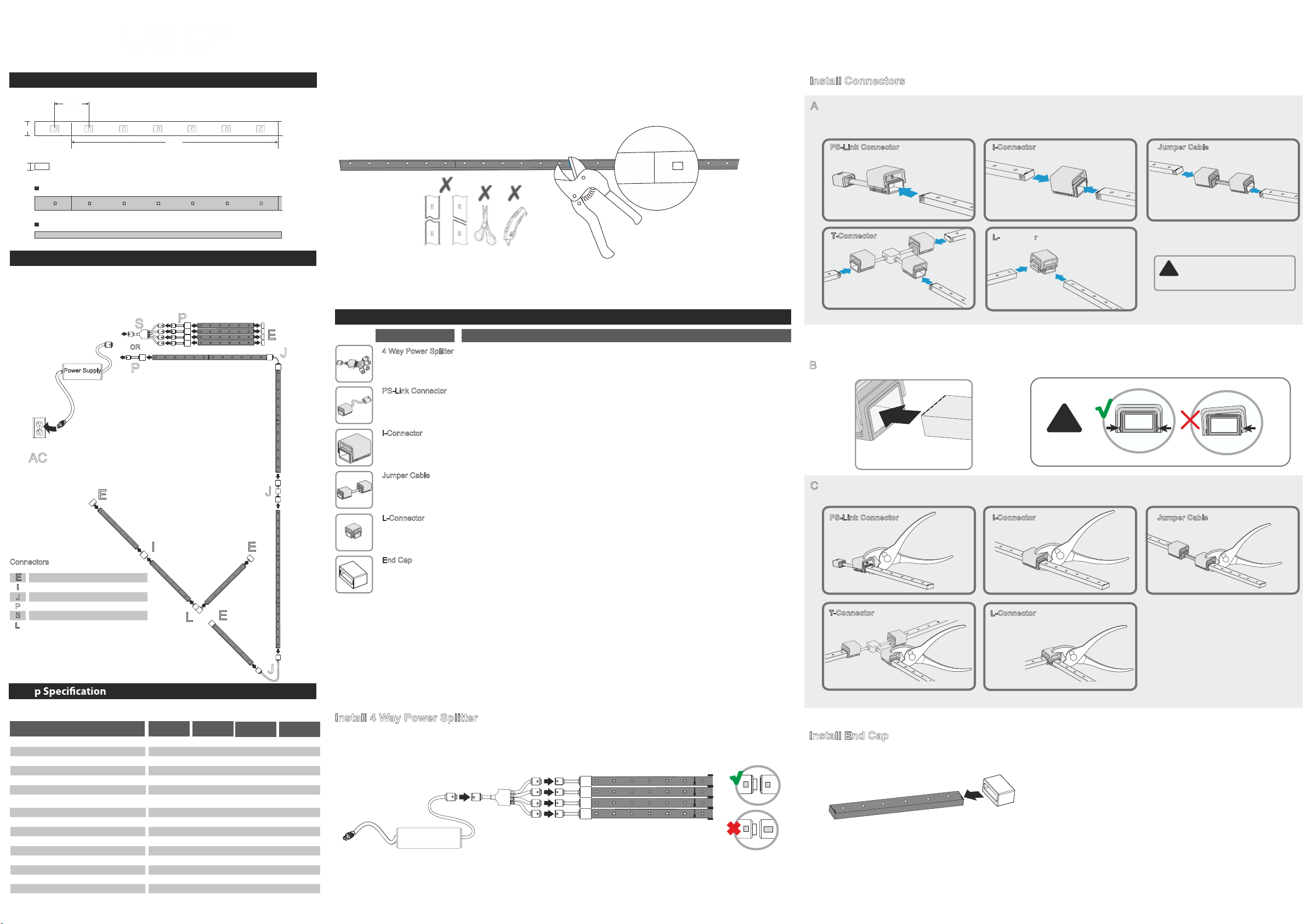
IMPORTANT: The connectors consist of two parts, a top and bottom, which are partially assembled at the factory. DO NOT push the connectors together before you are ready to install.
IP68IP65IP20
IMPORTANT: When using pliers that do not cover the entire surface of the connector, hold the connector and strip steady so the strip remains in position. Carefully rotate the pliers and apply pressure to each side of the connector, pushing the top and bottom together.
IMPORTANT: There is only one way to connect the 4 Way Power Splitter to the power supply and PS-Link Connectors. Make certain the icons match before connecting. Connect the 4 Way Power Splitter to the PS-Link Connectors and to the power supply BEFORE plugging the power supply
into the AC outlet.
IMPORTANT: The 2000 system is designed to work ONLY with the power supplies, connectors, mounting options, and accessories listed. Do NOT substitute other products as they may damage your system.
IMPORTANT: The strip may ONLY be cut every 25cm, indicated by a cut line on the LED side of the strip. When you are measuring for your installation, if the total length in inches is not a multiple of 7, then adjust the plan of your layout to use the nearest cut line marked on the strip.
IMPORTANT: Use Garden Stakes where strip will be installed on the ground outside. Install so strip or connectors will NOT be submerged in water.
IMPORTANT: The light source of this luminaire is not replaceable; when the light source reaches its end of life the whole luminaire shall be replaced.
IMPORTANT: There is only one way to connect the PS-Link Connector to the power supply. Make certain the icons match before connecting. Connect the power supply to the PS-Link Connector BEFORE plugging the power supply into the AC outlet.
Recommended Power Supply Recommended Length of Strip
8W
Warranty : Please contact local RZB office or distributors for more information.
*Technical data are based on optimum conditions and actual performance may vary.
The light source of this luminaire is not replaceable; when the light source reaches its end of life the whole luminaire shall be replaced.
Matching the icons, connect the PS-Link connector to the
≤3.6M / 11.8Ft
≤2M / 6.56 Ft
≤1,75M / 5.74 Ft
TUBEX SVERIGE
Bergkallavagen 34 192 79
Sollentuna Sweden
Telefon: +46 8 544 011 11
15 Watt 24VDC
18 Watt 24VDC
30 Watt 24VDC
60 Watt 24VDC ≤7.5M / 24.6Ft