Turbo Energy HV Lithium Series User manual

https://www.turbo-e.com/
Instruction
Manual
HV Lithium Series 48V 2,4 kWh Battery

2
Read this manual before installing the battery and follow the instructions
carefully during installation process.
Content
1. Scope ...................................................................................................................... 3
2. Specifications.......................................................................................................... 3
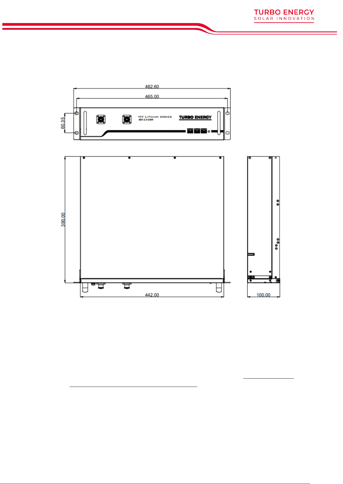
3. Battery Dimensions ................................................................................................. 4
4. Features................................................................................................................... 4
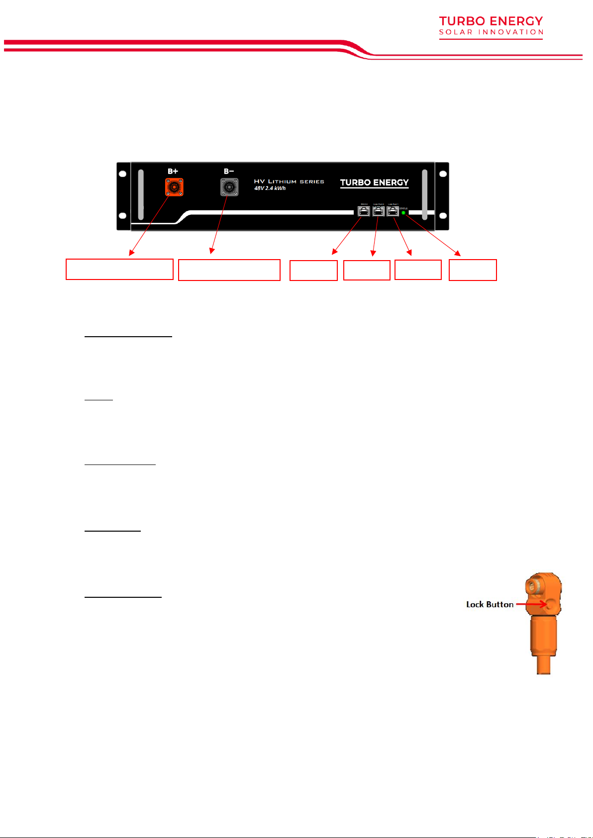
5. Operation................................................................................................................ 5
5.1. Battery Front ..................................................................................................... 5
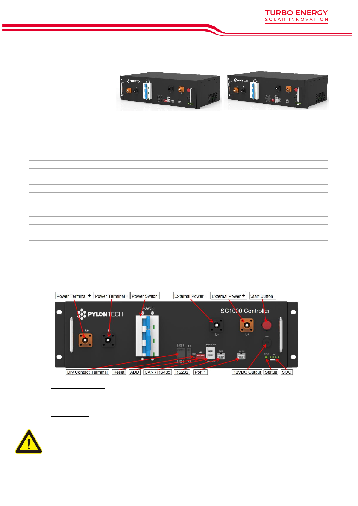
5.2. Control Module ................................................................................................ 6
5.3. Assembly and Connection.............................................................................. 9
5.3.1. Safety..........................................................................................................9
5.3.2. Items in the pack ..................................................................................... 11
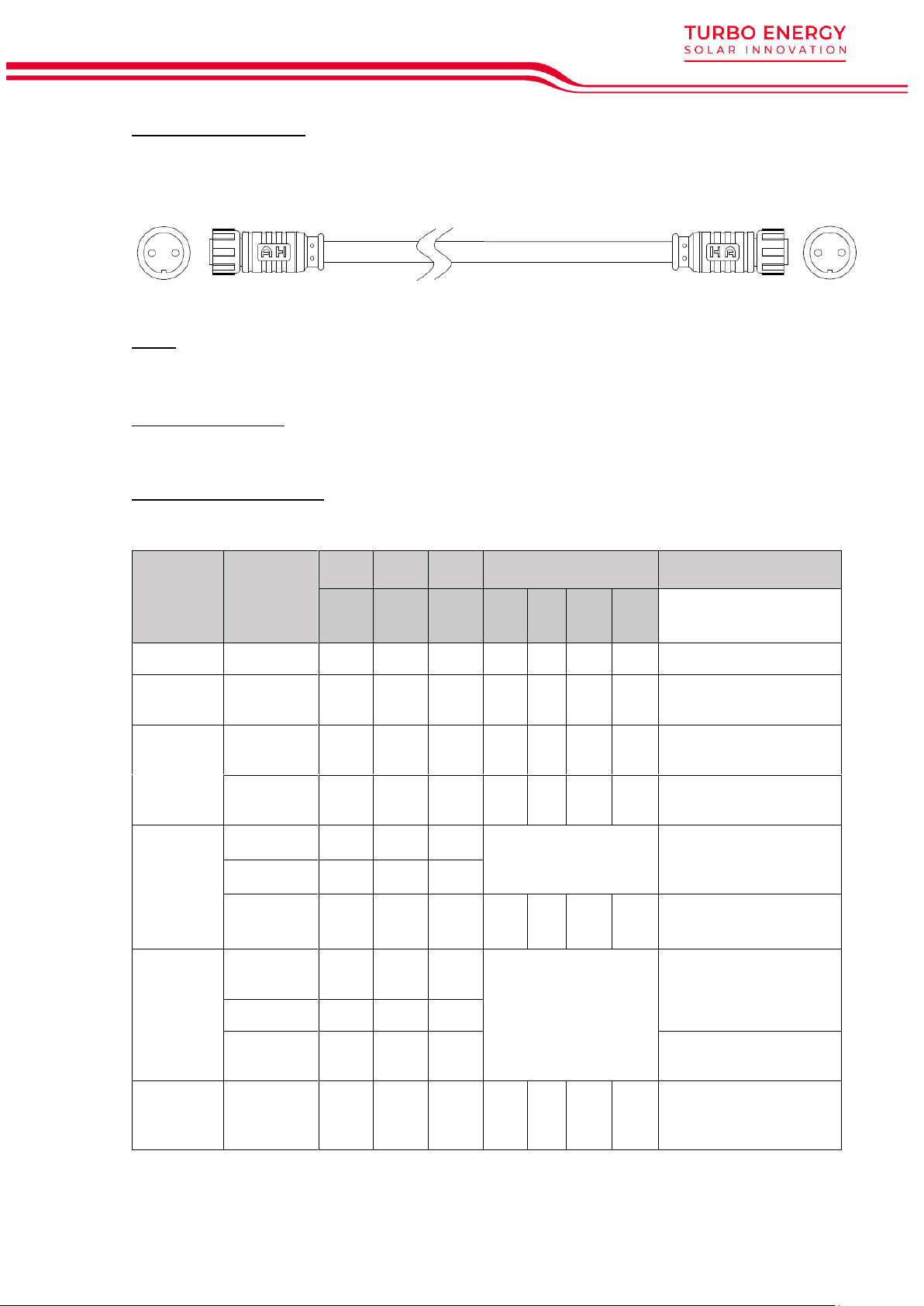
5.3.3. Connections............................................................................................. 12
5.3.4. System Diagram...................................................................................... 15
5.4. Configuration of communications ............................................................... 15
5.4.1. Communication for single BMS (battery string qty. 1 set).................... 16
5.4.2. CAN Communication Mode between MBMS and BMS (battery string
qty. ≤6 set).......................................................................................................... 16
5.4.3. Multi MBMS Communication Mode ....................................................... 17
5.5. Power ON and OFF ........................................................................................ 17
5.5.1. Power ON ................................................................................................. 17
6. System Debug....................................................................................................... 20
7. Trouble Shooting ................................................................................................... 21
8. Appendix............................................................................................................... 23
8.1. Security instructions ........................................................................................ 23
8.2. Safety Warnings.............................................................................................. 23
8.3. Environmental Protection .............................................................................. 24
8.4. Contact Details .............................................................................................. 24

3
1. Scope
This document describes the basic operation of the Turbo Energy brand lithium-
ion rechargeable battery (High Voltage Lithium Series 2.4 kWh model). This
manual contains all the necessary details for understanding the operation of the
equipment and for its correct application.
2. Specifications
HV LS 48V 2,4kWh
Electrical
Nominal Capacity (kWh)
2,40 kWh
Nominal Capacity (Ah)
50 Ah
Nominal Voltage
48V
Cell Voltage
3.2V
Cell Capacity
25 Ah
Charge upper-Voltage
54V
Discharge lower-Voltage
43.5V
Cycle Life
5000 (25ºC)
Physical
Weight
24 kg
Dimensions
442 x 390 x 100 mm
Protection Class
IP20
Battery Type
Li-iron (LFP)
Operation
Max charge/discharge current
50A
Operating Temperature Range
0ºC…50ºC
Storage Temperature
-20ºC…60ºC
Humidity
5%-95%
Other
Transportation Certificate
UN38.3
Battery Cell Quantity (pcs)
30
Battery Module Cell Quantity in Series(pcs)
15
Communication
Compatible CAN y RS-232

4
3. Battery Dimensions
•HV LS 48V 2.4 kWh
4. Features
The HV Lithium Series 48V 2,4 kWh battery has the following features:
•Designed for use in photovoltaic applications.
•Control Module SC0500-100S and SC1000-100S: The control module
manufactured by Pylontech is necessary to monitor batteries operation
and not allowing them to work outside the bounds of the design regime
(V,I).
•Expandability: The system's accumulation capacity can be expanded by
incorporating more batteries.

5
5. Operation
5.1. Battery Front
Power Termina +/-
To connect battery series power cables.
Status
Status light: to show the battery module’s status (RUN●, Alarm● and Protection●).
RS232 Terminal
Console Communication Terminal: (RJ45 port) follow RS232 protocol, for manufacturer
or professional engineer to debug or service.
Link Port 0,1
Link Port 0, 1 Communication Terminal: for communication between multiple serial
battery modules and control module.
Power Terminals
Power cable terminals: there are two pair of terminals with same function,
one connects to equipment, the other one paralleling to other battery
module for capacity expanding. For each single module, each terminal
can achieve charging and discharging function.
For power cables uses AMPHENOL connectors. Must keep pressing the
Lock Button during pulling out the power plug.
Power terminal +
Power terminal -
RS232
Port 0
Status
Port 1

6
5.2. Control Module
SC0500 & SC1000:
Power Terminal +/-
To connect battery power cables in series.
Power Switch
Switch the battery system’s (control module and high voltage DC power) ON/OFF.
Caution: When the breaker is tripped off because of over current or short circuit, must
wait after 30min to turn on it again, otherwise may cause the breaker damage.
SC0500-100S
SC1000-100S
Related Product
HV LS 48V 2.4/3.5 kWh BP
Controller Working Voltage
100~430Vdc
200~1000Vdc
System Operation Voltage(Vdc)
100~430Vdc
200~1000Vdc
Charge Current(Max.)(A)
100
100
Discharge Voltage(Vdc)
100~430Vdc
200~1000Vdc
Discharge Current(Max.)(A)
100
100
Self-consumption Power(W)
8
8
Dimension(W*D*H,mm)
442*390*132
442*390*132
Communication
Modbus RTU\CAN
Modbus RTU\CAN
Protection Class
IP20
IP20
Weight(kg)
7
8.5
Operation Life(Years)
15+
15+
Operation Temperature(℃)
-20~65
-20~65
Storage Temperature(℃)
-40~80
-40~80
Product Certificate
TUV, CE
TUV, CE

7
External Power Terminal +/-
Connect battery system with Inverter.
Dry Contact Terminal
Dry Contact Terminal: provided 2 input and 4 output dry contact signal.
Reset
Reset Button: Long press this button to restart the battery system.
ADD
ADD Switch is a 6 bit dial switches to manually distribute the communication address
of the battery system. Nether position is OFF, means “0”. Upper position is ON, means
“1”. For BMS, 1st bit to 5th bit is for address allocation, and the 6th bit dial switch support
a 120Ωresistance (Terminal Resistance).
Start
Start function: press more than 5sec until the buzzer rings, to turn on controller.
Black start function: when system turned on and during self-check process, , press and
hold the start button again for more than 5sec, and relay will close for 10 min
CAN / RS485
CAN Communication Terminal: (RJ45 port) follow CAN protocol, for communication
between battery system and Inverter.
RS485 Communication Terminal: (RJ45 port) follow Modbus RTU protocol, for
communication between battery system and Inverter.
RS232 Terminal
Console Communication Terminal: (RJ45 port) follow RS232 protocol, for manufacturer
or professional engineer to debug or service.
Link Port 1
Link Port 1 Communication Terminal: (RJ45 port) for communication between multiple
serial battery modules and control module.
Definition of RJ45 Port Pin
No.
CAN
RS485
RS232 Pin
1
---
---
---
2
GND
---
---
3
---
---
TX
4
CANH
---
---
5
CANL
---
---
6
---
GND
RX
7
---
RS485A
---
8
---
RS485B
GND

8
12VDC Output Terminal
Power supply for 3rd level control module, with 12VDC cable:
Status
Status light: to show the battery module’s status (RUN●, Alarm● and Protection●).
LED Status Indicators
Battery capacity indicator: 4 green lamps, each light represents 25% capacity.
LED Indicators Instructions
Battery
Statues
Protection /
Alarm /
Normal
RUN
ALM
PRC
Capacity SOC
Descriptions
●
●
●
●
●
●
●
Shut Down
Off
Off
Off
Off
Off
Off
Off
All off
Sleep
Normal
Flash
1
Off
Off
Off
Off
Off
Off
Indicates Sleep Mode,
to save the power.
Standby
Normal
Flash
1
Off
Off
Off
Off
Off
Off
Indicates Standby
mode.
Alarm
Off
Light
Off
Off
Off
Off
Off
Indicates the battery is
low or high
Charge
Normal
Light
Off
Off
The highest capacity
indicator LED flashes
(flash 2), others lighting
The highest capacity
indicator LED flashes
(flash 2), others lighting
Alarm
Off
Light
Off
Protection
Off
Off
Light
Off
Off
Off
Off
Stop charging, PRC
lighting
Discharge
Normal
Flash
3
Off
Off
Indicate based on
capacity
Indicate based on
capacity
Alarm
Off
Light
Off
Protection
Off
Off
Light
Stop discharging, PRC
lighting
Abnormal
Protection
Off
Off
Light
Off
Off
Off
Off
Stop
charging/discharging,
PRC lighting

9
Note: The flashing instructions, flash 1 –0.25s light / off 3.75 seconds; flash 2 - 0.5s light /
0.5s off; flash 3 - 0.5s light / 1.5s off.
5.3. Assembly and Connection
5.3.1. Safety
The following tools are required to install the battery pack:
Wire Cutter
Crimping Modular Plier
Cable Ties
Screw Driver Set
Electric Screw Driver
Adjustable Wrench
Sleeve Piece
1000VDC Multimeter
NOTE
Use properly insulated tools to prevent accidental electric shock or short circuits.
If insulated tools are not available, cover the entire exposed metal surfaces with
available insulated alternatives, except their tips, with electrical tape.
Safety Gear
It is recommended to wear the following safety gear when dealing with the battery pack.
Insulated gloves Safety goggles Safety shoes

10
Cleaning
The battery system has high voltage connectors. The clean condition will cause the
isolation characteristic of the system.
Before installation and system working must clean the dust and iron scurf to keep the
environments cleaning. And the environment must have certain anti-dust ability.
The system after long term running must check the humidity and dust cover or not. If
heavy dust cover with high humidity on the system should stop the system running and
make clean specially for the high voltage connectors.
Danger: the power cables and plugs still have high voltage DC power from serial
connected battery modules (battery module can’t be turned off), must be
careful to handle the Power Plugs.
Temperature
System working temperature range: 0℃~50℃; Optimum temperature: 18℃~28℃.
Caution: Out of the working temperature range may cause the battery reduces the cycle
of life even cause the battery system over / low temperature alarm or protection.
Cooling System
The room must be equipped with cooling system.
Caution: Out of the working temperature range may cause the battery reduces the cycle
of life even cause the battery system over / low temperature alarm or protection.
Heating System
The room must be equipped with heating system. If the environment is lower than 0℃,
must turn on the heating system at first.
Caution: Out of the working temperature range may cause the battery reduces the cycle
of life even cause the battery system over / low temperature alarm or protection.
Fire-extinguisher System
The room must be equipped with fire-extinguisher system for lithium-ion battery.
The fire system needs to be regularly checked to be in normal condition. Refer to the
using and maintenance requirements of local fire equipment relevant.
Grounding System
Before the battery installation must sure the grounding point of the basement is stable
and reliable. If the battery system is installed in an independent equipment cabin (e.g.
container), must make sure the grounding of the cabin is stable and reliable.
The resistance of the grounding system must ≤100mΩ

11
5.3.2. Items in the pack
1) Battery module - Controller:
Power Cable + (Battery Module
and Main Controller Serial
Connection)
Orange/0.16m/4AWG/2 Orange
Surlok Terminal
1pcs
/module
Power Cable - (Battery Module
and Main Controller Serial
Connection)
Black/2m/4AWG/2 Black Surlok
Terminal
1pcs
/system
Power Cable (Battery Module
Upper and Lower Serial
Connection)
Orange/0.18m/4AWG/1 Orange &
1 Black Surlok Terminal
1pcs
/system
Battery Cascade
Communication Cable (0.18m)
Black/0.18m/8 Core Super 5th
Class Twisted-pair Wire/RJ45
1pcs
/module
External Battery CAN
Communication Cable (direct)
Black/3.5m/Super 5th Class
Twisted-pair Wire/2 RJ45 terminal
1pcs
/system
160
2000
180
180
3500

12
2) Inverter - Controller:
External Power Cable +
Orange/2m/4AWG/SURLOK
Terminal/25-8 Terminal
pcs
1
External Power Cable -
Black/2m/4AWG/SURLOK
Terminal/25-8 Terminal
pcs
1
5.3.3. Connections
Batteries may be connected in series. All batteries must be grounded. It is
suggested to connect the installation ground to the rack (in case it exists) at the
same point as all battery lands.
2000
2000
INVERTER

13
In case of more than one pack (batteries + controller, ≤6 sets) it is necessary to
use MBMS by Pylontech:
MBMS1000
Operating voltage range
12 Vdc
Communication interface
CAN/RS485
Output dry contact interface
4 groups
Input dry contact interface
2 groups
System Consumption
2W
Size
442*190*44mm
Protection degree
IP20
Weight (kg)
5
Working temperature
-20~60
℃
Storage temperature
-40~80
℃
LED indicators instructions:
Battery
Statues
Protection /
Alarm /
Normal
RUN
ALM
PRC
Capacity OC
Descriptions
●
●
●
●
●
●
●
Shut Down
Off
Off
Off
Off
Off
Off
Off
All off
Sleep
Normal
Flash
1
Off
Off
Off
Off
Alarm
Light
Off
Off
Off
Off
Standby
Normal
Flash
1
Off
Off
Off
Off
Off
Off
Indicates Standby
Charge
Normal
Light
Off
Off
The highest capacity
indicator LED flashes
(flash 2), others lighting
Alarm
Off
Light
Off

14
Protection
Off
Off
Light
Off
Off
Off
Off
Stop charging, ALM
lighting
Discharge
Normal
Flash
3
Off
Off
I
n
di
cate
ba
sed
on
capacity
Protection
Off
Light
Light
Off
Off
Off
Off
Stop discharging, ALM
lighting
Connection between different controllers and MBMS will be like follows:

15
5.3.4. System Diagram
•Diagram between BMS and battery modules:
•Multiple battery string parallel connection via CAN communication between
MBMS and BMS diagram (battery string qty. ≤6 sets)
5.4. Configuration of communications
ADD Switch BMS is a 6 bit dial switches to manually distribute the
communication address of the battery system. Nether position is OFF,
means “0”. Upper position is ON, means “1”. 1st bit to 5th bit is for address,
and the 6th bit dial switch support a 120Ωresistance (Terminal Resistance).

16
ADD Switch MBMS is a 6 bit dial switches to manually distribute the
communication address of the battery system. Nether position is OFF,
means “0”. Upper position is ON, means “1”. 1st bit to 4th bit is for address,
the 5th and the 6th bit dial switch support a 120Ωresistance (Terminal
Resistance).
5.4.1. Communication for single BMS (battery string qty. 1 set)
The BMS’s first five bits must set in below <BMS’s Address Configure Table>. The last BMS’s
terminal resistance must set in “1” (X=1).
The address is configured follow ASCII code: (“X” is terminal resistance).
BMS’s Address Configure Table:
5.4.2. CAN Communication Mode between MBMS and BMS (battery string qty.
≤6 set)
The BMS’s first five bits must set in below <BMS’s Address Configure
Table>. The last BMS’s terminal resistance must set in “1” (X=1), and other
BMS’s terminal resistance must set in “0”.
The address is configured follow ASCII code: (“X” is terminal
resistance).
BMS’s Address Configure Table:
The MBMS’s ADD Switch set with “000011”. The last 2 bits are terminal
resistances.
CAN Modbus Address dial bit
0 1 00000X
1 1 10000X
2 2 01000X
3 3 11000X
4 4 00100X
5 5 10100X
6 6 01100X
Battery
String Address Bit Battery
String Address Bit
110000X 910010X 17 10001X 25 10011X
201000X 10 01010X 18 01001X 26 01011X
311000X 11 11010X 19 11001X 27 11011X
400100X 12 00110X 20 00101X 28 00111X
510100X 13 10110X 21 10101X 29 10111X
601100X 14 01110X 22 01101X 30 01111X
711100X 15 11110X 23 11101X 31 11111X
800010X 16 00001X 24 00011X 32 00000X

17
5.4.3. Multi MBMS Communication Mode
In some project it configures multi Energy Storage Systems. In this case
will have multi MBMS. The address of MBMS must follow <MBMS’s Address
Configure Table>
5.5. Power ON and OFF
5.5.1. Power ON
Double check all the power cable and communication cable.
Warning: MBMS must be turned on after all battery strings self-check finish.
Warning: The external switch or breaker between PCS and battery string must be off
before the battery system power on.
System turns on step:
(1) Switch the external power or inverter/PCS on, to make sure all the power equipment
can work normally.
(2) Turn on the 1st BMS (Battery Control Modules) of battery string:
The second BMS must be operated after the first battery string’s self-check is
successful.
From 1st BMS to the last BMS Then turn on the battery strings on one by one.
⚫Turn on the “POWER SWITCH”:

18
Caution: The time interval between every time switch OFF/ON the “Power Switch” shall
>3 minutes.
Caution: When the breaker is tripped off because the system has over current or short
circuit, must after 30min to turn on it again, otherwise may cause the breaker
damage.
⚫Turn on the “Start Button”:
Press and hold the Start Button for more than
5 secs until the buzzer rings, the LED indicator
on front panel will light on if the start-up is
successful.
⚫System start process:
The battery string’s system will check itself, if work normal the battery string system will
go to self-check mode.
If the BMS and all battery modules are working normally, every status LED will
lighting green, that’s mean self-check are pass. Normally the self-check will be
finish within 30sec.
If long press the start button again within 30s during BMS self-check, the“STATUS”
lamp will flash red, it is to remind that the black start function is activated within
30s for 10min.
If MBMS is using internal power supply from BMS, please first use black start
function to provide power supply to MBMS, for further establish the external
communication.
If there is no communication from upper equipment because of the
communication is off, the “STATUS” lamp will light red after 30sec. That doesn’t
means failure existed, it means this battery string is OK while the external
communication is off.
Warning: If has failure during the self-check, must debug the failure then can start next
step.
If the “STATUS” lamp shows red from beginning, it means has failure in the battery
string, the Power Relays in BMS will switch ON, must debug at first.
Caution: During first time power on, the system will require to do fully charge progress for
SOC calibration purpose.
Caution: The whole Battery Energy Storage System (BESS) after installation or restart the
system when long time not in using should charge it to full at first. There will be a
regularly fully charge requesting during continuous operation as well, it will be
handled automatically by the communication between BESS and external
device.

19
Warning: if the black-start function is used, the terminal of DC “+” and DC “-” will
be electricity dangerous with high DC voltage output.
(3) Switch the MBMS on after all the BMS turn on successful:
And check whether MBMS is working. The “STATUS” lamp will light green.
When the voltage difference between strings is smaller than the parameter, the
battery string will do the parallel operation. Then the power relays in BMS will
switch ON after 30 seconds. The “STATUS” lamp of the BMS will light green;
When the voltage difference between strings is bigger than the parameter, the
battery string will NOT do the parallel operation, the “STATUS” lamp of the BMS
will light red, but it is normal; Such battery string will be paralleled in during
charging stage automatically.
Note: If there is no communication between MBMS and upper controller, the
system can’t work normally. External device should communicate with battery
system through LAN, CAN or RS485. Otherwise maybe cause battery system work
abnormal.
Caution: During first time power on, the system will require to do fully charge progress for
SOC calibration purpose.
Caution: The whole Battery Energy Storage System (BESS) after installation or restart the
system when long time not in using should charge it to full at first.
There will be a regularly (3 month) fully charge requesting during continuous operation
as well, it will be handled automatically by the communication between BESS
and external device.
5.5.2. Power OFF
When failure or before service, must turn the battery storage system off:
(1) Soft-off the PCS through PCS’s control panel.
(2) Turn off the switch between PCS and battery string, or turn off the power switch of
PCS, to make sure no current transmission through battery string and PCS.
(3) Turn off the “Power Switch” of the BMS.
(4) Turn off the “Power Switch” of the MBMS. If the ESS configures only single battery
without MBMS, then ignore this operation step.
(5) Turn off the UPS if configured.
The UPS can turn on if have equipment must keep running. Otherwise suggest turn off
the UPS to save power.
Caution: Before change the battery module for service, must charge/discharge the
replaced battery to same voltage as the other modules in the system. Otherwise system
needs long time to do the balance for such replacment module.

20
Warning: Do not turn off the “Power Switch” during normal running condition. Otherwise
will cause this battery string current surge by another battery strings. If turned off the
“Power Switch” in normal running condition, must first turn off the PCS.
6. System Debug
This system debug is for BESS system (Battery Energy Storage System). BESS system
cannot do the debug itself. It must operation with configured UPS, PCS, and EMS
system together.
Debug Step
Content
Prepare of debug.
Turn on the BESS system, refer to chapter 3. Before turning on
the whole BESS system turn on the load is not allowed!
Remark: Except the BESS, if other equipment has its own
system turn on step, must follow its own system operation
manual.
System function test.
Each component system debug:
Power supply Check if the External Power Supply (e.g., UPS)
is working normally.
Communication Test: Check the communication between
the BESS system and communicated devices normal or not,
has alarm or not.
Power Conversion System Test: Before conjoint test must test
the Inverter System turn on progress at first. And check the
parameters meet BESS requirement or not.
BESS Test: Charge/Discharge test; Test stop charging, stop
discharging, current limiting functions, etc.
Caution: Before turning on the BESS system must setup all the
parameters of the PCS and EMS at first.
Monitor function test.
(If configured.)
Check whether the data of the BESS system is showing on
the monitor system normally.
EMS conjoint test
(If configured.)
If the EMS system has running monitor requirements, check if
the BESS system is following EMS instructions.
Trial operation test.
After the system debugged, run the system a period as test
(testing with low load), to test the high voltage DC system is
fit for the contract.
This manual suits for next models
1
Table of contents
Other Turbo Energy Camera Accessories manuals

Turbo Energy
Turbo Energy Lithium Series User manual

Turbo Energy
Turbo Energy Lithium Series User manual

Turbo Energy
Turbo Energy Lithium Series User manual

Turbo Energy
Turbo Energy Lithium Series User manual

Turbo Energy
Turbo Energy Lithium Series User manual

Turbo Energy
Turbo Energy Lithium Series User manual