TURBO RACING 91803G-VT User manual

Congratulations on your purchase of Turbo Racing 91803G-VT 3-Channel Radio
System. Designed using advanced wireless technology, Turbo Racing 91803G-VT
will advance and simplify control of your suface model and minimize interference
while providing many years ofenjoyment.
This product is not a toy! (14+) Recommended for ages 14 and up.
Adult supervision required for ages under 18 years old. Contains small
parts, keep out of reach of children 3 years of age and younger.
MADE IN CHINA
www.blqhobby.com
Please read this manual carefully prior to using.We are not
responsible for any intentional damage or improper use.lf
you require any additional information or have any quesions
adout he product or its use,please contact us via
www.blqhobby.com
INSTRUCTIONS MANUAL
91803G-VT
AAA x4
137.00
3CH
162.30
68.60
Turbo Racing 91803G-VT 3-Channel Radio System is warranted to the original purchaser for 30 days
from the date of purchase, verified by the sales receipt, againsr defects in material and workmanship.
Product that has been mishandled, abused, used incorrectly, used for an application other than intended
or damaged by the user is not covered under warranty. Turbo Racing. is not liable for any loss or
damage, whether direct or indirect, incidental or consequential, or from any special situatuon, arising
from the use, misuse, or abuse of this product.
AUX 3 2 1
91803G-VT

1. Steering Wheel: Controls left / right motion (note that
left-hand use (see full online manual for details).
2. Throttle Trigger: Controls forward / reverse / brake
3. Hand Grip: For holding the transmitter.
4. Antenna: Transmits signal to the receiver located in the
vehicle.
5. Power switch: Turns the transmitter ON / OFF.
6. Disassemble key:Handle is removable.
7. ST DR/ST TRIM: Please turn the wheel to left or right with
Max angle, and press ST-TRIM+ or ST-TRIM-, then adjust
the angle of ST
8. TH DR/TH TRIM: Please pull the throttle or push the throttle
to Max position, and press TH-TRIM+ or TH-TRIM-, then
adjust the angle of TH
Battery compartment: Houses [4] AAA batteries or a NiMH9.
10. Channel 3 key.
11. Multifunction Red Indicator LED:
12. REV:
(1). Please turn the wheel to left or right with Max angle , and
press REV for 2 seconds, then ST will be reverse.
Disassemble Handle & Install
INSTRUCTIONS MANUAL
www.blqhobby.com
(2). Please pull the throttle or push the throttle to Max position ,
and press REC for 2 seconds, then REV will bereverse
1.Press the button
2.take away the handle
3.press the button, install the handle

Pairing The Transmitter & Receiver
CAUTION: NEVER CONNECT A BATTERY WITH VOLTAGE
HIGHER THAN 6.0V TO THE RECEIVER, DOING SO COULD
DAMAGE THE ELECTRONICS.
INSTRUCTIONS MANUAL
www.blqhobby.com
Connection
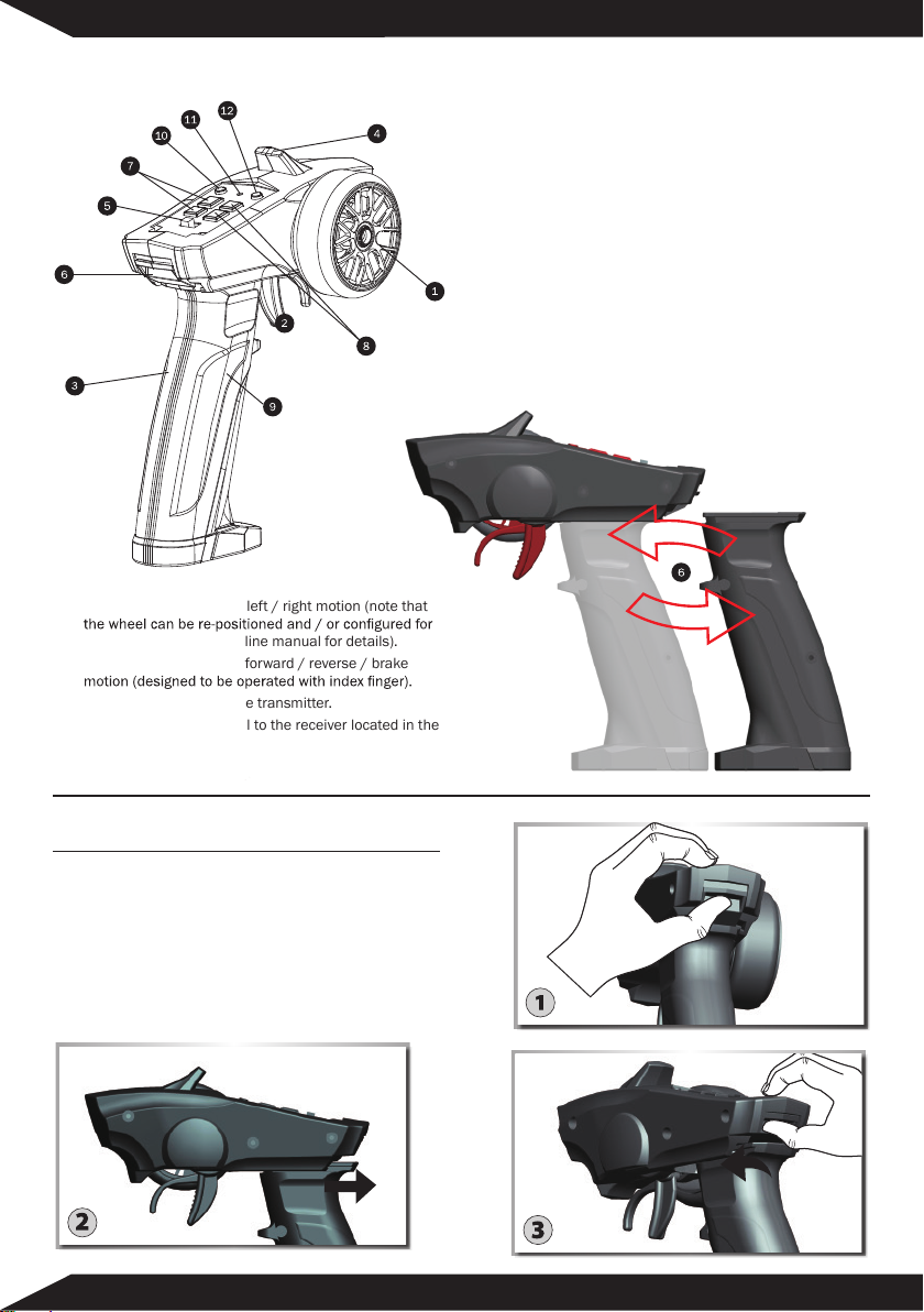
• Channel 1: Controlled by the wheel, connect to a servo
for steering.
• Channel 2: Controlled by the trigger, connect to the
ESC or a servo for throttle/brake.
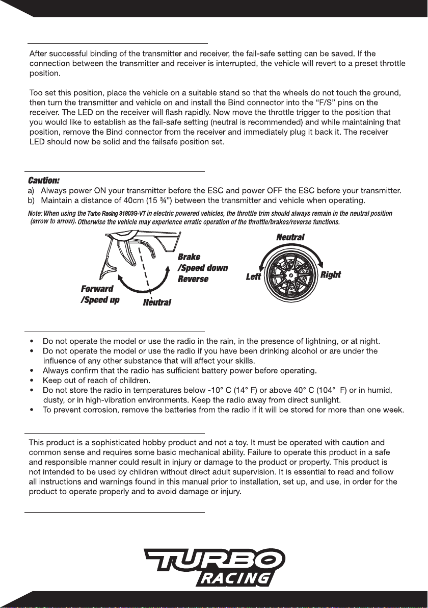
• Channel 3: Controlled by the adjustment knob
(0-100%) for optional use. This port can also be used
to connect a transponder device used in racing.
• AUX (Channel 4): Controlled by button (ON/OFF) for
optional use. This port is most commonly used for LED
light kits. Use this port to connect an external battery
for use with gas powered vehicles.
Electric powered model
Battery Installation
Using the AAA batteries or NIMH batteries, when the voltage
is lower than 4.5V ±0.2, the buzzer sounds continuously,
and the LED should start flashing.
1. Remove the battery cover
from the transmitter.
2. Insert four new AAA batteries
according to the polarity
markings on the battery holder.
3. Reinstall the battery cover.
WARNING: DO NOT ATTEMPT TO CHARGE NON-RECHARGEABLE
BATTERIES, YOU MAY CAUSE AN EXPLOSION.
WARNING: PLEASE DON'T RESERVE THE BATTERY,OR IT WILL
BURN OUT THE PCB
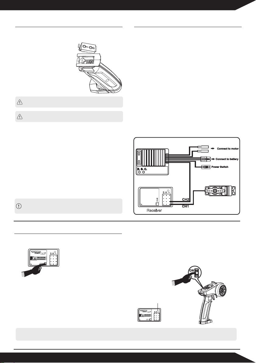
Receiver Installation & Connection
Installation
To achieve full operating range with your radio system it
is critical that the receiver antenna be undamaged and
installed properly. It should be installed with as much of
the antenna as possible in a vertical position. The end of
the antenna should be contained inside an antenna tube.
When installing:
• Ensure there are no kinks in the antenna or antenna
tube.
• Never fold the end of the antenna over the tube, this
will reduce the operating range of the system and
damage the antenna.
• Ensure the receiver is mounted securely or padded
against hard impacts.
AUX 3 2 1
ESC
Steering Servo
Receiver
AUX 3 2 1
AUX 3 2 1
LED
1. After connecting the reciver to a power source (receiver battery or ESC) and turning it on, connect the SW connector to the “
Pair” Pins on the receiver. The LED on the receiver will flash rapidlt.
2. Switch on the teansmitter, and then remove the Bind connector from the receiver.
Note: Radio systems installer in RTRs have already been bound. Only when installing a new transmitter or receiver is the
above process necessary
3. The LED on the receiver will now remain solid to indicate successful dinding of
the transmitter and receiver

Failsafe Function Setting
www.blqhobby.com
INSTRUCTIONS MANUAL
newstone technology co., ltd
Operation
Using Caution While Operating
Safety Precautions
General Care
1. Always use clean, dry cloth or soft bristle brush to clean your equipment.
2. Never use chemical cleansers, as these could damage the sensitive electronics and plastics.
Table of contents