Turbo ECONET EC+ Installation and operating instructions

A P P L I C AT I O N N O T E
E C O N E T E C + / E C + + E th e r n e t & W i F i C o n f i g u r a t i o n
A P N t 0 2 4 E C W E C
EN R e v . 1 . 0 3
T U R B O s . r . l . D u s t F i l t e r C o m p o n e n t s
V i a C e n t r o I n d u s t r i a l e E u r o p e o , 3 3 –T u r a t e ( C O ) I t a l y
T e l + + 3 9 0 3 6 2 5 7 4 0 2 4 Fa x + + 3 9 0 3 6 2 5 7 4 0 9 2
1
ECONET EC+ / EC++
Ethernet & WiFi Configuration
Application Note 024
Release 1.03 2021

A P P L I C AT I O N N O T E
E C O N E T E C + / E C + + E th e r n e t & W i F i C o n f i g u r a t i o n
A P N t 0 2 4 E C W E C
EN R e v . 1 . 0 3
T U R B O s . r . l . D u s t F i l t e r C o m p o n e n t s
V i a C e n t r o I n d u s t r i a l e E u r o p e o , 3 3 –T u r a t e ( C O ) I t a l y
T e l + + 3 9 0 3 6 2 5 7 4 0 2 4 Fa x + + 3 9 0 3 6 2 5 7 4 0 9 2
2
Introduction
This application note provides information about configuration methods and features for WiFi® and Ethernet
plug-in communication boards for Econet EC+/EC++ family.
The Turbo plug-in communication boards are available in three mounting variant: WiFi, Ethernet and WiFi +
Ethernet. They are fully compatible with EC+ and EC++ Econet devices and have an on-board TCP/IP stack for
ready-to-use interfacing at standard industrial networks.
Plug-In communication boards
Based on the “Plug-in Communication boards” are made up of a small board fitted into the Econet EC+/EC++
mainboards.
Developed around a single electronic board fitted in different variants, the communication board is mounted
on the Econet EC+/EC++ motherboard. It is provided of an high performances microcontroller that handles a
communication module. Thanks to its smart technology, the module takes care of handling all the information
exchange tasks on the network.
Once the initial configuration has been performed, the Plug-In communication board automatically accesses at
WiFi or Ethernet network and sends/receives serial data.
The WiFi version is based on Microchip RN171 stand-alone embedded wireless LAN access device module.
The Ethernet version is based on Lantronix® DeviceLinx® XPort® device server module.
Here are listed the main Plug-In communication board features:
Ethernet board
WiFi board
Connects devices through a TCP data channel or through
a Telnet connection
Fully qualified and Wi-Fi certified 2.4 GHz IEEE 802.11 b/g transceiver
Supports UDP datagrams
FCC, CE, IC certified
Contains a web [HTTP] server allowing presentation of custom
content and easy configuration through a browser.
4 μA sleep, 35 mA RX, 185 mA TX at 12 dBm
(TX power is configurable)
ARP, UDP, TCP, ICMP, Telnet, TFTP, AutoIP, DHCP, HTTP, and
SNMP for network communications and management.
On-board TCP/IP stack
TCP, UDP, and Telnet for connections to the serial port.
Output Power: 12dBm (programmable)
IP for addressing, routing, and data block handling over the
network.
Secure Wi-Fi authentication via WEP, WPA-PSK (TKIP), and
WPA2-PSK (AES)
User Datagram Protocol (UDP) for typical datagram applications
External antenna

A P P L I C AT I O N N O T E
E C O N E T E C + / E C + + E th e r n e t & W i F i C o n f i g u r a t i o n
A P N t 0 2 4 E C W E C
EN R e v . 1 . 0 3
T U R B O s . r . l . D u s t F i l t e r C o m p o n e n t s
V i a C e n t r o I n d u s t r i a l e E u r o p e o , 3 3 –T u r a t e ( C O ) I t a l y
T e l + + 3 9 0 3 6 2 5 7 4 0 2 4 Fa x + + 3 9 0 3 6 2 5 7 4 0 9 2
3
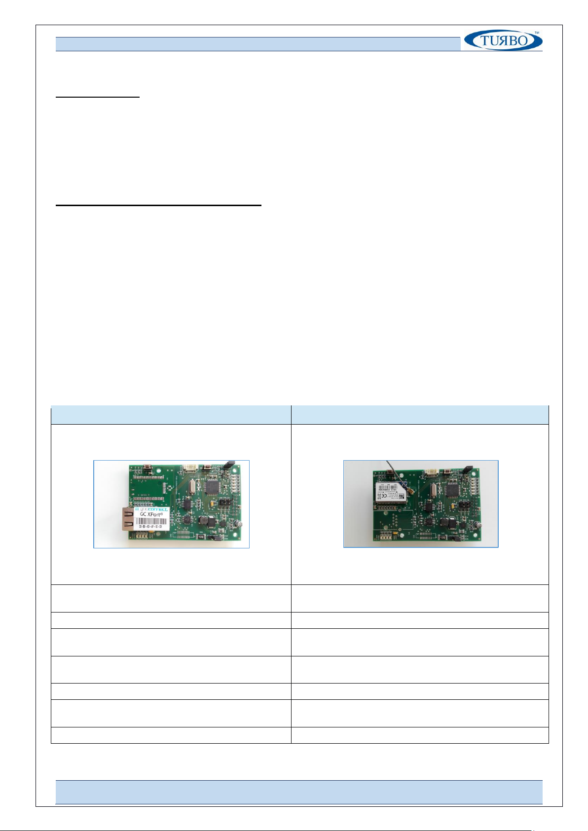
Ethernet board configuration
In order to operate correctly on a network, the Ethernet Plug-In board must have a unique IP address on the
network. To do this, there are two basic methods for logging into the Xport device server to assign an IP
address and configure the module.
Method 1: Using DeviceInstaller
Assign an IP address and view the current XPort module configuration using a Graphical User Interface (GUI) on
a PC attached to a network.
DeviceInstaller is a free utility software provided by Lantronix for configure, upgrade and manages Lantronix
Device Servers. It can be downloaded from the Lantronix website at www.lantronix.com/support/downloads.
For instructions on using DeviceInstaller to configure the IP address and related settings or for more advanced
features, see the DeviceInstaller Online Help.
To install DeviceInstaller:
1. Download the latest version of DeviceInstaller software from Lantronix site;
2. Run the executable to start the installation process;
3. Power ON the Econet device equipped with Ethernet plug-in board;
4. Connect the Ethernet cable at the Ethernet plug-in board header;
5. Check connection by mean of flashing green Leds on the header;
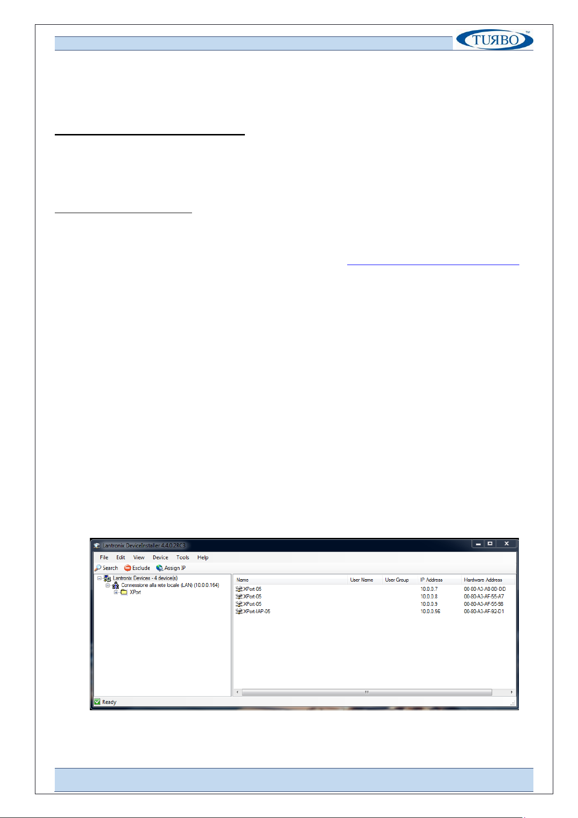
6. Launch DeviceInstaller software;
To Assign IP:
The device’s IP address must be configured before it can work correctly on a network.
Using DeviceInstaller software tool the user can manually assign the IP address over the network. The unit’s IP
address is normally set to 0.0.0.0 at the factory.
1. Double-click on DeviceInstaller.exe to launch the software;

A P P L I C AT I O N N O T E
E C O N E T E C + / E C + + E th e r n e t & W i F i C o n f i g u r a t i o n
A P N t 0 2 4 E C W E C
EN R e v . 1 . 0 3
T U R B O s . r . l . D u s t F i l t e r C o m p o n e n t s
V i a C e n t r o I n d u s t r i a l e E u r o p e o , 3 3 –T u r a t e ( C O ) I t a l y
T e l + + 3 9 0 3 6 2 5 7 4 0 2 4 Fa x + + 3 9 0 3 6 2 5 7 4 0 9 2
4
2. Click Tools → Options → flag ON the Connect to local LAN from the window list;
3. Click Apply and then the OK buttons;
4. Click the Xport folder. The list of available Lantronix Xport device displays;
5. Expand the Xport list and select the RED Xport unit by clicking on its IP address to view its
configuration;

A P P L I C AT I O N N O T E
E C O N E T E C + / E C + + E th e r n e t & W i F i C o n f i g u r a t i o n
A P N t 0 2 4 E C W E C
EN R e v . 1 . 0 3
T U R B O s . r . l . D u s t F i l t e r C o m p o n e n t s
V i a C e n t r o I n d u s t r i a l e E u r o p e o , 3 3 –T u r a t e ( C O ) I t a l y
T e l + + 3 9 0 3 6 2 5 7 4 0 2 4 Fa x + + 3 9 0 3 6 2 5 7 4 0 9 2
5

A P P L I C AT I O N N O T E
E C O N E T E C + / E C + + E th e r n e t & W i F i C o n f i g u r a t i o n
A P N t 0 2 4 E C W E C
EN R e v . 1 . 0 3
T U R B O s . r . l . D u s t F i l t e r C o m p o n e n t s
V i a C e n t r o I n d u s t r i a l e E u r o p e o , 3 3 –T u r a t e ( C O ) I t a l y
T e l + + 3 9 0 3 6 2 5 7 4 0 2 4 Fa x + + 3 9 0 3 6 2 5 7 4 0 9 2
6
6. Select Assign a specific IP address and click Next;
7. Enter the IP address. The subnet mask display automatically based on the IP address. The user may
change it. On a local network, the user can leave the Default gateway blank (all zeros). Click Next.
8. Click the Assign button and wait several seconds until a confirmation message displays. Click Finish.

A P P L I C AT I O N N O T E
E C O N E T E C + / E C + + E th e r n e t & W i F i C o n f i g u r a t i o n
A P N t 0 2 4 E C W E C
EN R e v . 1 . 0 3
T U R B O s . r . l . D u s t F i l t e r C o m p o n e n t s
V i a C e n t r o I n d u s t r i a l e E u r o p e o , 3 3 –T u r a t e ( C O ) I t a l y
T e l + + 3 9 0 3 6 2 5 7 4 0 2 4 Fa x + + 3 9 0 3 6 2 5 7 4 0 9 2
7
9. Select the Xport device IP assigned from main window list and select Ping from the Tool menu. The
results display in the Status Window. Click Clear;
10. Close DeviceInstaller software, then power-Off/On the Econet device;
To Communicate on the network
1. Launch the user software (i.e. Turbo “PC-Panel);
2. Select the TCP/IP communication protocol;
3. Enter the device IP address, the reserved device port=502 and Press OK. The communication starts.

A P P L I C AT I O N N O T E
E C O N E T E C + / E C + + E th e r n e t & W i F i C o n f i g u r a t i o n
A P N t 0 2 4 E C W E C
EN R e v . 1 . 0 3
T U R B O s . r . l . D u s t F i l t e r C o m p o n e n t s
V i a C e n t r o I n d u s t r i a l e E u r o p e o , 3 3 –T u r a t e ( C O ) I t a l y
T e l + + 3 9 0 3 6 2 5 7 4 0 2 4 Fa x + + 3 9 0 3 6 2 5 7 4 0 9 2
8
Method 2: Using Web Manager
Through a web interface, configure the XPort and its settings using the XPort module’s Web Manager.
1. Run DeviceInstaller software tool and search for the list of available Lantronix device servers;
2. Click on the Xport folder and select the Xport unit by clicking its hardware address;
3. In the right pane, click the Web configuration tab and click on the green arrow to load web page;
4. A dialog box appears to prompt for a User name and Password. Press OK to proceed;
5. After few seconds, the Web page displays.
6. Select Network from the main menu on the left side, then enter the IP address and click OK button;
7. Press Apply Settings from the main menu on the left side and wait the end of save procedure.

A P P L I C AT I O N N O T E
E C O N E T E C + / E C + + E th e r n e t & W i F i C o n f i g u r a t i o n
A P N t 0 2 4 E C W E C
EN R e v . 1 . 0 3
T U R B O s . r . l . D u s t F i l t e r C o m p o n e n t s
V i a C e n t r o I n d u s t r i a l e E u r o p e o , 3 3 –T u r a t e ( C O ) I t a l y
T e l + + 3 9 0 3 6 2 5 7 4 0 2 4 Fa x + + 3 9 0 3 6 2 5 7 4 0 9 2
9
WiFi board configuration
In order to operate correctly on a network, the WiFi Plug-In board must have a unique IP address on the
network. To do this, there are two basic methods for logging into the RN171 WiFi device to assign an IP address
and configure the module.
Method 1: Using Econet Serial Port
Assign an IP address and view the current WiFi module configuration using a standard Serial Communication
software installed into a PC attached to the Econet device by mean of RS485 to USB adapter cable.
To configure WiFi module:
Using serial communication software tool (i.e. Docklight V1.9) the user can manually assign the IP address and
set the most important WiFi parameters.
1. Double-click on Serial communication software executable to launch the software;
2. Double-click on COMxx port on the top right side of the toolbar to set the communication port;
3. Connect the RS485 to USB adapter cable at the Econet Serial Port (42-41 terminals), Power-On the
Econet device and start the serial communication software;
4. Using the Serial communication software, send a “$$$”<CR> string and wait the WiFi plug-In board
response;
16/03/2018 15:26:59.661 [TX] - $$$
16/03/2018 15:27:00.731 [RX] - CMD<CR><LF>

A P P L I C AT I O N N O T E
E C O N E T E C + / E C + + E th e r n e t & W i F i C o n f i g u r a t i o n
A P N t 0 2 4 E C W E C
EN R e v . 1 . 0 3
T U R B O s . r . l . D u s t F i l t e r C o m p o n e n t s
V i a C e n t r o I n d u s t r i a l e E u r o p e o , 3 3 –T u r a t e ( C O ) I t a l y
T e l + + 3 9 0 3 6 2 5 7 4 0 2 4 Fa x + + 3 9 0 3 6 2 5 7 4 0 9 2
10
5. Send a “scan”<CR> string to perform a network scan;
16/03/2018 15:25:09.805 [TX] - scan<CR>
<4.41> <CR><LF>
SCAN:Found 3<CR><LF>
01,01,-85,04,1104,28,c0,64:59:f8:dd:11:d8,Vodafone-34318725<CR><LF>
02,06,-67,04,3100,1c,00,46:d9:e7:0d:59:06,TURBO 2<CR><LF>
03,11,-71,04,1104,18,40,30:91:8f:7c:8c:1b,Telecom-59820571<CR><LF>
END:<CR><LF>
6. Send a “set wlan ssid networkname “<CR> string to set the SSID;
16/03/2018 15:30:21.184 [TX] - set wlan ssid networkname<CR>
AOK<CR><LF>
<4.41>
7. Send a “set wlan pass passphrase”<CR> string to set the network password;
16/03/2018 15:32:39.115 [TX] - set wlan pass ###########<CR>
AOK<CR><LF>
<4.41>
8. Send a “set wlan join 1”<CR> string to set the automatic association at the device Power-Up;
16/03/2018 15:34:44.878 [TX] - set wlan join 1<CR>
AOK<CR><LF>
<4.41>
9. Send a “set ip address xxx.xxx.xxx.xxx”<CR> string to set the WiFi plug-In static address;
16/03/2018 15:35:30.678 [TX] - set ip address 10.0.0.58<CR>
AOK<CR><LF>
<4.41>
10. Send a “set ip dhcp 0”<CR> string to force the WiFi plug-In module to use its stored static IP address;
16/03/2018 15:36:10.238 [TX] - set ip dhcp 0<CR>
AOK<CR><LF>
<4.41>
11. Send a “save”<CR> string to store setting into the WiFi plug-In module;
16/03/2018 15:37:34.011 [RX] - ave<CR>
<CR><LF>
Storing in config<CR><LF>
<4.41>
12. Send a “reboot”<CR> string to reboot the WiFi module;
16/03/2018 15:39:34.412 [RX] - boot<CR>
<CR><LF>
*Reboot*wifly-EZX Ver: 4.41 Build: r1057, Jan 17 2014 10:23:54 on RN-
171<CR><LF>
MAC Addr=00:06:66:9c:9b:15<CR><LF>
*READY*<CR><LF>
Auto-Assoc TURBO 2 chan=6 mode=MIXED SCAN OK<CR><LF>
Joining TURBO 2 now..<CR><LF>
Associated!<CR><LF>
Using Static IP<CR><LF>
Listen on 2000<CR><LF>
To Communicate on the network:
1. Launch the user software (i.e. Turbo “PC-Panel);
2. Select the TCP/IP communication protocol;

A P P L I C AT I O N N O T E
E C O N E T E C + / E C + + E th e r n e t & W i F i C o n f i g u r a t i o n
A P N t 0 2 4 E C W E C
EN R e v . 1 . 0 3
T U R B O s . r . l . D u s t F i l t e r C o m p o n e n t s
V i a C e n t r o I n d u s t r i a l e E u r o p e o , 3 3 –T u r a t e ( C O ) I t a l y
T e l + + 3 9 0 3 6 2 5 7 4 0 2 4 Fa x + + 3 9 0 3 6 2 5 7 4 0 9 2
11
3. Enter the device IP address, the reserved device port=2000 (WiFi dedicated) and Press OK. The
communication starts.
Method 2: Using Web Browser
Through a web interface, configure the WiFi plug-In settings using a common Web browser.
1. Power-On the Econet device;
2. Press and release the “S2” pushbutton placed on the WiFi plug-In board;

A P P L I C AT I O N N O T E
E C O N E T E C + / E C + + E th e r n e t & W i F i C o n f i g u r a t i o n
A P N t 0 2 4 E C W E C
EN R e v . 1 . 0 3
T U R B O s . r . l . D u s t F i l t e r C o m p o n e n t s
V i a C e n t r o I n d u s t r i a l e E u r o p e o , 3 3 –T u r a t e ( C O ) I t a l y
T e l + + 3 9 0 3 6 2 5 7 4 0 2 4 Fa x + + 3 9 0 3 6 2 5 7 4 0 9 2
12
3. Check if the led information is switched from “Stand-By mode” to “Launch Soft AP mode”.
Now the WiFly Web-Server is available for configuration activities;
4. Connect the PC or Smartphone at the WiFly open network created by the WiFi piggy-back board;
No password are needed. The WiFly is an open network.
Once the PC or smartphone is connected at the Wifly
Web-Server, the led information will switch from “Launch
Soft AP mode” to “Client associated with AP network”.
5. Open the Web browser on the PC or Smartphone and write http://config.
The led information will switch form “Client associated with AP network” to “Web Browser launched on
the Client”.
A configuration window will appear;

A P P L I C AT I O N N O T E
E C O N E T E C + / E C + + E th e r n e t & W i F i C o n f i g u r a t i o n
A P N t 0 2 4 E C W E C
EN R e v . 1 . 0 3
T U R B O s . r . l . D u s t F i l t e r C o m p o n e n t s
V i a C e n t r o I n d u s t r i a l e E u r o p e o , 3 3 –T u r a t e ( C O ) I t a l y
T e l + + 3 9 0 3 6 2 5 7 4 0 2 4 Fa x + + 3 9 0 3 6 2 5 7 4 0 9 2
13
6. Press “Refresh List” button to refresh the SSID network list;
7. Select your SSID network. It will appear into the “Access Point SSID” text-box. Insert the password into
the “passphrase” text-box and then press the “Save & Reboot” button.
8. Checking the “Display Advanced Tabs”, the user can enable some advanced tabs to access to the
extended information. Accessing “Information” Tab, the WiFi Module-Type and the MAC address will
be displayed.
9. Accessing “Module Cfg” Tab, the Device ID name and the serial port configuration will be displayed;
10. Accessing “Terminal” Tab, the user can configure the WiFi module using the same strings used with
Method1. At the end of strings input, press “Save & Reboot” button to store configuration.

A P P L I C AT I O N N O T E
E C O N E T E C + / E C + + E th e r n e t & W i F i C o n f i g u r a t i o n
A P N t 0 2 4 E C W E C
EN R e v . 1 . 0 3
T U R B O s . r . l . D u s t F i l t e r C o m p o n e n t s
V i a C e n t r o I n d u s t r i a l e E u r o p e o , 3 3 –T u r a t e ( C O ) I t a l y
T e l + + 3 9 0 3 6 2 5 7 4 0 2 4 Fa x + + 3 9 0 3 6 2 5 7 4 0 9 2
14
Appendix A –Revision History
Version draft
First draft
Dec 2017
Version 1.0
First Release
Mar 03, 2018
Version 1.01
Added Led information at Method2 of WiFi board configuration
Nov 05, 2018
Version 1.02
Version 1.03
Added item 10 at page 9 to set dhcp=0 to force to use static IP address
Updated Turbo HQ Address
Nov 13, 2018
Nov 03, 2021
This manual suits for next models
1
Table of contents
Other Turbo Industrial Equipment manuals
Popular Industrial Equipment manuals by other brands

Maxcess
Maxcess TIDLAND Roll Restorer user manual

Bomar
Bomar Easycut Series operating instructions

Bona
Bona Power Drive AS0003201 installation guide

SCHUNK
SCHUNK PGN Assembly and operating manual

Primera
Primera FX1000 Operator's guide

DCL
DCL MINE-X SOOTFILTER ACCOMPANIMENT TO THE INSTALLATION, OPERATION AND MAINTENANCE MANUAL