Turbo E9T Installation and operating instructions

A P P L I C A T I O N N O T E
E 9 T U S A G E I N I N D U S T R I A L F I E L D
A P N t 0 2 6 E 9 T U I F
EN R e v . 1 . 1
T U R B O s . r . l . D u s t F i l t e r C o m p o n e n t s
V i a C e n t r o I n d u s t r i a l e E u r o p e o , 3 3 –T u r a t e ( C O ) I t a l y
T e l + + 3 9 0 3 6 2 5 7 4 0 2 4 F a x + + 3 9 0 3 6 2 5 7 4 0 9 2
1
E9T triboelectric reader
usage
in industrial field
Application Note 026
Release 1.1 2021

A P P L I C A T I O N N O T E
E 9 T U S A G E I N I N D U S T R I A L F I E L D
A P N t 0 2 6 E 9 T U I F
EN R e v . 1 . 1
T U R B O s . r . l . D u s t F i l t e r C o m p o n e n t s
V i a C e n t r o I n d u s t r i a l e E u r o p e o , 3 3 –T u r a t e ( C O ) I t a l y
T e l + + 3 9 0 3 6 2 5 7 4 0 2 4 F a x + + 3 9 0 3 6 2 5 7 4 0 9 2
2
Introduction
In today’s industrial automation market, new Turbo technologies bring many opportunities for industrial system
developers to successfully address evolving challenges.
Automation systems require cutting-edge technologies to meet customer requirements for application ranging
from programmable logic controllers (PLC’s) and industrial computers to human machine interface (HMI),
industrial peripherals and factory communication.
Turbo has developed a solution for the industrial automation industry with a platform specifically focused on the
dust emission monitoring with industrial communication capabilities, that has been designed to implement the
real-time communications technologies used in industrial automation applications.
E9T triboelectric reader
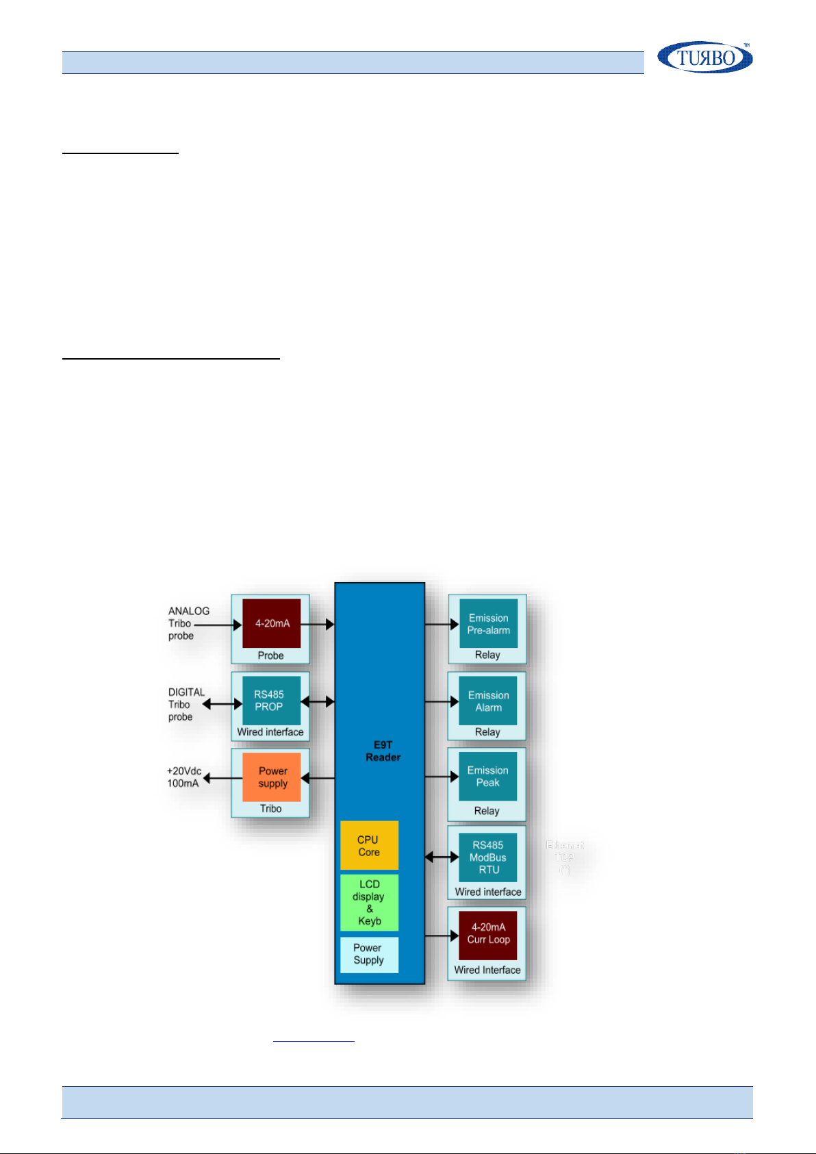
The “E9T triboelectric reader”, also defined like E9T control unit, is a stand-alone electronic device connected to a
triboelectric probe and built for monitoring dust emission in chimneys of industrial systems.
Brief, the dust flowing in a chimney is detected by the triboelectric probe placed in the conduct and connected to
the E9T control unit. The triboelectric probe is able to measure the quantity of emissions flowing and immediately
communicate the measure to the E9T control unit.
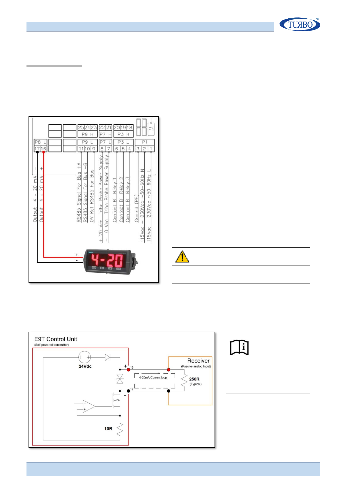
The E9T control unit is provided of LCD graphical display for visualization and local programming and a lot of I/O
lines for system interfacing in order to transmit emissions values and alarms status.
The E9T control unit schematic resources diagram is shown below:
More information are available on Turbo web site

A P P L I C A T I O N N O T E
E 9 T U S A G E I N I N D U S T R I A L F I E L D
A P N t 0 2 6 E 9 T U I F
EN R e v . 1 . 1
T U R B O s . r . l . D u s t F i l t e r C o m p o n e n t s
V i a C e n t r o I n d u s t r i a l e E u r o p e o , 3 3 –T u r a t e ( C O ) I t a l y
T e l + + 3 9 0 3 6 2 5 7 4 0 2 4 F a x + + 3 9 0 3 6 2 5 7 4 0 9 2
3
Control unit wirings
The E9T control unit is provided of a clamp tightening plug connectors to permit all the wirings at the main
system. The connectors are removable and numbered to help wiring operations. Pull carefully the plug
connectors to remove it from the matched male welded on the electronic board.
Wiring operations
1) Remove the lower plastic front panel
to access to the on-board plugs
connectors.
2) Remove the connectors one at time,
carry out the related wiring and
reinsert the connect in the right
positions.
3) Make sure that the wiring has been
carried out correctly.
DANGER
Risk of electric shock
Remove the main power supply before
making any connections to the Control
Unit.

A P P L I C A T I O N N O T E
E 9 T U S A G E I N I N D U S T R I A L F I E L D
A P N t 0 2 6 E 9 T U I F
EN R e v . 1 . 1
T U R B O s . r . l . D u s t F i l t e r C o m p o n e n t s
V i a C e n t r o I n d u s t r i a l e E u r o p e o , 3 3 –T u r a t e ( C O ) I t a l y
T e l + + 3 9 0 3 6 2 5 7 4 0 2 4 F a x + + 3 9 0 3 6 2 5 7 4 0 9 2
4
Terminal list
Ref
Cat
No.
term
Terminal
marking
Description
Main
Power
Input
A
1
2
3
N
L
PE
AC 115-230V 50/60Hz
±10%
8VA(10VA max)
AC/DC 24V ±10%
8W (10W max)
Protective ground terminal
Digital
Output
(B contact
Relay)
B
4
5
6
3B
2B
1B
Contact type:
1 Form A (NO)
Rated Voltage:
250Vac
Rated current:
6A Resistive Load
Max. switching voltage:
400Vac
Breaking max capacity:
1500VA
Power
Output for
Tribo Probe
C
7
8
0V
+20Vdc
+20Vdc output (tolerance ±5%) referred to 0V, maximum 100mA,
short circuit protected
Bus
Communication
Port
D
9
10
11
0V
B(-)
A(+)
Mode:
RS-485 Modbus
RTU
0V=shield
Isolation to control circuit:
None
Maximun nodes:
200
HBM protection:
>±15kV
Line Terminator:
220Ω
Digital
Input 1
E
12
13
Mode:
Free contact (limited at 5mA
@30Vdc)
Transil protection:
36V
Digital
Input 3
E
14
15
Isolation to control circuit:
2,5kV
Analog
Output
E
16
17
+
-
Mode:
Unipolar current mode
Isolation to control circuit:
None
Current range:
4mA to 20mA
Accuracy:
± 32uA/step
Output capability:
20mA @ 500Ω
Digital
Output
(A contact
Relay)
B
18
19
20
3A
2A
1A
Contact type:
1 Form A (NO)
Rated Voltage:
250Vac
Rated current:
6A
Max. switching voltage:
400Vac
Breaking max capacity:
1500VA
Analog
Input
E
21
22
-
+
Mode:
Unipolar current mode
Isolation to control circuit:
None
Current range:
0mA to 20mA
Accuracy:
± 32uA/step
Input impedance:
200Ω
Tribo Probe
(Dig)
Communication
Port
D
23
24
25
0V
B(-)
A(+)
Mode:
RS-485 Bus
0V=shield
Isolation to control circuit:
None
HBM protection:
>±15kV
Line Terminator:
220Ω
Digital
Input 2
E
26
27
Mode:
Free contact (limited at 5mA
@30Vdc)
Transil protection:
36V
Digital
Input 4
E
28
29
Isolation to control circuit:
2,5kV
DANGER
Recommended cable cross-section and length
Risk of electric shock
The input and output terminals, numbered 7
to 17 and 21 to 29, are safety extra low
voltage (SELV) terminals and must only be
connected to low voltage supplies.
Cat
Cross Section
Approvals
Notes
A
0,75mm2
IEC 60227
IEC60245
No-flame cable
B
0,75mm2
No-flame cable
C
0,75mm2
No-flame cable
D
0,75mm2
No-flame cable
E
0,50mm2
No-flame cable
PE
0,75mm2
No-flame cable, Yellow-green

A P P L I C A T I O N N O T E
E 9 T U S A G E I N I N D U S T R I A L F I E L D
A P N t 0 2 6 E 9 T U I F
EN R e v . 1 . 1
T U R B O s . r . l . D u s t F i l t e r C o m p o n e n t s
V i a C e n t r o I n d u s t r i a l e E u r o p e o , 3 3 –T u r a t e ( C O ) I t a l y
T e l + + 3 9 0 3 6 2 5 7 4 0 2 4 F a x + + 3 9 0 3 6 2 5 7 4 0 9 2
5

A P P L I C A T I O N N O T E
E 9 T U S A G E I N I N D U S T R I A L F I E L D
A P N t 0 2 6 E 9 T U I F
EN R e v . 1 . 1
T U R B O s . r . l . D u s t F i l t e r C o m p o n e n t s
V i a C e n t r o I n d u s t r i a l e E u r o p e o , 3 3 –T u r a t e ( C O ) I t a l y
T e l + + 3 9 0 3 6 2 5 7 4 0 2 4 F a x + + 3 9 0 3 6 2 5 7 4 0 9 2
6
Triboelectric probe interfacing
The E9T control unit can interfaces an analog or digital triboelectric probe. The probe is a microprocessor-based
measuring instrument designed to detect and measure dust emissions caused by breaking of bag filters.
The analog triboelectric probe is provided of industrial 4-20mA current-loop isolated output to long distance
transmit the emission value read to an E9T control unit. The current-loop line is more suitable in plant where
there are high peaks noises and electromagnetic disturbances.
The digital triboelectric probe is provided of industrial RS-485 isolated communication port to transmit emission
value read and receive some configuration messages. The communication protocol is proprietary and can only
work with E9T control unit and Eco-Net family devices of Turbo. The digital line is more suitable when fast
response is needed.
The standard Turbo triboelectric probe is provided of both analog and digital interface. Due to different electrical
reference levels of analog and digital outputs, the end-user must connect only in one way, avoiding to connect
both analog and digital at the same time.
Analog probe
The E9T control unit interfacing to analog output of the probe is shown in below schematics.

A P P L I C A T I O N N O T E
E 9 T U S A G E I N I N D U S T R I A L F I E L D
A P N t 0 2 6 E 9 T U I F
EN R e v . 1 . 1
T U R B O s . r . l . D u s t F i l t e r C o m p o n e n t s
V i a C e n t r o I n d u s t r i a l e E u r o p e o , 3 3 –T u r a t e ( C O ) I t a l y
T e l + + 3 9 0 3 6 2 5 7 4 0 2 4 F a x + + 3 9 0 3 6 2 5 7 4 0 9 2
7
In analog probe interfacing, the E9T control unit will provide the power supply to the probe.
It is necessary to connect terminals 7 and 21 together (see JB jumper on the schematic…) to provide a stable
measure reference point.
The J1 jumper of the triboelectric probe is used to set the emission range, only for analog output.
Please see the E9TRB manual for more information.
Digital probe
The E9T control unit interfacing to digital communication port of the probe is shown in below schematics.
The J1 jumper of the triboelectric probe doesn’t take effect for digital probe.
Please see the E9TRB manual for more information.

A P P L I C A T I O N N O T E
E 9 T U S A G E I N I N D U S T R I A L F I E L D
A P N t 0 2 6 E 9 T U I F
EN R e v . 1 . 1
T U R B O s . r . l . D u s t F i l t e r C o m p o n e n t s
V i a C e n t r o I n d u s t r i a l e E u r o p e o , 3 3 –T u r a t e ( C O ) I t a l y
T e l + + 3 9 0 3 6 2 5 7 4 0 2 4 F a x + + 3 9 0 3 6 2 5 7 4 0 9 2
8
Alarm relays
The E9T control unit is provided of three independent relay contacts related to different emission alarm events
(Pre-Alarm, Alarm and Peak). Each time an alarm event is detected, the E9T switches the related relay contact in
order to trigger a load (external relay bobbin, lamp, buzzer, …) to remotely signal the alarm.
The alarm event detections are fully configurable by on-screen menu. Please see the Commissioning section for
programming instructions.
All the relay contacts are voltage free. Please do-not exceed the maximum ratings of the on-board relay contacts
(please see terminals list for more details).
WARNING
It is not possibile to set or exchange the alarm
events in different relays positions than the
factory hardware configuration.
Relay connections
a) Pre-Alarm relay wiring scheme
b) Alarm relay wiring scheme
c) Peak relay wiring scheme
Example of remote acoustic and
visual signaling when in Pre-Alarm
Example of indirect power motor
ON/OFF when in Alarm

A P P L I C A T I O N N O T E
E 9 T U S A G E I N I N D U S T R I A L F I E L D
A P N t 0 2 6 E 9 T U I F
EN R e v . 1 . 1
T U R B O s . r . l . D u s t F i l t e r C o m p o n e n t s
V i a C e n t r o I n d u s t r i a l e E u r o p e o , 3 3 –T u r a t e ( C O ) I t a l y
T e l + + 3 9 0 3 6 2 5 7 4 0 2 4 F a x + + 3 9 0 3 6 2 5 7 4 0 9 2
9
Analog output
The E9T analog output provides a 4-20mA current-Loop with a value proportional to emissions read and
displayed. The analog output transmits the emission value to a passive panel mounted display, PLC or DCS,
remotely placed in a control room.
The 4-20mA current-Loop is a standard in
industrial applications, due to its simplicity of
installation, high immunity to noises and the
possibility to travel long distances with no signal
degrading.
The E9T analog output is classified as ACTIVE
(sourcing power) and an external power source for
current-Loop is not needed.
The output is protected against reverse voltage
polarity, fast voltage transients and maximum
current and it is not galvanically isolated from
control circuit.
WARNING
The output is +24Vdc self-powered. Do not power the
current-loop line by external devices.
Risk of damaging the output port.
Here is an example E9T output current-loop diagram for connection to a remote passive receiver:
Please read the instruction
manual of the Receiver before
connect it to the E9T’s analog
output.

A P P L I C A T I O N N O T E
E 9 T U S A G E I N I N D U S T R I A L F I E L D
A P N t 0 2 6 E 9 T U I F
EN R e v . 1 . 1
T U R B O s . r . l . D u s t F i l t e r C o m p o n e n t s
V i a C e n t r o I n d u s t r i a l e E u r o p e o , 3 3 –T u r a t e ( C O ) I t a l y
T e l + + 3 9 0 3 6 2 5 7 4 0 2 4 F a x + + 3 9 0 3 6 2 5 7 4 0 9 2
10
RS-485 Modbus RTU
The RS-485 Modbus RTU is a serial communication standard for industrial controllers that uses a differential signal
over twisted pair wires to drive digital information at long distances supporting local networks and multidrop
communication.
The RS-485 is used as the physical layer underlying many automation protocols including Modbus.
The Modbus is a serial communication protocol for use with PLC’s and supervisory (RTU, SCADA) systems.
Each device on the network using Modbus is provided of a unique and configurable address.
The E9T control unit supports the RTU format, that makes use of a compact binary representation of the data.
The Modbus physical layer
WARNING
The length and quality of the RS-485 line affect the
quality of the signal. Though the theoretical maximum
length of a RS-485 Bus is 1200 meters for data rates
between 100Baud and 100KBaud.
Requirements of wiring in order to obtain good signal quality:
1) Section min 2 +1 x 0,32mm2(a twisted pair and a single
pole
2) Shielded
3) Twisted pair cables
4) Resistant to UV rays (for outdoor installation only)
5) CAT.5 cable

A P P L I C A T I O N N O T E
E 9 T U S A G E I N I N D U S T R I A L F I E L D
A P N t 0 2 6 E 9 T U I F
EN R e v . 1 . 1
T U R B O s . r . l . D u s t F i l t e r C o m p o n e n t s
V i a C e n t r o I n d u s t r i a l e E u r o p e o , 3 3 –T u r a t e ( C O ) I t a l y
T e l + + 3 9 0 3 6 2 5 7 4 0 2 4 F a x + + 3 9 0 3 6 2 5 7 4 0 9 2
11
The E9T control unit is provided of on-board 220Ω
termination line resistor for RS-485 Bus.
When JP11 jumper (red highlighted) is :
Open : Termination line resistor disconnected
Closed: Termination line resistor connected
Suggested RS-485 cable
Manufacturer
:
Belden
Application
:
Industrial
Product code
:
3106A
Poles
:
Twisted pair + single pole
Shielded
:
YES
Type
:
UV resistant
The Ground Terminal
E9T control unit have a GND (ground) terminal in order to provide a stable voltage reference for RS-485 shielded
cable. If a shielded cable is used for RS-485 connection it must be connected only in one side.
Do not connect the GND terminal to an external device ground !
Modbus communication settings
E9T control unit is provided of a dedicated menu accessible by the local user interface useful to configure the
Modbus communication parameters:
Ref
Item
Parameter
Me a s ure
Unit
Fa ct o ry
de fault
Rang e
M6.1
Address
Set the RS-485 address of the Control Unit
on the network
Address
1
1
255
M6.2
Communication speed
Set the speed of the communication
Baud rate
Baud
9600
9600
38400
M6.3
Parity
Set the parity mode of the byte
Parity
Bit
None
None
Even
M6.4
Stop
Set the number of Stop bits
Stop bit
Bit
1
1
2

A P P L I C A T I O N N O T E
E 9 T U S A G E I N I N D U S T R I A L F I E L D
A P N t 0 2 6 E 9 T U I F
EN R e v . 1 . 1
T U R B O s . r . l . D u s t F i l t e r C o m p o n e n t s
V i a C e n t r o I n d u s t r i a l e E u r o p e o , 3 3 –T u r a t e ( C O ) I t a l y
T e l + + 3 9 0 3 6 2 5 7 4 0 2 4 F a x + + 3 9 0 3 6 2 5 7 4 0 9 2
12
How to choice the right communication Speed
The parasitic capacity of the transmission line increases as the line length increases, thereby limiting the
maximum bus speed. An empirical law provides the following values:
Speed (bps)
Max Length (mt)
Note:
115200
85
A good rule is to respect a minimum distance of 1 meter
between multiple devices connected in the RS-485Bus.
57600
170
38400
250
19200
500
9600
1000
Communicate with the Network
With The E9T control unit placed on the RS-485 ModBus network, the end-user can choice to work with Turbo
“PC-Panel Tribo” dedicated software or develop its own application using ModBus device registers. In the
Network, the E9T is to consider as slave devices.
PC-Panel Tribo Software
Turbo has designed a PC software, named “PC-Panel Tribo” for remote management of the E9T functionalities.
Developed for Windows platforms (WinXP, Win7/8,
Win10), the “PC-Panel Tribo” software provide the
user can interact with the device in order to configure
parameters, read device status, and monitor the
control unit.
Thanks to a well-defined interface, the user can
navigate through the tabs to monitor all the
parameters and also the real-time values. The user
interface is customizable with logo, languages and
displayed information in order to meet all the user
requirements.
Please refers to Turbo Sales dept. to purchase and obtain the
PC-Panel software package and license.
An USB to RS-485 Serial converter cable is sold with “PC-Panel Tribo”
software package. The cable provides a fast, simple way to connect
devices with a RS-485 interface to USB 2.0, supporting data transfer
rate up to 3Mbaud.
The USB-RS-485 drivers, available free from http://www.ftdichip.com,
which are used to make the FT232R in the cable appear as a virtual
COM port (VCP). This then allows the user to communicate with the
USB interface via a standard PC serial emulation port. Another FTDI USB
driver, the D2XX driver, can also be used with application software to
directly access the FT232R on the cable though a DLL.
The RS-485 serial converter is made of some colored cables where:
Color
Terminal
Note:
Orange
RS-485 A (+)
The other terminals must be cut or placed in a separate position on a terminal
block. The above image is showing RS-485 cabling for an EC+ model where the
serial port is placed as previously explained.
Yellow
RS-485 B (-)
Black
Shield

A P P L I C A T I O N N O T E
E 9 T U S A G E I N I N D U S T R I A L F I E L D
A P N t 0 2 6 E 9 T U I F
EN R e v . 1 . 1
T U R B O s . r . l . D u s t F i l t e r C o m p o n e n t s
V i a C e n t r o I n d u s t r i a l e E u r o p e o , 3 3 –T u r a t e ( C O ) I t a l y
T e l + + 3 9 0 3 6 2 5 7 4 0 2 4 F a x + + 3 9 0 3 6 2 5 7 4 0 9 2
13
Modbus RTU protocol & registers
Modbus message
Following the ModBus protocol standard requirements, it is possible to write and read the E9T control unit
registers in order to configure parameters, perform functions and check the device status in real-time operations.
Standard Modbus message for the E9T devices
Device Address
Comprises between 1 and 127. The “0” value is not permitted.
Func ID
Func 03 (Read Holding registers)
Func 06 (Write Single register)
Data
The E9T register (AND value if writing a register) ;
CRC
The cyclic redundancy check is calculated following CRC16 algorithm criteria.
E9T Modbus registers
The complete list of E9T Modbus registers is listed below. In the access column R means that the related register
are read-only and R/W means that the related register can be read and also written.
DEVICE Settings
Item
Register
Access
Default
Note
Device software version
0x0000
R
Software release mounted
Device hardware version
0x0001
R
Hardware version of E9T
Alarm RESET
0x0002
R/W
0
1= force alarm RESET
Buzzer RESET
0x0003
R/W
0
1= force buzzer RESET
Device serial No.
0x000C
R/W
0
Serial number
Device menu language
0X000E
R/W
0
0=ITA, 1=ENG, 2=FR, 3=DE, 4=ESP
Enable/Disable local GUI
0X000F
R/W
0
0=Enabled 1=Disabled
Device ModBus address
0X0060
R/W
1
1÷127
Device Communication speed
0X0061
R/W
2
0=38400 Baud
1=19200 Baud
2= 9600 Baud
Device Communication Parity bit
0X0062
R/W
0
0=No Parity
1=Odd Parity
2=Even Parity
Device Communication Stop bit
0X0063
R/W
1
0=2 Stop bit 1=1 Stop bit
TRIBO Alarms Settings
Item
Register
Access
Default
Note
Pre-Alarm threshold
0x0010
R/W
800
x 0,01 mg/m3
Pre-Alarm Time
0x0011
R/W
300
x 0,5 seconds
Alarm threshold
0x0012
R/W
1500
x 0,01 mg/m3
Alarm Time
0x0013
R/W
60
x 0,5 seconds
Peak threshold
0x0014
R/W
3000
x 0,01 mg/m3
Peak Time
0x0015
R/W
10
x 0,5sec

A P P L I C A T I O N N O T E
E 9 T U S A G E I N I N D U S T R I A L F I E L D
A P N t 0 2 6 E 9 T U I F
EN R e v . 1 . 1
T U R B O s . r . l . D u s t F i l t e r C o m p o n e n t s
V i a C e n t r o I n d u s t r i a l e E u r o p e o , 3 3 –T u r a t e ( C O ) I t a l y
T e l + + 3 9 0 3 6 2 5 7 4 0 2 4 F a x + + 3 9 0 3 6 2 5 7 4 0 9 2
14
Analog TRIBO Settings
Item
Register
Access
Default
Note
Enable/Disable
0x0020
R/W
0
0=Disabled 1=Enabled
Zero Emissions Offset
0x0022
R/W
0
Offset to zeroing the emission
Not calibrated probe mA value
0x0023
R/W
0
x 0,01 mg/m3
Ref. Emissions
0x0024
R/W
1000
microAmpere
Digital TRIBO Settings
Item
Register
Access
Default
Note
Enable/Disable
0x0030
R/W
0
0=Disabled 1=Enabled
Zero Emissions Offset
0x0032
R/W
0
Offset to zeroing the emission
Calibration value K
0x0033
R/W
150
Adjustment coefficient for comparing
Emissions reading filter
0x0034
R/W
8
Filter sentitivity
ALARMS
Item
Register
Access
Default
Note
Enable/disable Hour Count Alarm
0x0040
R/W
0
0=Disabled 1=Enabled
Hour Counter Threshold
0x0041
R/W
0
Hours
Hours from 1st power ON (LSB)
0x0050
R
0
16bit LSB
Hours from 1st power ON (MSB)
0x0051
R
0
16bit MSB
Hidden Parameters
Item
Register
Access
Default
Note
LCD backlight ON time
0x0070
R/W
0
0=Always ON
Relay 1 contact type
0x0071
R/W
1
0=N.open 1=N.Closed
Relay 1 activation mode
0x0072
R/W
0
0=Pulse 1=Latch
Relay 1 activation time
0x0073
R/W
10
seconds
Relay 2 contact type
0x0074
R/W
1
0=N.open 1=N.Closed
Relay 2 activation mode
0x0075
R/W
0
0=Pulse 1=Latch
Relay 2 activation time
0x0076
R/W
10
seconds
Relay 3 contact type
0x0077
R/W
1
0=N.open 1=N.Closed
Relay 3 activation mode
0x0078
R/W
0
0=Pulse 1=Latch
Relay 3 activation time
0x0079
R/W
10
seconds
Enable/Disable Buzzer
0x007A
R/W
0
1=Disabled 0=Enabled
ADC 4mA IN calibration value
0x007B
R/W
120
Factory calibrated. Do not modify !
ADC 20mA IN calibration value
0x007C
R/W
600
Factory calibrated. Do not modify !
DAC 4mA OUT calibration value
0x007D
R/W
520
Factory calibrated. Do not modify !
DAC 20mA OUT calibration value
0x007E
R/W
2600
Factory calibrated. Do not modify !

A P P L I C A T I O N N O T E
E 9 T U S A G E I N I N D U S T R I A L F I E L D
A P N t 0 2 6 E 9 T U I F
EN R e v . 1 . 1
T U R B O s . r . l . D u s t F i l t e r C o m p o n e n t s
V i a C e n t r o I n d u s t r i a l e E u r o p e o , 3 3 –T u r a t e ( C O ) I t a l y
T e l + + 3 9 0 3 6 2 5 7 4 0 2 4 F a x + + 3 9 0 3 6 2 5 7 4 0 9 2
15
Board Parameters
Item
Register
Access
Default
Note
Control Unit Job phase
0x0090
R
0
0=Power ON 2=Running
4=Prog. Parms 7=Prog. S/n
Digital input 1 (note1)
0x0097
R
1
0=Closed 1=Open
Digital input 2 (note1)
0x0098
R
1
0=Closed 1=Open
Digital input 3 (note1)
0x0099
R
1
0=Closed 1=Open
Digital input 4 (note1)
0x009A
R
1
0=Closed 1=Open
State of Relay 1
0x009B
R
1
0=OFF 1=ON
State of Relay 2
0x009C
R
1
0=OFF 1=ON
State of Relay 3
0x009D
R
1
0=OFF 1=ON
State of the Digital Tribo connection
0x009E
R
1
0=Connected 1=Not connected
Alarm presence
0x00A0
R
0
0=No alarm 1=Alarms
Hour counter Alarm
0x00A1
R
0
0=No alarm 1=Alarm
State of Tribo pre-alarm
0x00A2
R
0
0=No alarm 1=Alarm
State of Tribo alarm
0x00A3
R
0
0=No alarm 1=Alarm
State of Tribo peak alarm
0x00A4
R
0
0=No alarm 1=Alarm
Current output from Analog Tribo
0x00B1
R
0
microAmpere
Calculated Emission
0x00B2
R
0
x 0,01 mg/m3 (2.00 on LCD = 200)
(note1) Reserved for future developments.
Local user interface
LCD display & messages
The E9T is provided of a local user interface with a large LCD display and a membrane keyboard.
Please read the E9T user manual for more information about settings. Icons and information are arranged as
shown in the following image:
Icon
Description
Analog Triboelectric probe enabled
Digital Triboelectric probe enabled
RS-485 Modbus communication
Local keyboard locked

A P P L I C A T I O N N O T E
E 9 T U S A G E I N I N D U S T R I A L F I E L D
A P N t 0 2 6 E 9 T U I F
EN R e v . 1 . 1
T U R B O s . r . l . D u s t F i l t e r C o m p o n e n t s
V i a C e n t r o I n d u s t r i a l e E u r o p e o , 3 3 –T u r a t e ( C O ) I t a l y
T e l + + 3 9 0 3 6 2 5 7 4 0 2 4 F a x + + 3 9 0 3 6 2 5 7 4 0 9 2
16
Main screen
Item
Device state
Message displayed
1
Normal state
Emission value expressed in
mg/m3
No Tribo probe
connected
Tribo disabled
2
Normal state
No
Pre-alarm error
event
Tribo 1 (preal) [flashing]
Alarm error event
Tribo 1 (alarm) [flashing]
Peak error event
Tribo 1 (peak) [flashing]
3
Normal state
1 2 3
Pre-alarm error
event
1 [flashing] 2 3
Alarm error event
1 2 [flashing] 3
Peak error event
1 2 3 [flashing]
4
Normal state
Menu page
Sub-menu page
Hide menu page
5
No Tribo probe
connected
No icon
Analog Tribo
enabled
icon fixed when OK
icon flashing if fault
Digital Tribo
enabled
icon fixed when OK
icon flashing if fault
6
No communication
No icon
Communication
running
icon
7
Local keyboard
enabled
No icon
Local keyboard
disabled
icon

A P P L I C A T I O N N O T E
E 9 T U S A G E I N I N D U S T R I A L F I E L D
A P N t 0 2 6 E 9 T U I F
EN R e v . 1 . 1
T U R B O s . r . l . D u s t F i l t e r C o m p o n e n t s
V i a C e n t r o I n d u s t r i a l e E u r o p e o , 3 3 –T u r a t e ( C O ) I t a l y
T e l + + 3 9 0 3 6 2 5 7 4 0 2 4 F a x + + 3 9 0 3 6 2 5 7 4 0 9 2
17
Keyboard functions
Multi-function button
Short press
( <2sec)
-In main window it enters in configuration Menu
-In Menu window it returns to main widow
-In sub-Menu windows it returns to Menu window
-During error it resets the error event on the display
-In serial No. programming menu it saves the serial
-In parameter modification it returns to previous menu
-In hide menu it returns to main window
Multi-function button
Short press
(<2sec)
-In main window it increases the display contrast
-In sub-Menu windows it increases the parameter value
-During error it scrolls the errors on the 2nd row of the
display
-In serial No. programming menu it increases the serial
Multi-function button
Short press
(<2sec)
-In main window it decreases the display contrast
-In parameter modification it decreases the parameter
value
-In sub-Menu windows it enters in parameter
modification
-In serial No. programming menu it decreases the serial
Single function button
Long press 2nd
button and Short
press (<2sec) the
3th button
-In Menu window it enters in the hide menu
Single function button
Short press
(<2sec)
-In Menu window it moves up through the menu items
Long press
(>5sec)
at power-On
-It activates the hidden calibration parameters
Multi-function button
Short press
(<2sec)
-In the main window it enters in language Menu
-In Menu window it moves down through the menu items
Long press
(>5sec)
at power-on
-It enters in serial No. programming menu
Single function button
Long press
(> 5sec)
at power-on
-It reset all parameters values and set factory default
values

A P P L I C A T I O N N O T E
E 9 T U S A G E I N I N D U S T R I A L F I E L D
A P N t 0 2 6 E 9 T U I F
EN R e v . 1 . 1
T U R B O s . r . l . D u s t F i l t e r C o m p o n e n t s
V i a C e n t r o I n d u s t r i a l e E u r o p e o , 3 3 –T u r a t e ( C O ) I t a l y
T e l + + 3 9 0 3 6 2 5 7 4 0 2 4 F a x + + 3 9 0 3 6 2 5 7 4 0 9 2
18
Connect E9T control unit to an external device
When the E9T control unit is part of a complex machine that is controlled through the use of a PC, a PLC or a DCS,
then it is necessary to make the right connections in order to use all the functions it has available.
Depending on the equipment that the complex system makes available and on the specific needs that the
customer requires, the E9T can be connected in several ways, starting from reading only the emission value on a
4-20mA current-loop line up to communicating via ModBus to have full control of the control unit.
Here are some possible usage scenarios, complete with connection diagram.
Remotely read emission values via 4-20mA line
The easy way to remotely read dust emission values measured by the E9T control unit is to connect an external
device provided of 4-20mA current-loop input.
Please read Analog output chapter for more information about wiring connection.
The external device analog input will be configured to read 4-20mA current-loop in PASSIVE mode.
In case the 4-20mA setting is not available, the user will configure the analog input as dc voltage input and place a
250 Ohm 1/2W resistor between input terminals. With this, the user will need to set the measure scale between
1Vdc (4mA) and 5Vdc(20mA) on the external device.
The measurement scale is linear and corresponds to:
Current
loop
Emission
value
Note
4,00mA
0 mg/m3
20,0mA
50 mg/m3
Emission full scale for a standard triboelectric probe.
If an analog triboelectric probe is used, the emission full scale depends on J1 jumper
setting. Please refer to documents relating to the triboelectric probe used.
The external device should be properly programmed to manage the emission value received from E9T control unit
in order to display value and handle alarms.

A P P L I C A T I O N N O T E
E 9 T U S A G E I N I N D U S T R I A L F I E L D
A P N t 0 2 6 E 9 T U I F
EN R e v . 1 . 1
T U R B O s . r . l . D u s t F i l t e r C o m p o n e n t s
V i a C e n t r o I n d u s t r i a l e E u r o p e o , 3 3 –T u r a t e ( C O ) I t a l y
T e l + + 3 9 0 3 6 2 5 7 4 0 2 4 F a x + + 3 9 0 3 6 2 5 7 4 0 9 2
19
Example of PLC connected to E9T 4-20mA output for emission reading by mean of analog channel.

A P P L I C A T I O N N O T E
E 9 T U S A G E I N I N D U S T R I A L F I E L D
A P N t 0 2 6 E 9 T U I F
EN R e v . 1 . 1
T U R B O s . r . l . D u s t F i l t e r C o m p o n e n t s
V i a C e n t r o I n d u s t r i a l e E u r o p e o , 3 3 –T u r a t e ( C O ) I t a l y
T e l + + 3 9 0 3 6 2 5 7 4 0 2 4 F a x + + 3 9 0 3 6 2 5 7 4 0 9 2
20
Remotely handling of E9T alarms
If the external device is not provided of analog inputs, it is possible to program E9T control unit emission alarms
thresholds and then connect its relay contacts to digital inputs of external device.
The external device digital inputs will be configured to read digital status of the relay contacts coming from E9T.
Please read Alarm relays chapter for more information about wiring connection.
The external device should be properly programmed to manage the alarms status received from E9T control unit
in order to display conditions and perform some collateral functions, if needed.
It is also possible to build remotely handling of E9T alarms and remotely read emission by 4-20mA together to
have the best interfacing condition.
In case, the user will need to realize both the connections and perform E9T settings to use more resources at the
same time.
Table of contents
Other Turbo Industrial Equipment manuals
Popular Industrial Equipment manuals by other brands

Maxcess
Maxcess TIDLAND Roll Restorer user manual

Bomar
Bomar Easycut Series operating instructions

Bona
Bona Power Drive AS0003201 installation guide

SCHUNK
SCHUNK PGN Assembly and operating manual

Primera
Primera FX1000 Operator's guide

DCL
DCL MINE-X SOOTFILTER ACCOMPANIMENT TO THE INSTALLATION, OPERATION AND MAINTENANCE MANUAL