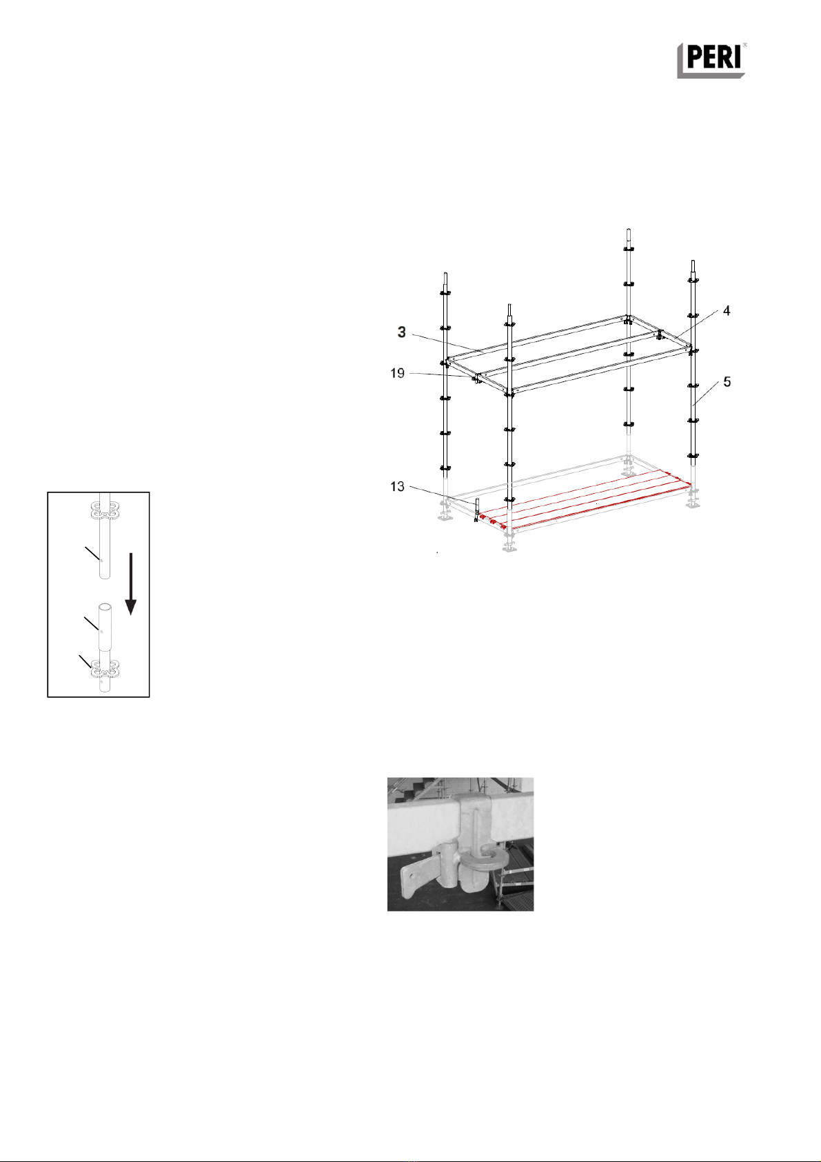
Always begin erecting at the highest
point, preferably at an internal corner.
A1.1 Load distributing base area
recting the scaffold must follow the
sequence described below!
Settlement must be avoided! The
scaffold must onl be erected on
suitable distribution plates on ground
or structure capable of withstanding
all imposed loads!
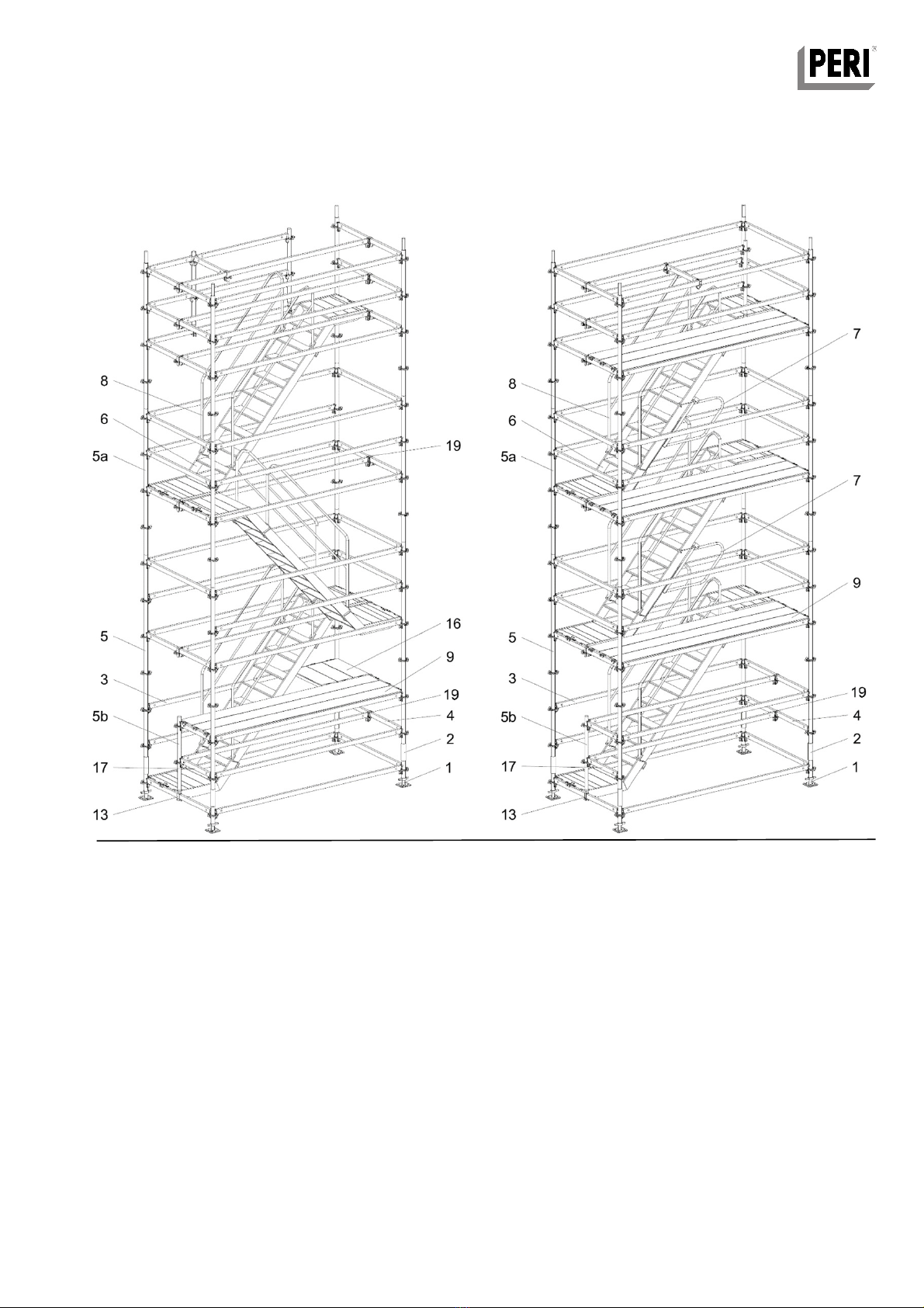
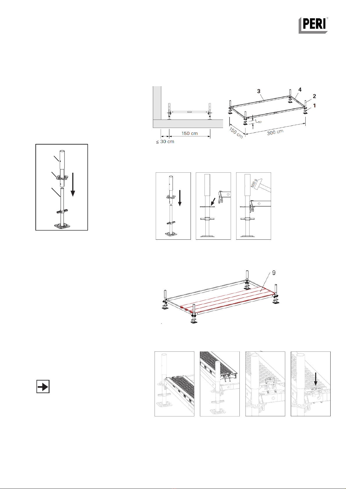
Lay the Ledgers UH 300 (3) and Ledgers
UH 150 (4) down to determine the length of
the surface to be scaffolded. This will fix
the distance between the Adjustable Base
Plates UJB (1)
A1.2 Adjustable Base Plates UJB
Position Adjustable Base Plates (1) at the
ends of the Ledgers UH 300 Plus (3) &
Ledgers UH 150 (4).
A1.3 Changes in base level
Steps, slopes and changes in level can be
accommodated using adjustment of the
Adjustable Base Plates / Base Spindles.
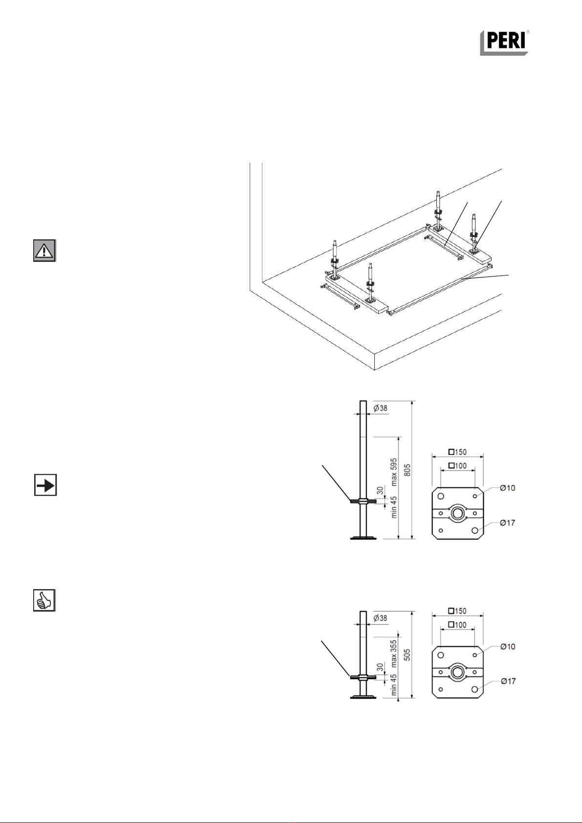
UJB 38-80/55
Yellow handle
Base Spindles TR 38-70/50, without
coloured handles, may be used instead of
Adjustable Base Plates UJB (1). xtension
range = 47mm – 535mm to top of collar
handle.
Adjustable Base Plates UJB 38-50/30 with
red handles have a maximum extension of
355mm to top of collar handle. Adjustable
Base Plates UJB 38-80/55 with yellow
handles have a maximum extension of 595
mm. to top of collar handle. Check with
P RI for suitability of use.
A – Assembly and Dismantling – Alternating
A1 Assembling the base
UJB 38-50/30
Red handle
Fig.A1-2
Fig.A1-3
5
Fig.A1-1
1
3
4
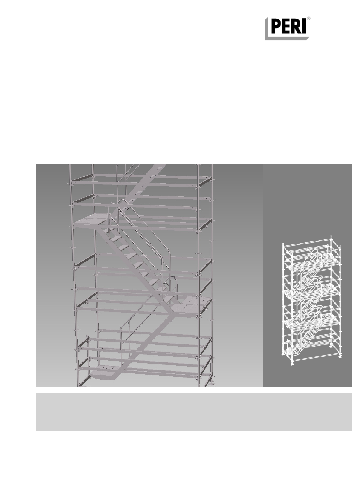
PERI UP Flex Stairs 75
Instructions for Assembly and Dismantling – Short lift system to SG4:15