TERASAKI T2DR25 User manual

Model Applicable products
Number of
poles
T2DR25
E250-N
□
S160-N□, S160-G□, S225-N□, S225-G□
S250-N□, S250-G□
Cannot be applied to electronic breaker (with LCD or Pretrip
alarm)
3P, 4P
T2DR40 E400-N□
S400-C□, S400-N□, S400-G□, S400-P□3P, 4P
T2DR80 S800-C□, S800-N□, S800-R□, S800-P□3P, 4P
Please carefully store this instruction
manual in an easily accessible place.
Instruction Manual
for
Model T2DR25, T2DR40, T2DR80 Draw-out Mechanisms
KRB-5394b

Table of Contents
1.Introduction ······························································································
1
2.Precautions for installation
····················································································2
3.
Precautions for conductor connections and control circuit wiring·······································3
4.Operation procedures
···························································································4
4-1.Drawing out the breaker
from the CONNECTED Position to the ISOLATED position·····································4
4-2.Removing the breaker in the ISOLATED position ·················································5
4-3. Mounting the removed breaker in the ISOLATED position ·····································5
4-4. Inserting the breaker from the ISOLATED position to the CONNECTED position········5
5.
Standard arrangement for plug-in type auxiliary circuit terminals ······························6
6
.Locking···············································································································7
7
.Outline dimensions (T2DR25, T2DR40, T2DR80)·············································· 8-10
KRB-5394b 2

1. Introduction
The model T2DR25, T2DR40, T2DR80 draw-out mechanisms allow the breaker to be locked in
either of two positions: CONNECTED and ISOLATED (see Table 1).
Table 1: Breaker position
Breaker
position Main circuit Auxiliary
circuit Display of position
indicator Remarks
CONNECTED
Connected Connected “CONNECTED”Position during the normal use
ISOLATED Disconnected
Disconnected “DISCONNEC.”
Both the main and auxiliary circuits
are disconnected.
Visual appearance (model T2DR25)
①Mounting
hole
②Position
indicator
③Draw-out
cradle
④Draw-out handle
insertion hole
⑤Preventive lever for
draw-out handle
insertion
⑥Key lock
(optional)
⑧Breaker
securing bolt
⑦Lock plate
KRB-5394b
1

2. Precautions for installation
1. Be sure to attach the draw-out cradle to
the angle using 4 mounting bolts.
Table 2: Mounting bolts dimensions table
For T2DR25
Hexagon bolt
M6
×
20
For T2DR40
Hexagon bolt
M8
×
25
For T2DR80
Hexagon bolt
M12
×
35
2. During the assembly of the switchboard,
spread a cover over the breaker and its
draw-out cradle.
In particular, ensure that the vents of the
arc chutes and the contactor and terminal
on the draw-out cradle are kept free from
electric wire chips, grinding swarf, weld
pieces, and the like.
3. During use (current load), do not block the
vents of the arc chutes.
Provide sufficient insulating distance (arc
space) from the grounding metal plate and
insulating plate that are adjacent to the
vents.
(See "insulating distance from the power
source" indicated in the catalog.)
4. Mount the breaker in a place where it is
not exposed to direct sunlight.
①Mounting hole
Angle
Mounting bolt
③
Draw-out cradle
・
・
・
・
⑨Guide pin
・
⑩
Rail groove
・
KRB-5394b 2

3. Precautions for conductor connections and control circuit wiring
1. For the screw to connect the conductor, be sure
to use a plain washer and a spring waster to
ensure the proper connection.
Otherwise, the screw would be easily loosened,
causing the connection to be burned.
2. To clamp the conductor to be connected, use the
specified torque.
Insufficient clamping would cause overheat or
excessive clamping would cause the screw to be
damaged. Therefore, tighten the screw using the
suitable tool for the screw size.
T2DR25
T2DR40
T2DR80
A
M8
M10
M12
8.8
~
14.7 N
・
m
18.6
~
29.4 N
・
m
32.3
~
51.9 N
・
m
B
≦
22mm
≦
30mm
≦40mm
C
≦
15.5mm
≦
20mm
≦26.5mm
D
9mm
11mm
13mm
E
≦
15.5mm
≦
20mm
≦26.5mm
3. Do not tighten the screw by lubricating it.
This would decrease the friction of the threads,
causing the screw to be easily loosened or
excessively tightened.
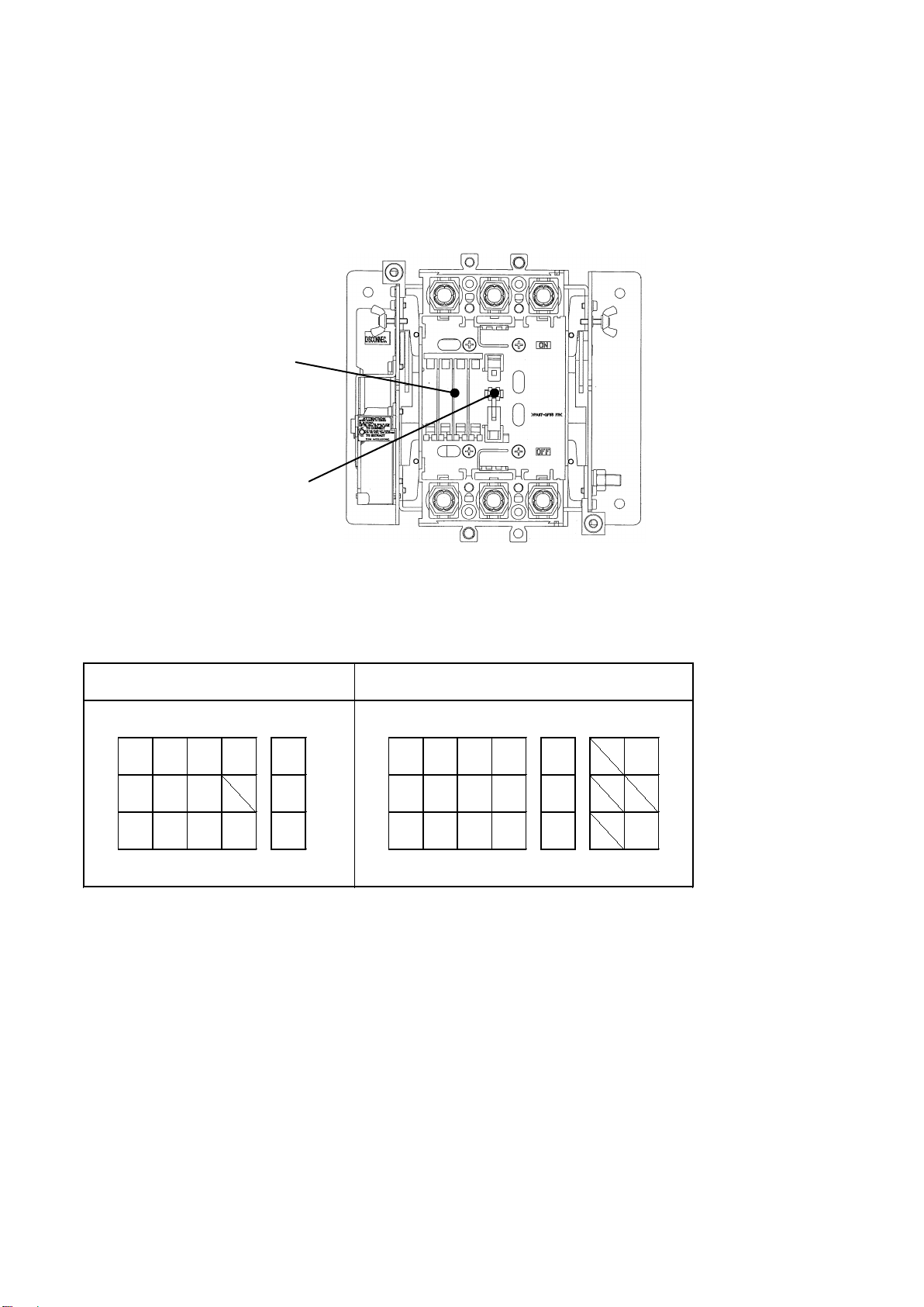
4. Firmly support the connected conductor in a
position near the terminal.
The flow of accidental current will cause large
electromagnetic force to be applied between
the connected conductors.
Against this electromagnetic force, the draw-out
cradle alone is not enough to support the
connected conductors.
・
・
・
③
Draw-out cradle
Insulating support
Connected conductor
Terminal
Plain washer
Spring washer
2 threads or
more
Connected
conductor
・
・
・
・
A
・
・
・
Insulating support
Connected
conductor
Table 3: Terminal detail dimensions table
KRB-5394b
3

5. Do not configure the control circuit between the
input and output of the breaker. This is
dangerous because the circuit still remains
closed even if the breaker is turned OFF.
4. Operation procedures
4-1.Drawing from the CONNECTED position to the ISOLATED position
1)Turn OFF the breaker.
2)⑧Loosen the breaker securing bolts to release the breaker.
3)⑥For the key-lock version, unlock the key lock.
4)⑤Pull down the preventive lever for draw-out handle insertion (toward the load side) and then
insert ⑪draw-out handle into ④draw-out handle insertion hole.
5)⑪When the draw-out handle is slowly turned counterclockwise until it becomes loose, ②
position indicator shows "DISCONNEC."
When ②position indicator shows "DISCONNEC.", the breaker is in the ISOLATED position and
the draw-out handle becomes loose.
Breaker
Incorrect
Breaker
Correct
②
Position
indicator
④
Draw-out handle
insertion hole
⑥
Key lock
⑧Breaker
securing bolt
・
・
・
・
・
・
・
⑤Preventive lever
for draw-out
handle insertion
⑪
Draw-out handle
・
①
Mounting hole
・
KRB-5394b 4

4-2. Removing the breaker in the ISOLATED position
1)Check that the breaker is in the ISOLATED position (②position indicator shows
"DISCONNEC”).
If the breaker is not in the ISOLATED position, see 4.1 to draw out the breaker
to the ISOLATED position.
2)Remove the breaker toward you from the draw-out cradle while raising it.
4-3. Mounting the removed breaker in the ISOLATED position
1)Check that ②position indicator shows "DISCONNEC."
2)Raise the breaker, align ⑨guide pin with ⑩rail groove, and then insert the breaker into the
draw-out cradle.
4-4. Inserting the breaker from the ISOLATED position to the CONNECTED position
1) Pull down ⑤preventive lever for draw-out handle insertion and insert ⑪draw-out handle into
④draw-out handle insertion hole.
2) When ⑪draw-out handle is slowly turned clockwise until it becomes loose, ②position indicator
shows "CONNECTED.”If the breaker is not inserted at max. operating torque, contact us.
Table 4: Draw-out handle operating torque table in case of connection operation
T2DR25
T2DR40
T2DR80
Max. operating torque N
・
m
3 or less
5 or less
7 or less
3) Attach ⑧breaker securing bolt to secure the breaker to the draw-out cradle.
4-5. Contact status of position indicator and position switches(option)
Tables 5 show the contact status of position indicator and position switches respectively.
Refer to Page 6 regards to arrangement position of position switches.
Table 5: Contact statues of position indicator and position switches
Position switch
a-contact (PSa1)
b-contact (PSb1)
Breaker position
Position indicator
CONNECTED
DISCONNEC.
CONNECTED
ISOLATED
KRB-5394b
5

5. Standard arrangement for plug-in type auxiliary circuit terminals
Auxiliary circuit terminals are of self-engaging type.
Tables 6 show auxiliary circuit terminals of internally mounted accessories.
Position switches are mounted by sequence position of Table 6 in draw-out cradle.
"PSa1", "PSb1", "PSc1" are position switches terminals.
T2DR25 draw-out cradle visual appearance
Table6. Arrangement for plug-in type auxiliary circuit terminals (from the front of the draw-out cradle)
Internally mounted accessories
auxiliary circuit terminals
base mounting
Position switches
base mounting
AXa1 AXa2 ALa1 C1 PSa1
AXb1 AXb2 ALb1 PSb1
AXc1 AXc2 ALc1 C2 PSc1
T2DR25
AXa1 AXa2 AXa3 ALa1 PSa1 C1
AXb1 AXb2 AXb3 ALb1 PSb1
AXc1 AXc2 AXc3 ALc1 PSc1 C2
T2DR40, T2DR80
KRB-5394b 6

6. Locking
When the breaker is in the "CONNECTED" position, it can be locked by turning the breaker handle
to the OFF position.
5-1. Lockup with a cylinder key (optional)
Turning the key counterclockwise locks the breaker, while turning it clockwise unlock the
breaker.
Note: To turn the key, depress it at the same time.
5-2. Lockup with a padlock
⑦Up to three padlocks may be used for the lock plate. The padlocks should be supplied by the
customer.
A: 13 mm min.
Diameter:5 to 6.5 mm9
Diameter
A
⑤
Preventive lever
for draw-out
handle insertion
⑦
Lock plate
・
・
KRB-5394b
7


This manual suits for next models
2
Table of contents
Other TERASAKI Industrial Equipment manuals
Popular Industrial Equipment manuals by other brands

Pearson
Pearson CE35-T Case Operation manual

ITOH DENKI
ITOH DENKI POWER MOLLER IB-P03 Technical documentation

ABB
ABB HT563322 Operation manual

RelaDyne
RelaDyne LubriMist DXT Installation and operating manual

LNS
LNS QUICK LOAD SERVO S2 Startup manual

DUSTLESS BLASTING
DUSTLESS BLASTING DB800 MOBILE user manual