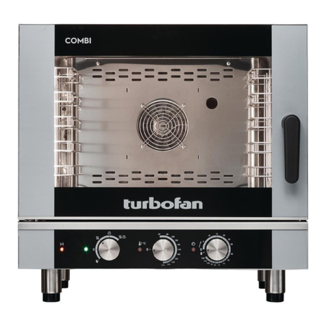
turbofan subway E32SUBC3 User manual

E32SUBC3/C4
OVEN and PROOFER
Amendment 10
E
E32SUBC3/C4
21 January 2015
Service Manual

The reproduction or copying of any part of this manual by any means whatsoever is strictly forbidden unless authorized previously in
writing by the manufacturer.
In line with policy to continually develop and improve its products, Moffat Ltd. reserves the right to change the specifications and
design without prior notice. © Copyright Moffat Ltd. January 2015.
MANUFACTURED BY
Moffat Limited
Rolleston 7675
New Zealand
INTERNATIONAL CONTACTS
AUSTRALIA
Moffat Pty Limited
Web: www.moffat.com.au
E.Mail: [email protected]
Main Office: (tel) +61 (03) 9518 3888
(fax) +61 (03) 9518 3833
Service: (tel): 1800 622 216
Spares: (tel): 1800 337 963
Customer Service: (tel): 1800 335 315
(fax): 1800 350 281
CANADA
Serve Canada
Web: www.servecanada.com
E.Mail: [email protected]
Sales: (tel): 800 551 8795 (Toll Free)
Service: (tel): 800 263 1455 (Toll Free)
NEW ZEALAND
Moffat Limited
Web: www.moffat.co.nz
E.Mail: [email protected]
Main Office: (tel): 0800 663328
UNITED KINGDOM
Blue Seal
Web: www.blue-seal.co.uk
E.Mail: [email protected]
Sales: (tel): +44 121 327 5575
(fax): +44 121 327 9711
Spares: (tel): +44 121 322 6640
(fax): +44 121 327 9201
Service: (tel): +44 121 322 6644
(fax): +44 121 327 6257
UNITED STATES
Moffat
Web: www.moffat.com
Sales: (tel): 800 551 8795 (Toll Free)
(tel): +1 336 661 1556
(fax): +1 336 661 9546
Service: (tel): 800 858 4477 (Toll Free)
(tel): +1 336 661 1556
(fax): +1 336 661 1660
REST OF WORLD
Moffat Limited
Web: www.moffat.co.nz
E.Mail: [email protected]

Contents
1. Specifications..................................................................................... 2
2. Installation ........................................................................................ 3
Before Connection to Power Supply.
Location.
Electrical Connection.
Water Connection.
Before Use.
3. Operation ........................................................................................... 5
Oven Digital Controller Layout.
Proofer Digital Controller Layout.
Oven Operation.
Field Adjustable Settings.
4. Cleaning ........................................................................................... 20
Routine Maintenance.
5. Fault Finding.................................................................................... 21
Oven. - Fault Finding.
Proofer - Fault Finding.
6. Service Procedures ..........................................................................25
6.1 Access
6.2 Oven Replacement
6.3 Proofer Replacement
6.4 Adjustment / Calibration
7. Electrical Schematic & Wiring Diagrams.........................................37
8. Exploded Parts List ..........................................................................41
Appendix 1 Door Reversal....................................................................50
Reference .............................................................................................52
Controller Settings
Fault Codes
ALL INSTALLATION AND SERVICE REPAIR WORK MUST BE CARRIED OUT BY
QUALIFIED PERSONS ONLY.
IMPROPER INSTALLATION, ALTERATION, ADJUSTMENT, MAINTENANCE OR SER-
VICE MAY CAUSE PROPERTY DAMAGE, INJURY OR DEATH
ENSURE SUPPLY IS SWITCHED OFF BEFORE SERVICING
WARNING:

Specifications
2
ELECTRICAL ENTRY
COLD WATER CONNECTION
E
80 min (3.15")
MINIMUM
INSTALLATION
CLEARANCE
810 (31.89")
1774(69.84")
1128(44.41)
735 (28.94")
646(25.43")
111.5 (4.39") 627.5 (24.70")
120(4.72)
50 min (1.97")
MINIMUM
INSTALLATION
CLEARANCE
810 (31.89")
DOOR SWING
565mm (22.24")
* SUPPLIED WITH 2m FLEXIBLE
WATER TUBE AND DOUBLE
CHECK VALVE
REAR VIEW
E32SUBC3/C4 Oven and Proofer

Installation
3
Before Connection to Power Supply
• Remove all packing.
• Check equipment and parts for damage. Report any damage immediately to the carrier and
distributor.
• Remove protective plastic coating from the side panels.
• Check that the available power supply is correct to that shown on the rating plate located on the
right-hand side panel.
380-415 Vac, 50/60 Hz, 3P+N+E, 7.9 kW @ 415V.
208 Vac, 50/60 Hz, 3P+E, 7.9 kW @ 208V.
220-240 Vac, 50/60 Hz, 3P+E, 7.9 kW @ 240V.
Location
• To ensure correct ventilation for the motor and controls the following minimum installation
clearances are to be adhered to:
• Use a spirit level to ensure oven / proofer is level from side to side and front to back. (If this is not
carried out, uneven baking could occur).
CLEARANCE FROM SOURCE OF HEAT.
A minimum distance of 300mm (12”) from appliance sides is required.
NOTE: Fixed installations require at least 500mm - 20” clearance at right hand side of oven
for service access.
Electrical Connection
• E32SUBC3/C4 oven / proofers are supplied fitted with power cords. Ensure unit is fitted with cor-
rect cord and plug.
• To access the electrical connection terminal block, grounding lug and strain relief, remove the
right hand side panel.
Installation Requirements
It is most important that this oven / proofer is installed correctly and that operation is
correct before use.
Installation shall comply with local electrical, health and safety requirements.
Top 200 mm / 8”
Rear 50 mm / 2”
Left-hand side 0 mm / 0”
Right-hand side 80 mm / 3”
Important:
THE VENT LOCATED ON TOP OF THE OVEN MUST NEVER BE OBSTRUCTED.
WARNING - This Appliance Must Be Grounded.

Installation
4
Water Connection
The Oven / Proofer is fitted with a water filtration
system. This system will require the Filter
Cartridge and the Double Check Valve connecting
to the Filter Body. And the filter system connecting
to the mains water supply, Follow the instructions
below to connect up the water filter system.
1. Connect Tube Connection fitted with Double
Check Valve, to the Connector on Filter Body
inlet side.
2. Fit Filter Cartridge to the Filter Body. (¼turn
clockwise bayonet fitting).
3. Connect Double Check Valve to main water
supply connection.
4. Connect up power supply to Prover / Holding
Cabinet and turn ‘On’ the appliance.
5. Turn on the mains water supply and carry out
a leak check of the Prover / Holding Cabinet.
• Max inlet pressure 550kPa / 80psi.
Before Use
• Operate the oven for about 1 hour at normal
operating temperature to remove any fumes or
odours which may be present.
Connected to Inlet
Connection on rear
of Prover / Holding
Cabinet
Filter Body
Connector
Tube Connection
Double Check Valve
Filter
Cartridge
Mains Water
Inlet Pipe c/w
Double Check
Valve.
Proofer Water
Connector
Filter
Body

Operation
5
Display Screen
A full graphical display screen which will display all relevant
information relating to both Oven and Proofer during Operation and
Programming Modes:-
The left hand Screen - Oven:-
Will display all information relating to the oven during
Programming and Operation.
Navigation Keys
Used to change the parameters during the
Programming Mode only.
Used to scan through the oven program’s
selected, during the Baking Mode and to
change menu’s during the Programming Mode.
Program Key ‘P’
Press for 3 seconds to access Program Mode for ov-
en program keys.
Program Indicator:
Will illuminate when Program Mode is selected.
Oven Keys
Oven Temp Check Key:
Press to check oven Set and Actual
temperature at any time.
Oven Program Keys (Keys 1 to 5):
All keys will illuminate when in Program Mode until
program required is selected.
Used to select oven program during baking and
oven programming (LED ON).
Used for adding programming and system entry pass-
words.
Used to cancel program’s on completion.
(Press and hold for 2 seconds to cancel
program).
Oven + 1 Minute Key:
Used to increase the baking time in one
minute increments.
Oven On / Off Key:
Turns the Oven only, ‘On’ / ‘Off’.
Description
of
Controls OVEN - Digital Controller Layout

Operation
6
Display Screen
A full graphical display screen which will display all
relevant information relating to both Oven and Proofer
during Operation and Programming Modes:-
The right hand Screen - Proofer:-
Will display all information relating to the Proofer during Pro-
gramming and Operation.
Navigation Keys
Used to change parameters during
Programming Mode only.
Used to scan through the proofer program’s selected,
during the Proofing Mode and to change menu’s dur-
ing programming mode.
Program Key ‘P’
Press for 3 seconds to access change of Proofer tem-
perature and humidity settings.
Also accesses Programming Mode for proofer timer
keys.
Program Indicator:
Will illuminate when Program Mode selected.
Proofer Keys
Proofer Temp / Humidity Check Key:
Press to check proofer set, actual
temperature and humidity at any time.
Proofer Timer Keys:
All keys will illuminate when in Program Mode until
program required is selected.
Used to select proofer timer during proofing (LED ON).
Used to add programming and system entry pass-
words.
Used to cancel timer when proofing complete.
(Press and hold for 2 seconds to cancel timer).
Proofer + 1 Minute Key:
Press to increase the proofing time in one
minute increments.
Proofer On / Off Key:
Turns the Proofer only, On / Off.
PROOFER - Digital Controller Layout

Operation
7
Oven Operation (Flow Chart)
OVEN READY
LOAD OVEN
START
– Press program key
BAKE PROGRAM DONE
UNLOAD OVEN
CANCEL ALARM
– Press program key
SELECT DIFFERENT PROGRAM
Press desired program key e.g.
TEMP STATUS
OR
OVEN READY
TURN ON / PREHEAT
Press ON / OFF key,
oven will pre-heat to
Programme # 1
LOAD OVEN
START
– Press program key
BAKE PROGRAM DONE
UNLOAD OVEN
CANCEL ALARM
– Press program key

Operation
8
3.3 Field Adjustable Settings
Press the Programming Key ‘P’ for 3 seconds to access the Service Menu.
The programming light ‘Prog’ will illuminate.
The display screen will show the following service menu settings:-
1. Proofer Settings.
2. Recipe.
3. System.
4. Service.
5. Exit.
Use the ‘Up’ / ‘Down’ scroll keys to scroll through the service menu settings, and press
the programming key ‘P’ to access.
Enter password by sequentially pressing keys as per below:-
1. Proofer settings No password required
2. Recipe settings Oven#1, oven#1, oven#2, oven#4
3. System settings Oven#1, proofer#2, oven#1, oven#2
4. Service settings Proofer#2, oven#3, prooder#2, proofer#3
Proofer settings (refer 3.3.1)
Setting Range Default Setting
Temp C 38-42C 40C
Humidity % 80-85C 80C
Cooldown timer 0-60mins 0
Recipe Settings (refer 3.3.2 / 3.3.3)
Proofer Program Keys Default Time Setting
Proofer #1 60min
Proofer #2 60min
Proofer #3 60min
Proofer #4 60min
Proofer #5 60min
Oven Program Keys Time Setting Temp Setting
(example only actual program may differ)
Oven #1 Bread 12mins 177C
Oven #2 Cookies 11mins 163C
Oven #3 Bread 14mins 163C
Oven #4 Bread 14mins 177C
Oven #5 Bread 10mins 177C
System Settings (refer 3.3.4)
Setting range Default Setting
Temp display C or F C
Oven beeper tone 1-9 3
Proofer beeper tone 1-9 5
Beeper volume 1-4 2
Humidity Offset -30 to + 30 % 0
Humidity Sampling Interval 0-120secs 30sec
Water tank max temp 35-50C 46C
Water tank min temp 35-50C 39C
Operation
9
Service Settings (refer 3.3.5 / 3.3.6 / 3.3.7)
Temperature Offset Setting range Default Setting
Temp offset oven probe +/-11C -3C
Temp offset prover air probe +/-11C -2C
Temp offset prover water probe +/-11C 0C
Diagnostic
Oven probe temp displays current probe reading
Proofer probe air temp displays current probe reading
Proofer probe water temp displays current probe reading
Door switch Open/Close displays door switch status
Float switch Open/Close displays water tank float switch status
Humidity probe reading displays current probe humidity reading
Oven heat relay output status displays ON or OFF status
Oven power ON relay output status displays ON or OFF status
Proofer heat relay output status displays ON or OFF status
Proofer water heater relay output status displays ON or OFF status
Proofer power ON relay output status displays ON or OFF status
Oven fan relay output status displays ON or OFF status
Counters
Relay cycles - oven heater
Relay cycles - proofer air heater
Relay cycles - proofer water heater
Error counter - oven probe
Error counter - oven hi temp
Error counter - proofer air probe
Error counter - proofer air hi temp
Error counter - humidity sensor
Error counter - proofer water probe
Error counter - proofer water hi temp
Error counter - proofer water low

Operation
10
3.3.1
Proofer Adjustable Settings
The following Proofer settings are adjustable by the operator:-
Press the Programming Key ‘P’ for 3 seconds to access the Service Menu.
The programming light ‘Prog’ will illuminate.
The display screen will show the following service menu settings:-
1. Proofer Settings.
2. Recipe.
3. System.
4. Service.
5. Exit.
Use the ‘Up’ / ‘Down’ scroll keys to scroll through the service menu settings.
Select No.1. ‘Proofer Settings’ and press the Programming Key ‘P’, the Proofer
Temperature Setting screen will display.
Temperature Settings.
Range - 38˚C to 42˚C.
Factory Default = 40˚C.
Press either ‘Left’ or ‘Right’ keys to scroll through the temperature adjustment settings
to the temperature required and press the Programming Key ‘P’ to save the change.
The Proofer Humidity Setting screen will display.
Humidity Settings.
Range - 80% to 90% in increments of 5%.
Factory Default = 80%.
Press either ‘Left’ or ‘Right’ keys to scroll through the humidity adjustment settings to
the required setting and press the Programming Key ‘P’ to save the change and return
to the Service Menu.
Scroll down to the ‘Exit’ menu and press the Programming Key ‘P’ to exit the Service
Menu. The programming light ‘Prog’ will go out.
NOTE: The following Menu’s are Password Protected and are only accessible by the
authorized Service Agents:-
2. Recipe.
3. System.
4. Service.
Should the Store Operator require to change settings in these areas, the Service Agent
should be contacted.

Operation
11
3.3.2 Oven Recipes
The following Oven Recipe settings are adjustable by the Authorised Service Agents:-
Press the Programming Key ‘P’ for 3 seconds to access the Service Menu. The
programming light ‘Prog’ will illuminate.
The display screen will show the following service menu settings:-
1. Proofer Settings.
2. Recipe.
3. System.
4. Service.
5. Exit.
Use the ‘Up’ / ‘Down’ scroll keys to scroll through the service menu settings.
Select No.2. ‘Recipe Settings’ and press the Programming Key ‘P’,
Press the Oven # 1 key, Oven # 1 key, Oven # 2 key, Oven # 4 key, then press
Programming Key ‘P’
Recipe Programming Setting screen will display.
Press an oven programme key
The Oven Recipe # Time Setting screen will display
Time Settings.
Range - 00:00 to 99:59
Factory Default = 14:00
Press either ‘Left’ or ‘Right’ keys to scroll through the time adjustment settings to the
time required and press the Programming Key ‘P’ to save the change.
The Oven Recipe # Temperature Setting screen will display.
Temperature Settings.
Range - 60˚C to 260˚C.
Factory Default = 177˚C (for bread).
Press either ‘Left’ or ‘Right’ keys to scroll through the temperature adjustment settings
to the temperature required and press the Programming Key ‘P’ to save the change.
The Oven Recipe # Cool down Setting screen will display.
After the cool down time has elapsed an alarm will sound and the bread can then
be put into the bread bins.
Cool down Time Settings.
Range - 00:00 to 99:59
Factory Default = 00:00
Press either ‘Left’ or ‘Right’ keys to scroll through the cool down adjustment settings to
the required setting and press the Programming Key ‘P’ to save the change and return
to the Service Menu.
Scroll down to the ‘Exit’ menu and press the Programming Key ‘P’ to exit the Service
Menu. The programming light ‘Prog’ will go out.

Operation
12
3.3.3 Proofer Recipes
The following Proofer Recipe settings are adjustable by the Authorised Service Agents:-
Press the Programming Key ‘P’ for 3 seconds to access the Service Menu. The
programming light ‘Prog’ will illuminate.
The display screen will show the following service menu settings:-
1. Proofer Settings.
2. Recipe.
3. System.
4. Service.
5. Exit.
Use the ‘Up’ / ‘Down’ scroll keys to scroll through the service menu settings.
Select No.2. ‘Recipe Settings’ and press the Programming Key ‘P’,
Press the Oven # 1 key, Oven # 1 key, Oven # 2 key, Oven # 4 key, then press Pro-
gramming Key ‘P’
Recipe Programming Setting screen will display.
Press a Proofer programme key
The Proofer Recipe # Time Setting screen will display
Time Settings.
Range - 00:00 to 99:59
Factory Default = 60:00
Press either ‘Left’ or ‘Right’ keys to scroll through the time adjustment settings to the
time required and press the Programming Key ‘P’ to save the change.
The Proofer Recipe # Alarm Time Setting screen will display.
Alarm Time Settings.
Range - 00:00 to 59:59.
Factory Default = 40:00
Press either ‘Left’ or ‘Right’ keys to scroll through the temperature adjustment settings
to the temperature required and press the Programming Key ‘P’ to save the change and
return to the Service Menu.
Scroll down to the ‘Exit’ menu and press the Programming Key ‘P’ to exit the Service
Menu. The programming light ‘Prog’ will go out.

Operation
13
3.3.4 System
The following System settings are adjustable by the Authorised Service Agents:-
Press the Programming Key ‘P’ for 3 seconds to access the Service Menu.
The programming light ‘Prog’ will illuminate.
The display screen will show the following service menu settings:-
1. Proofer Settings.
2. Recipe.
3. System.
4. Service.
5. Exit.
Use the ‘Up’ / ‘Down’ scroll keys to scroll through the service menu settings.
Select No.3. ‘System Settings’ and press the Programming Key ‘P’,
Press the Oven # 1, Proofer # 2, Oven # 1, Oven # 2, then press Programming Key ‘P’
System Temp Unit Setting screen will display.
Temp Unit Settings.
Range - ˚C or ˚F
Factory Default = ˚C
Press either ‘Left’ or ‘Right’ keys to scroll between the ˚C or ˚F settings and press the
Programming Key ‘P’ to save the change.
The System Oven Beeper Tone Setting screen will display
Oven Beeper Tone Settings.
Range - 1 to 8.
Factory Default = 3
Press either ‘Left’ or ‘Right’ keys to scroll through the Beeper Tone settings and press
the Programming Key ‘P’ to save the change
The System Proofer Beeper Tone Setting screen will display.
Proofer
Beeper Tone Settings.
Range - 1 to 8.
Factory Default = 5
Press either ‘Left’ or ‘Right’ keys to scroll through the Beeper Tone settings and press
the Programming Key ‘P’ to save the change
The System Beeper Volume Setting screen will display.
System Beeper Volume Settings.
Range - 1 to 4.
Factory Default = 2

Operation
14
3.3.4 System (con’t)
System Beeper Volume Settings. (cont’d)
Press either ‘Left’ or ‘Right’ keys to scroll through the Beeper Volume settings and press
the Programming Key ‘P’ to save the change.
The Humidity Offset Setting screen will display
Humidity Offset Settings.
Range - -30% to + 30%.
Factory Default = +0%
Press either ‘Left’ or ‘Right’ keys to scroll through the Humidity Offset settings and
press the Programming Key ‘P’ to save the change
The Humidity Sampling Interval Setting screen will display.
Humidity Sampling Interval Settings.
Range - 0 to 120 Secs.
Factory Default = 30
Press either ‘Left’ or ‘Right’ keys to scroll through the Humidity Sampling Interval set-
tings and press the Programming Key ‘P’ to save the change
The Water Tank Maximum Temperature Setting screen will display.
Water Tank Maximum Temperature Settings.
Range - 35 to 50oC.
Factory Default = 46oC
Press either ‘Left’ or ‘Right’ keys to scroll through the Water Tank Maximum Tempera-
ture settings and press the Programming Key ‘P’ to save the change
The Water Tank Minimum Temperature Setting screen will display
Water Tank Minimum Temperature Settings.
Range - 35 to 50oC.
Factory Default = 39oC
Press either ‘Left’ or ‘Right’ keys to scroll through the Water Tank Minimum Tempera-
ture adjustment settings to the temperature required and press the Programming Key
‘P’ to save the change and return to the Service Menu.
Scroll down to the ‘Exit’ menu and press the Programming Key ‘P’ to exit the Service
Menu. The programming light ‘Prog’ will go out.

Operation
15
3.3.5 Service Temperature Offset
The following Service Settings are adjustable by the Authorised Service Agents:-
Press the Programming Key ‘P’ for 3 seconds to access the Service Menu.
The programming light ‘Prog’ will illuminate.
The display screen will show the following service menu settings:-
1. Proofer Settings.
2. Recipe.
3. System.
4. Service.
5. Exit.
Use the ‘Up’ / ‘Down’ scroll keys to scroll through the service menu settings.
Select No.4. ‘Service Settings’ and press the Programming Key ‘P’,
Press the Proofer # 2, Oven # 3, Proofer # 2, Proofer # 3 keys, then press Program-
ming Key ‘P’ Service Setting screen will display.
Use the ‘Up’ / ‘Down’ scroll keys to scroll through the service menu settings. Press the
Programming Key ‘P’ to select ‘Temp offset’.
The Temperature Offset for the Oven Probe Setting screen will display
Temperature Offset Settings.
Range - -11oC to + 11oC.
Factory Default = -3oC
Press either ‘Left’ or ‘Right’ keys to scroll through the Temperature Offset settings and
press the Programming Key ‘P’ to save the change
The Temperature Offset for the Proofer Air Probe Setting screen will display
Temperature Offset Settings.
Range - -11oC to + 11oC.
Factory Default = -2oC
Press either ‘Left’ or ‘Right’ keys to scroll through the Temperature Offset settings and
press the Programming Key ‘P’ to save the change
The Temperature Offset for the Proofer Water Probe Setting screen will display.
Temperature Offset Settings.
Range - -11oC to + 11oC
Factory Default = 0oC
Press either ‘Left’ or ‘Right’ keys to scroll through the Temperature Offset settings and
press the Programming Key ‘P’ to save the change

Operation
16
3.3.6 Service Diagnostic
The following Service Settings are adjustable by the Authorised Service Agents:-
Press the Programming Key ‘P’ for 3 seconds to access the Service Menu.
The programming light ‘Prog’ will illuminate.
The display screen will show the following service menu settings:-
1. Proofer Settings.
2. Recipe.
3. System.
4. Service.
5. Exit.
Use the ‘Up’ / ‘Down’ scroll keys to scroll through the service menu settings.
Select No.4. ‘Service Settings’ and press the Programming Key ‘P’,
Press the Proofer # 2, Oven # 3, Proofer # 2, Proofer # 3 keys, then press Program-
ming Key ‘P’ Service Setting screen will display.
Use the ‘Up’ / ‘Down’ scroll keys to scroll through the service menu settings. Press the
Programming Key ‘P’ to select ‘Diagnostic’.
The temperature reading for the Oven Probe screen will display
Use the ‘Up’ / ‘Down’ scroll keys to scroll through the service menu.
The temperature reading for the Proofer Air Probe screen will display
The temperature reading for the Proofer Water Probe screen will display.
The status of the oven door microswitch will display.
The status of the proofer water tank float switch will display.

Operation
17
3.3.6 Service Diagnostic (con’t)
The following Service Settings are adjustable by the Authorised Service Agents:-
Use the ‘Up’ / ‘Down’ scroll keys to scroll through the service menu
The reading for the Proofer Humidity screen will display
The following menu options allow for the switching of the 24Vdc output relays. The
output can be turned on by holding the right side temp key down, it will turn off when
key is released.
The Oven Heater Relay Output screen will display.
Turning on operates only the 24Vdc relay and not the element contactor
The Oven Power Relay Output screen will display.
Turning on operates the 24Vdc relay and turns on the lights.
The Proofer Air Heater Relay Output screen will display.
Turning on operates only the 24Vdc relay and not the element.
The Proofer Water Heater Relay Output screen will display.
Turning on operates only the 24Vdc relay and not the element.
The Proofer Water Heater Relay Output screen will display.
Turning on operates the 24Vdc relay and turns on the lights and fan.
The Oven Fan Relay Output screen will display.
Turning on operates the 24Vdc relay and not the fan.
The next screen tests the pixels in the display and LED’s on the Control Panel.

Operation
18
3.3.7 Service Counters
The following Service Settings are adjustable by the Authorised Service Agents:-
Press the Programming Key ‘P’ for 3 seconds to access the Service Menu.
The programming light ‘Prog’ will illuminate.
The display screen will show the following service menu settings:-
1. Proofer Settings.
2. Recipe.
3. System.
4. Service.
5. Exit.
Use the ‘Up’ / ‘Down’ scroll keys to scroll through the service menu settings.
Select No.4. ‘Service Settings’ and press the Programming Key ‘P’,
Press the Proofer # 2, Oven # 3, Proofer # 2, Proofer # 3 keys, then press Program-
ming Key ‘P’ Service Setting screen will display.
Use the ‘Up’ / ‘Down’ scroll keys to scroll through the service menu settings. Press the
Programming Key ‘P’ to select ‘Counters’.
The Count for the number of times the Oven Element relay has operated screen will
display
Use the ‘Up’ / ‘Down’ scroll keys to scroll through the Counters menu.
The Count for the number of times the Proofer Air Heating Element has operated
screen will display
The Count for the number of times the Proofer Water Heater Element has operated
screen will display.
The Count for the number of times the Oven Temperature Probe has failed (open/
closed circuit or out of range) screen will display.
This manual suits for next models
1
Table of contents
Other turbofan Oven manuals

turbofan
turbofan E85 Prover User manual

turbofan
turbofan EC40 Series Manual

turbofan
turbofan E32D4 User manual

turbofan
turbofan E32D5 User manual

turbofan
turbofan E30M3 User manual

turbofan
turbofan EC40D5 User manual

turbofan
turbofan 30D Series E31D4 User manual

turbofan
turbofan E23D3 User manual

turbofan
turbofan PM Series User manual

turbofan
turbofan E20D Series User manual