Turbovex TX 75A User manual

TURBOVEX TX 75A
Installation, operation and maintenance manual
Revision 2013.06.13

2
Table of contents
General information .............................................................................................................................3
Preface..............................................................................................................................................3
Areas of use......................................................................................................................................3
Incorrect use.....................................................................................................................................3
Deliverables .....................................................................................................................................3
Optional extras .................................................................................................................................3
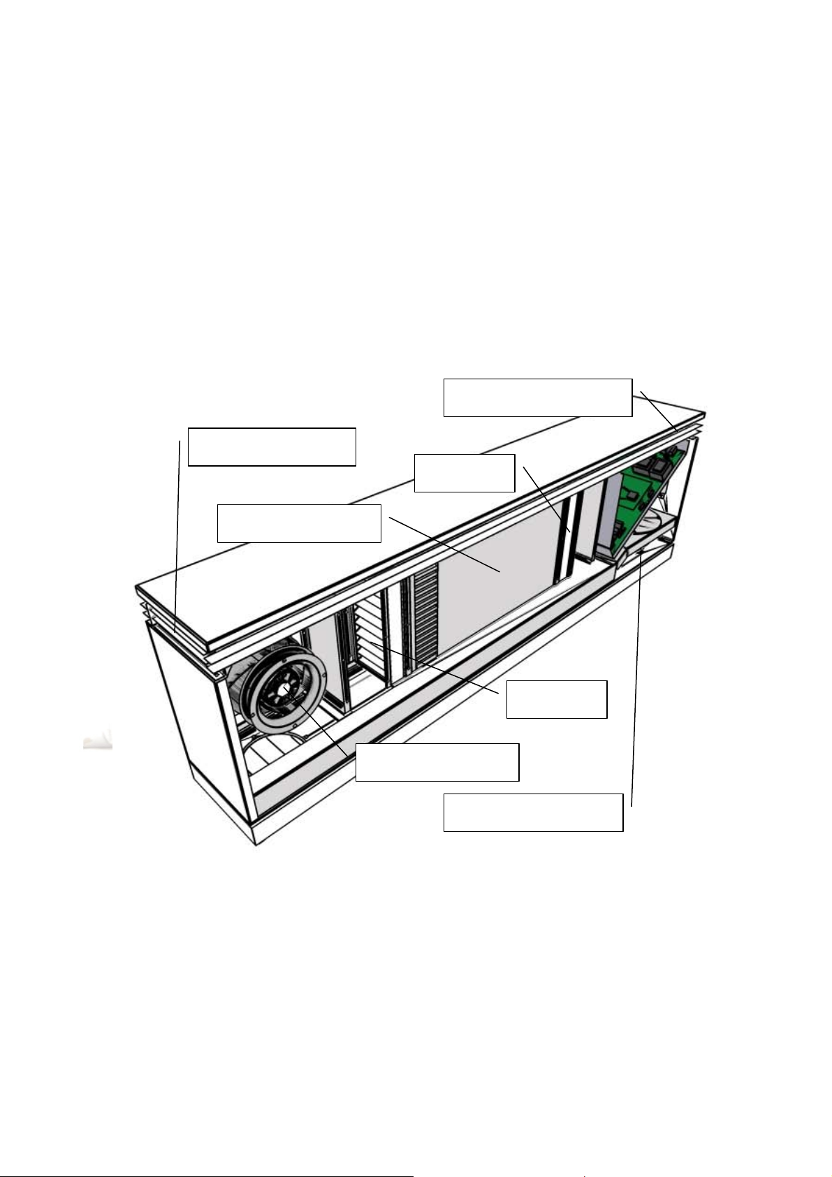
Function principle ............................................................................................................................4
Installation............................................................................................................................................5
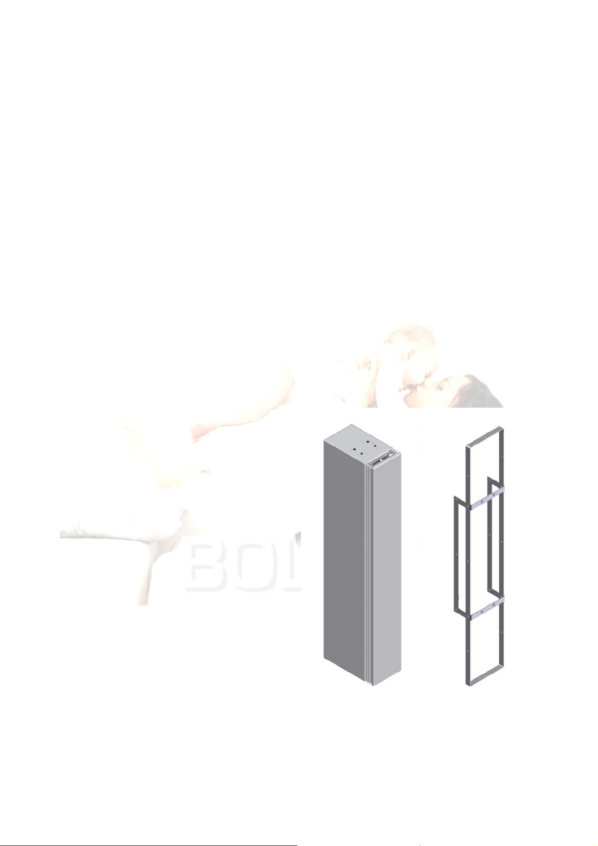
Dimensioned drawing ......................................................................................................................5
External measurements ................................................................................................................5
Mounting frame external measurements......................................................................................5
Placing..............................................................................................................................................6
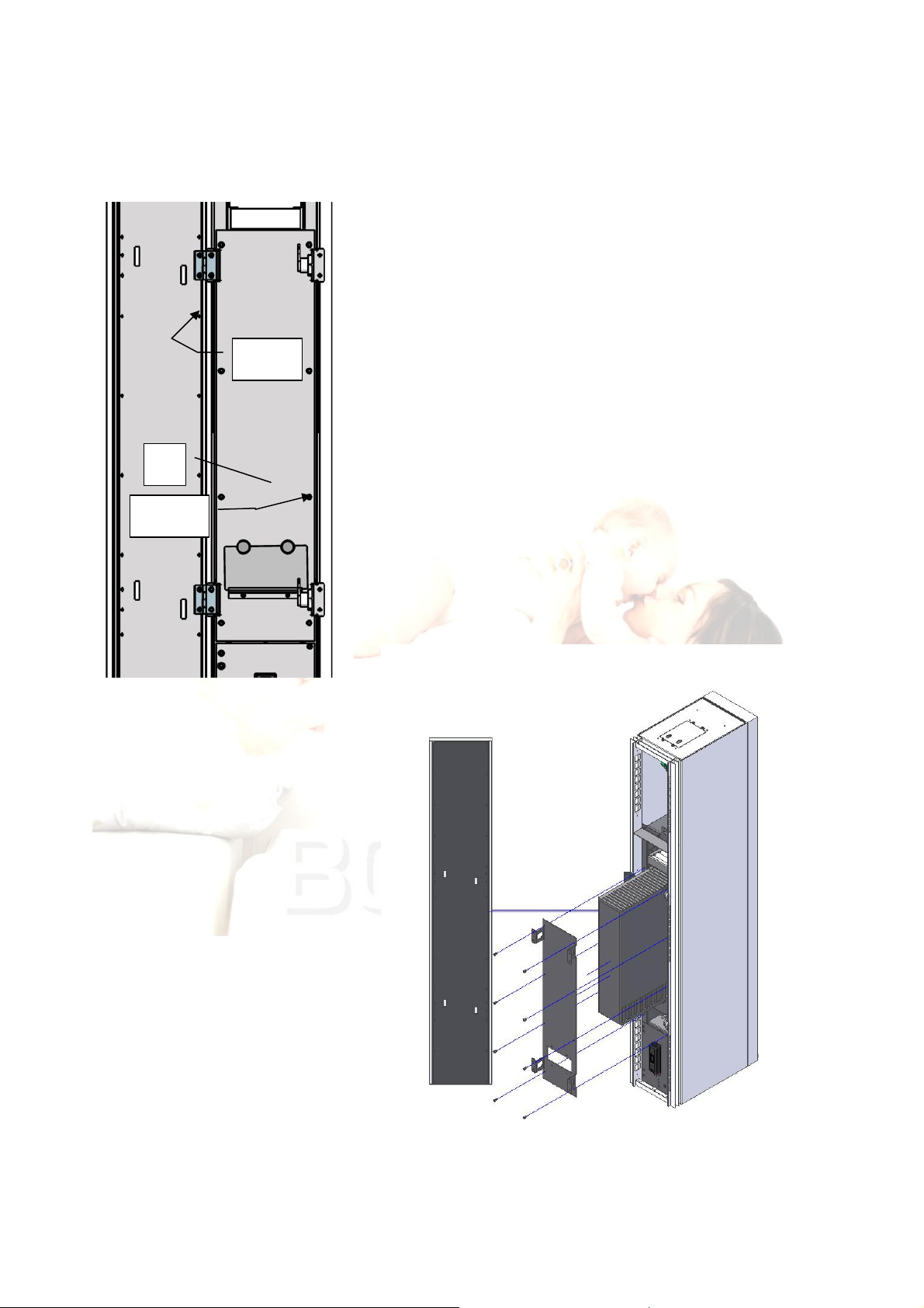
Installation on wall/window.............................................................................................................6
Window installation diagrams for TX-75A .................................................................................7
Service..................................................................................................................................................8
Changing filter .................................................................................................................................8
Cleaning the heat exchanger ............................................................................................................9
Mains connection ...............................................................................................................................10
Retrofitting a TX controller ...............................................................................................................11
Technical specifications.....................................................................................................................12
EU Declaration of Compliance ..........................................................................................................13

3
General information
Preface
This manual contains technical data and information on installation, operation and maintenance.
Areas of use
TX 75A is a decentral ventilation unit for heat recycling in homes, which can be installed on a
window or wall.
Incorrect use
•The window models are not designed for point extraction, and are therefore not suitable for
this purpose.
•The unit is not fitted with a condensate pump or drain, and should not be used in humid
environments, such as bathrooms.
Deliverables
•Ventilation unit including TX control system
Mounting components:
•Mounting frame
•4 x M6 machine screws
Optional extras
•TX controller (control panel)
•CO2sensor
•PIR sensor (movement sensor)
•Facade grille

4
Function principle
The unit is designed to change the air in a room to ensure a better indoor climate. The TX 75A has
two fans which blow the same amount of air in as is extracted via a heat exchanger. The heat
exchanger is designed to heat cold outdoor air by transferring the heat from extracted air to the
intake air, reducing heat loss by approx. 85%. The heat exchanger can also be used to cool intake
air if the outdoor temperature is higher than the room temperature.
The air volume can be adjusted using a CO2sensor (optional extra) to ensure the level of air change
is in line with activity in the room.
Figure 1 - Function principle
Outdoor air is sucked in by the intake motor and blown through the intake filter. The air then passes
through the heat exchanger and out via the intake grille into the room.
Room air is sucked out by the extraction motor through the extraction grille. It is then blown
through the filter and heat exchanger into the open air.
Extraction grille
Intake grille
Extraction motor
Heat exchanger
Filter
Intake motor
Filter

5
Installation
Dimensioned drawing
External measurements
Figure 2 - External dimensions in mm
Mounting frame external measurements
Figure 3 - Mounting frame external dimensions in mm

6
Placing
The unit is usually placed on the wall by a window, with the
extraction grille near the ceiling. This position makes the
most of the coanda effect, which circulates fresh air well into
the room. This gives the air longer to mix with the existing
air in the room, avoiding drafts.
Installation on wall/window
Reinforcement according to local building regulations is
required between the unit and window, which permits the
window to be retained by min. 3 frame fixing screws. The
hole in which the unit is fitted must be minimum 200 mm
wide and 1210 mm high to take the mounting frame.
The mounting frame supplied is
attached to the reinforcement and wall,
or between two reinforcements (if the
unit is placed between two windows)
using suitable screws.
Connect the unit to mains electricity,
and fit it in the mounting frame using
the M6 machine screws supplied. The
holes are located by the unit air filter
the lowest behind the filter cover.
Finish off by sealing around the unit.
Refer to the sealant compound
manufacturer's instructions.
Mounting screws

7
Window installation diagrams for TX-75A

8
Service
Changing filter
We recommend changing the filter and cleaning the heat
exchanger once or twice per year. Remember to disconnect from
the mains before opening the front.
Open the front using a 6 mm Allen key (1). The locks are located
behind two holes in the side, and can be unlocked by turning the
Allen key anticlockwise, and locked by turning it clockwise.
The extraction filter (2) is easily accessible when the
cover is opened. Pull out the filter and replace with a
new one.
If the following is printed on the filter:
"Staubluftseite/Dust Air Side", the text should face away
from the heat exchanger. If there is no printed text, the
filter cannot be fitted the wrong way round.
To remove the intake filter, unscrew the two finger
screws (3). The cover (4) can now be removed and
filter taken out.
Ensure the filter is inserted correctly when replacing
with a new one. The side which must face away from
the heat exchanger (downwards according to the figure)
has the following printed text: "Staubluftseite/Dust Air
Side". If there is no printed text, the filter cannot be
fitted the wrong way round.
Replace the cover and tighten the finger screws.
1
2
3
4

9
Cleaning the heat exchanger
Requires two people!
Start by removing the door by slackening the 4 screws (1)
securing the hinges. One person should support the door and
the other remove the screws. This method avoids damaging
the hinges.
To remove the heat exchanger, remove the cover (2). To do
so, remove the 8 screws (3) with a Philips screwdriver.
When the heat exchanger is out, clean it carefully with a
vacuum cleaner.
Reassemble the unit after cleaning. Ensure the heat exchanger
is correctly positioned. The visible ribs on the sides must face
downwards and to the right, and upwards and to the left
respectively.
1 (x4)
2
3 (x8)

10
Mains connection
Connect Turbovex TX 75A to 230V AC mains electricity at the terminal clamp fitted behind the
cover on the end of the unit. Remove the cover by removing the four screws (M3 x 10 mm). Pass
the cable through the middle cable grommet in the cover, and connect the three wires to Phase,
Neutral and PE.
NB – Mains connection must only be performed by an authorised
electrician!

11
Retrofitting a TX controller
A TX controller can be
retrofitted to a TX 75A inside the
unit, such that the control panel
is always accessible without
having to mount it on the outside
of the wall.
The controller is fitted in the
holder located under the lower
cover. The cover is retained by 4
screws, one in each corner. The
holder can be removed by
unscrewing the 4 middle screws.
Secure the controller to the holder using 2 screws from the back.
The cable can be shortened if necessary. Note wire colours and their positions to ensure correct re-
installation. Pass the cable through the rubber grommet in the cover and through the cable holders
along the inside of the unit on the left – and fit the SUB-D socket in the socket on the partition plate
at the top of the unit.
Screw the holder securely onto the cover, which is then fitted in the unit.
If the unit has a CO2sensor fitted, secure it again using the screw in the bottom right corner.

12
Technical specifications
*Integration measurements for TX 75A including mounting frame are 200 x 241 x 1210 mm.
TX 75A
Dimensions:
WxDxH (mm) 180 x 336 x 1200*
Capacit
(m3/h) 75
Weight (kg)
Filter class F5
Standb
Operation
A
Operation
B Forced
Noise level
(dB(A)) - 30 35 47
Flow (m3/h) - 50 75 135
Energ
consumption
(W)
7.6 13 17 51
cos(φ) 0.55 0.5 0.5 0.5
SEL (J/m3) - 936 838 1360
Temperature
efficienc (%) 88.1

13
EU Declaration of Compliance
Manufacturer:
Name: Turbovex A/S
Address: Industrivej 45
DK-9600 Aars
Country: Denmark
Tel: + 45 96 98 14 62
Dealer:
Name: Turbovex A/S
Address: Industrivej 45
DK-9600 Aars
Country: Denmark
Tel: + 45 96 98 14 62
hereby declares that
Product:
Name: Turbovex TX 75A
Type: Comfort ventilation
complies with
Council Directive of 17 May 2006 on harmonisation of member state legislation on electrical materiel intended for use within certain
voltage ranges (2006/42/EC)
has been manufactured in accordance with the following national standards. which implement a harmonised standard:
DS/EN ISO 12100:2011
Safety of machinery - General principles for design - Risk assessment and risk reduction
DS/EN 60269-1/A1:2009
Low voltage fuses – Part 1: General requirements (IEC 60269-1-1998) supplement A1:2005 to
DS/EN ISO 13857:2008
Safety of machinery - Safety distances to prevent hazard zones being reached by upper and lower limbs
DS/EN ISO -1:2007
Electromagnetic compatibility (EMC) Part 6-1: Generic standards, Immunity for residential, commercial and light-industrial environments
DS/EN ISO -3:2007
Electromagnetic compatibility (EMC) Part 6-3: Generic standards - Emission standard for residential, commercial and light-industrial
environments
DS/EN ISO -4:2007
Electromagnetic compatibility (EMC) Part 6-4: Generic standards, Emission standard for industrial environments
Aars 14 May 2012
Location Date: Marine Engineer Jan H. Møller
Table of contents
Other Turbovex Fan manuals
Popular Fan manuals by other brands

Home Decorators Collection
Home Decorators Collection 56052 Use and care guide

Lennox
Lennox EDA INSTALLATION, SETUP AND USER GUIDE

Home Decorators Collection
Home Decorators Collection 44-WWD Use and care guide

Kruger
Kruger KCE Series General instructions

Harbor Breeze
Harbor Breeze MONTCLAIR E-CM54RBZ5CRCI installation guide

izzy
izzy IZ-9022 instruction manual