Tuxedo MR6K-48X Parts list manual

MR6K-48X
Mid-Rise Scissor Lift
6,000 lbs.
ASSEMBLY & O ERATION
INSTRUCTION MANUAL
November 2014

5
Important!
Be sure to read the operating instructions before operating your lift!
Getting Ready
Make sure you have made all necessary measurements to assure that
your lift will fit in your shop / garage and accommodate the car you intend to lift
with it. Make sure you have enough clearance at the top, and enough width to
allow walking around. And make sure he knows what the circuit requirements are
(110 volt, single phase, 15 amp).

6
Fig.1
Make sure you have someone to help you. The piece of this lift is big, heavy, and
cumbersome. The lift package weighs about 900 pounds by itself. It is possible
for one people to install this lift if he has the appropriate lifting and handling
equipment, but it is definitely easier and faster if there is another people available
to help manhandle the piece into place. As with any activities involving big heavy
materials, safety must be uppermost in your mind. This lift is not difficult to install
because of its simple design, but this very design makes it extremely effective for
shop and residential garage use. With proper preparation and installation, you
will be very pleased with this lift.

7
Required Tools
1. Fork Lift to unload lift on delivery
2. Wrenches and socket with ratchet
3. Adjustable wrench
4. Pliers
5. Flat blade screwdriver
Installation
You will need common hand tools that most homeowners have, like a hammer,
screwdrivers and pliers, but in addition, you will need some tools that are not
common. Each installation is somewhat different, and depends on how much
room you have to work around the lift. Here is a chronological sequence of
installation steps, with the associated tools.
1 Unloading the lift
You’ll need a forklift that can handle about 2000 to 2300 pounds and operate on
a smooth surface.
2 Un-banding the lift
The steel bands which secure the lift parts to the pallets are heavy duty. You’ll
need a pair of metal shears or tin snips to cut the bands. Be very careful when
doing this because the bands will tend to fly apart when they are cut, and the
heavy lift parts may shift when freed from the bands. Stand to the side of the
bands when you cut them, and use gloves when removing the cut bands
because they have sharp edges.
3. Moving pieces
You can move the large piece to the garage with the forklift. Other smaller pieces
can be moved manually.

8
STEP 1--- Assemble the dolly & cable handle
Take out the pieces of the dolly from the carton. Then
assemble them to be the dolly as Fig. 2. Then mount
on the lock-release cable handle on the dolly. ( Fig.3)
Fig.3 Fig.2
STEP 2 --- Mount on the motor pump
Take out the motor pump from the carton also. Then use the bolts provided to fix
the pump on the dolly.(Fig.4)
Fig.4 Fig.5
STEP3 --- Hose connecting & filling the tank
Connect the hydraulic hose to the pump output port. (Fig. 5 )
Then fill the thank with hydraulic oil AW32# or AW46# about 6 L.

9
STEP4 --- AC power supply
Connect the motor pump with proper cable extension and a plug which fit the AC
power supply port on the wall. And please remember there must be one 30A
air-relay in the line for safety
Fig. 6
STEP5 ---Testing
Push the start button on the motor pump to drive the hydraulic oil into the
cylinders on the lift. The lift will rise up with lock latch passing the ladder.
Release the button, the motor will stop rising. Press down the lowering lever on
the pump, the lift will lower down and be lock at the height.
Push the start button 2-3 seconds to rise the frame a little. The safety latch will
leave the cave of safety ladder. Then hold tight the lock-release handle to pull up
the latch through the cable. While holding the handle, press down the lowering
lever again, the lift will lower down to ground.
Note:
If the latch does touch the ladder while
rising or does not leave the ladder after
handle is hold tight, please adjust the
position of the nut on the threaded part.
(Fig. 7)
If everything is OK, now the lift is ready
for operation.
Fig. 7

10
OPERATING INSTRUCTIONS
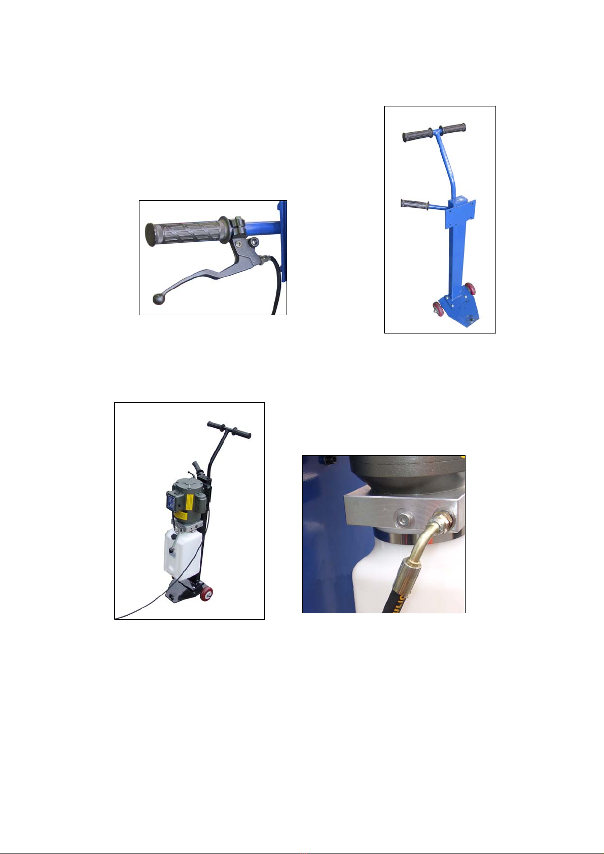
The lift is very simple to operate. The start button on the motor pump is pushed
in and held to activate the switch which turns the electric motor on. The motor
operates an internal pump that forces hydraulic oil into the lift cylinders, which
extends the pistons and raises the lift. As the lift rises, an safety latch will pass
over the steel stops (rectangular blocks on the bar inside of the middle tube),
and you will hear “clanks” as it does so. This sound is normal, and indicates
that the safety latch is passing over the stops properly. The lift is raised to the
desired height by holding the button in while it is rising, and releasing the
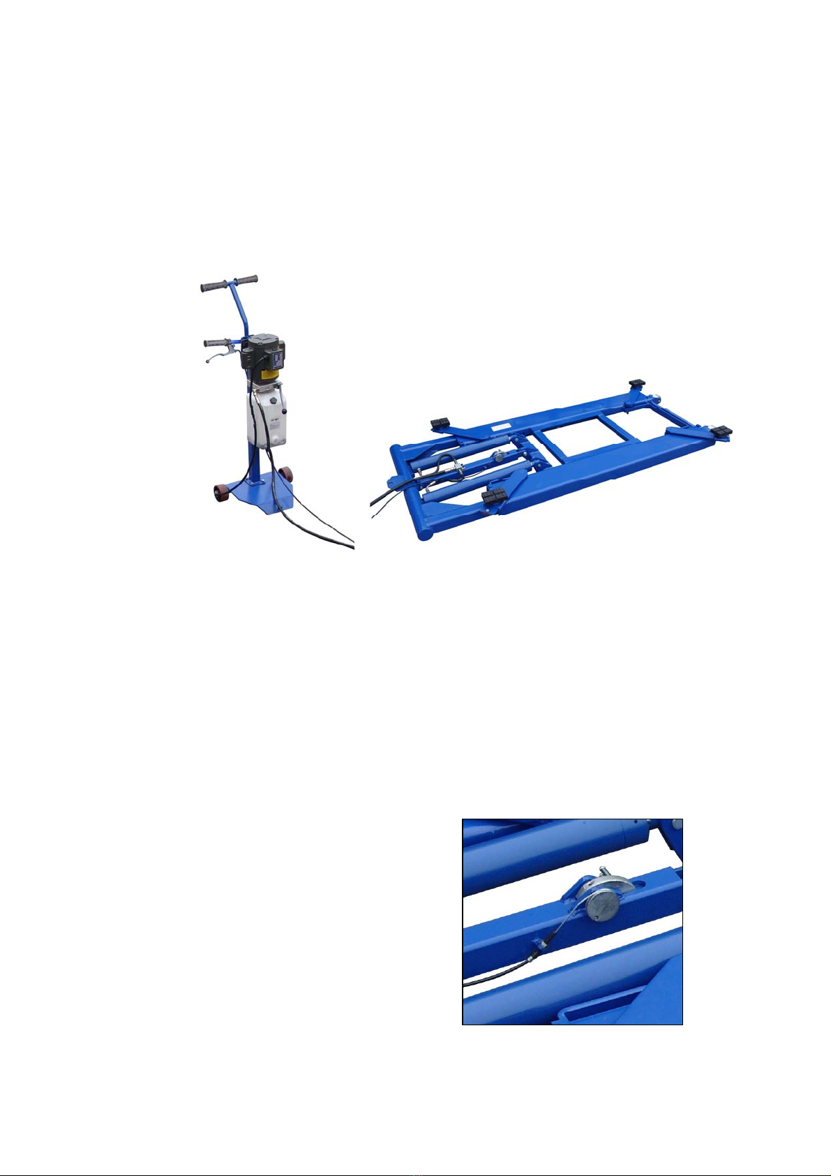
button when the lift has reached its desired position. To lower the lift, you need
to depress the start button again for a few seconds. The lift will “bump”
upwards a little to let the safety latch lock open. If the lock-release cable handle
is hold tight and the lowering lever is press down also, then the weight of the
vehicle will cause the lift to lower by gravity. No power is required to apply to
the motor pump in lowering, but the safety latch must be disengaged to allow
the lift to lower past the stops.
After the installation is complete, raise the lift about two feet high and then
lower it. Repeat this process two or three times, and then top off the hydraulic
oil reservoir again, if necessary. This assures that hydraulic oil is distributed
everywhere in the system that it needs to be.
NOTE: Only top off the reservoir with the lift in the “down” position. If you
fill the reservoir in the “up” position and then lower the lift, there will be too
much hydraulic oil in the system, and it will squirt out of the top of the
control unit.
RAISING A VEHICLE
Drive the vehicle onto the lift frame until it is about centered. Set the parking
brake. Move out the arms to make the rubber pad under the support position
of the vehicle frame. Depress the “up” button to raise the vehicle a little.
Check again all the arms to make sure everything is in safe. Then lift up the
vehicle to desired height.
BE CAREFUL NOT TO RAISE THE VEHICLE SO HIGH THAT IT STRIKES
THE CEILING! MAKE SURE ANTENNAS ARE REMOVED, IF NECESSARY,
AND BE AWARE OF ANYTHING THAT PROTRUDES FROM THE CEILING,
LIKE LIGHTBULBS, GARAGE DOOR OPENERS OR DOOR TRACKS.

11
Fig. 8
MISCELLANEOUS
The hydraulic oil should be replaced every two years, and the inside corners of
the lift arms should be re-greased with a general-purpose axle grease every year,
or so, as it becomes obvious that it needs it.

12
PARTS DRAWING MR6K-48X /161202X (Fig. 9)

13
ITEM CODE DESCRIPTION QUANTITY
1B-x 161202X-B-01 Table 1
2B 161202X-B-02 Retaining ring 2
3B 161202X-B-03 Locking nut 1
4B 161202X-B-04 Oil pipe connector 3
5B 161202X-B-05 Branch inlet pipe 2
6B 161202X-B-06 Oil pipe connector 2
7B 161202X-B-07 Oil supply fitting 1
8B 161202X-B-08 Nut 4
9B 161202X-B-09 Washer 4
10B 161202X-B-10 Break steal cable 1
11B 161202X-B-11 Handle 1
12B 161202X-B-12 Hex screw 4
13B 161202X-B-13 Lock–release handle 1
14B 161202X-B-14 Bolt 4
15B 161202X-B-15 Transmission holder 1
16B 161202X-B-16 Rubber cap 1
17B 161202X-B-17 Oil pipe connector 1
18B 161202X-B-18 General inlet pipe 1
19B 161202X-B-19 Check valve 2
20B 161202X-B-20 Safety locking pin 1
21B 161202X-B-21 Retaining ring 6
23B 161202X-B-23 Scissor pin 2
24B 161202X-B-24 Scissor outside 1
25B 161202X-B-25 Scissor inside 1
26B 161202X-B-26 Wheel pin 2
27B 161202X-B-27 Big wheel 2
28B 161202X-B-28 Small wheel 2
29B 161202X-B-29 Wheel pin 2
30B 161202X-B-30 Connection pin 2
31B 161202X-B-31 Cylinder pin 2
32B 161202X-B-32 Safety locking pin 1
33B 161202X-B-33 Bolt 1
34B 161202X-B-34 Nut 1
35B 161202X-B-35 Cylinder assembly 2
36B 161202X-B-36 Safety locking assembly 1
37B-x 161202X-B-37 cotter pin 2
38B 161202X-B-38 Saddle holder 4
39B-x 161202X-B-39 Rubber saddle 4
40B 161202X-B-40 Locking nut 4
41B 161202X-B-41 Washer 4
42B-x 161202X-B-42 Plate 4
43B 161202X-B-43 Bolt 4
44B-x 161202X-B-44 cotter pin 2
45B 161202X-B-45 Wheel 2
46B 161202X-B-46 Nut 2
47B-x 161202X-B-47 threaded pin 2

14
PARTS DRAWING MR6K-48X /161202X (Fig.10)

15
ITEM CODE DESCRIPTION QUANTITY
1C 161202X-C-01 Pin 1
2C 161202X-C-02 Spring 1
3C 161202X-C-03 Lock block 1
4C 161202X-C-04 Lock pole 3
5C 161202X-C-05 Lock wheel 1
6C 161202X-C-06 Nut 1
7C 161202X-C-07 Bolt 1
8C 161202X-C-08 Steel wire cable 1
9C 161202X-C-09 Lock sheath 1
10C 161202X-C-10 Washer 1
11C 161202X-C-11 Bolt 1
12C 161202X-C-12 Check valve 1

1905 N Main St Suite C, Cleburne, TX 76033
Ph 817-558-9337 Fax 817-558-9740
TUXEDO DISTRIBUTORS LIMITED WARRANTY
Structural Warranty:
The following parts and structural components carry a five year warranty:
Columns Top Rail Beam Uprights Arms Swivel Pins
Legs Carriages Tracks Overhead BeamCross Rails
Limited One-Year Warranty:
Tuxedo Distributors, LLC (“Tuxedo”) offers a limited one-year warranty to the original purchaser of
Tuxedo lifts and Wheel Service in the United States and Canada. Tuxedo will replace, without charge, any
part found defective in materials or workmanship under normal use, for a period of one year after purchase.
The purchaser is responsible for all shipping charges. This warranty does not apply to equipment that has
been improperly installed or altered or that has not been operated or maintained according to specifications.
Other Limitations:
This warranty does not cover:
1. Parts needed for normal maintenance
2. Wear parts, including but not limited to cables, slider blocks, chains, rubber pads and pulleys
3. Replacement of lift and tire changer cylinders after the first 30 days. A seal kit and installation
instructions will be sent for repairs thereafter.
4. On-site labor
Upon receipt, the customer must visually inspect the equipment for any potential freight damage before
signing clear on the shipping receipt. Freight damage is not considered a warranty issue and therefore must
be noted for any potential recovery with the shipping company.
The customer is required to notify Tuxedo of any missing parts within 72 hours. Timely notification must
be received to be covered under warranty.
Tuxedo will replace any defective part under warranty at no charge as soon as such parts become available
from the manufacturer. No guarantee is given as to the immediate availability of replacement parts.
Tuxedo reserves the right to make improvements and/or design changes to its lifts without any obligation
to previously sold, assembled or fabricated equipment.
There is no other express warranty on the Tuxedo lifts and this warranty is exclusive of and in lieu of all
other warranties, expressed or implied, including all warranties of merchantability and fitness for a
particular purpose.
To the fullest extent allowed by law, Tuxedo shall not be liable for loss of use, cost of cover, lost profits,
inconvenience, lost time, commercial loss or other incidental or consequential damages.
This Limited Warranty is granted to the original purchaser only and is not transferable or
assignable.
Some states do not allow exclusion or limitation of consequential damages or how long an
implied warranty lasts, so the above limitations and exclusions may not apply. This warranty
gives you specific legal rights and you may have other rights, which may vary from state to state.

IMPORTANT
POWER UNIT PRIMING PROCEDURE
THE PROBLEM: Power unit runs fine but will not pump any fluid.
Step 1 –Locate the check valve, the flush plug to the left of the lowering valve.
(See drawing below.)
Step 2 –Using an Allen wrench and shop towel –with shop towel in place to catch
fluid –loosen the check valve plug 2 ½ turns to allow it to leak.
Step 3 –Push the START button for one second, then release for three seconds.
Repeat these steps until unit starts pumping fluid.
Step 4 –Tighten the check valve plug.
YOUR POWER UNIT SHOULD BE PRIMED
Other manuals for MR6K-48X
1
Table of contents
Other Tuxedo Scissor Lift manuals
Popular Scissor Lift manuals by other brands

MAHA
MAHA TWIN F III 4.0 operating instructions

TLS
TLS TLSS14ALOR installation manual

Oshkosh Corporation
Oshkosh Corporation JLG ES2632 Operation and safety manual

Challenger Lifts
Challenger Lifts DX77R-LF Installation, operation & maintenance manual

Terex
Terex Genie GS-4655 Operator's manual

Atlas
Atlas TD6MR Installation & operation manual

fetra
fetra 6831 Operation manual

Ravaglioli
Ravaglioli RAV540U Translation of the original instructions

Elevated Access
Elevated Access Sinoboom GTJZ1412 Maintenance manual

POP UP
POP UP EIGER 500 instruction manual

POP UP
POP UP IQ LIFT PRO10 MAINTENANCE & TROUBLESHOOTING HANDBOOK

Kleton
Kleton MJ524 instruction manual