TW Audio VERARF600i User manual

Assembly
Instructions
VERA RF600i

VERA RF600i Assembly Instructions
2
Introduction
Thank you for choosing a high-quality product “MADEIN GERMANY” from TW AUDiO.
The VERA RF600i rigging frame is an accessory for the VERA20i, VERA S17i and
VERA S32i loudspeakers.
This accessory set is characterized by a subtle look, a remarkable size to weight ratio and
ease of use.
If you lend your product to another party, inform that party of the safety-related operating pro-
cedures and hand over this assembly guide. If you require additional copies of this manual,
you can obtain them free of charge from TWAUDiO or download them from www.twaudio.de
Instructions in this setup manual
Strictly adhere to the instructions contained in this assembly guide that are marked as follows:
This symbol in combination with the signal word “Caution” identifies a potentially hazardous
situation. Failure to comply with this safety instruction can lead to light or moderate injury.
This symbol in combination with the signal word “Note” identifies a potentially hazardous
situation. Failure to comply with this safety instruction can lead to product damage.
This symbol in combination with the signal word “Tip” identifies additional information or
notes that will simplify working with TWAUDiO products on the basis of practical experience.
This symbol in combination with the signal word “Warning” identifies a potentially hazardous
situation. Failure to comply with this safety instruction can lead to serious injury or even death.
WARNING
CAUTION
NOTE
TIP

VERA RF600i Assembly Instructions
3
Notes on the products
Read manual
before use!
Before using the rigging frame, carefully read the assembly instructions and keep the instruc-
tions in a safe place together with the VERA RF600i rigging frame.
General information
Assembly Instructions: AM-VERA RF600i
Version 1.4 d, 08/2020
© by TW AUDiO 2020; all rights reserved.
All information contained in this assembly guide was correct to the best of our knowledge at
the time of printing.
Quality warranties or assurance of suitability for a certain type of use based on the technical
specifications, dimensions and weights are not granted by TWAUDiO.
TW AUDiO also shall not assume liability for any secondary damage (property damage and/
or personal injury) nor for the failure to comply with this assembly guide!
TW AUDiO reserves the right to update this document based on recent developments.
TW AUDiO GmbH
Osterholzallee 140
71636 Ludwigsburg
Germany
Phone: + 49 (0) 71 41-48 89 89 0
Fax: + 49 (0) 71 41-48 89 89 99
WWW: www.twaudio.de

VERA RF600i Assembly Instructions
4
Content
1. Safety | Intended use...................................................................................................... 5
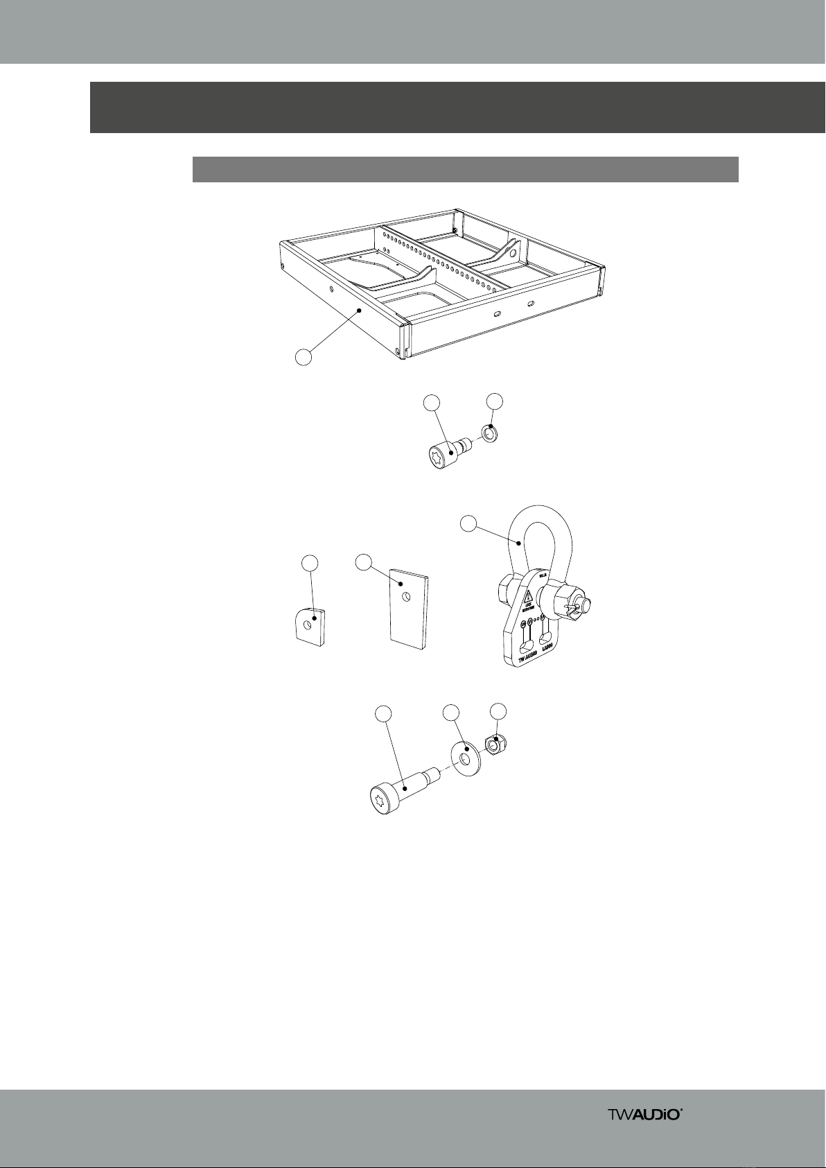
2. Overview ........................................................................................................................ 7
2.1 Scope of delivery..................................................................................................... 7
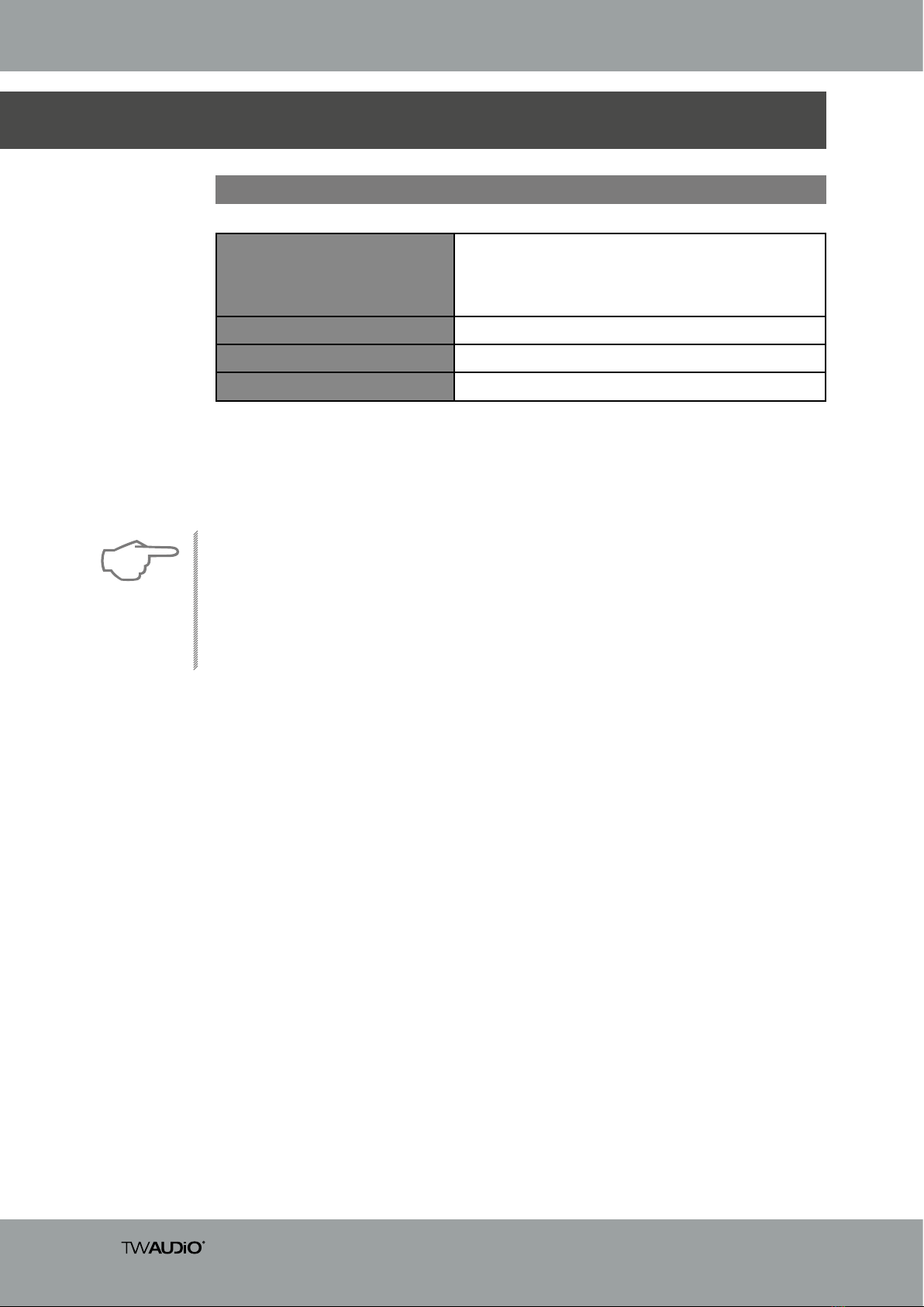
3. Technical specifications .................................................................................................. 8
3.1 Data sheet............................................................................................................... 8
4. Commissioning............................................................................................................... 9
4.1 Setup ...................................................................................................................... 9
4.2 Necessary tools for setting up the flown system ...................................................... 9
4.3 Using the VERA LA900i load adapter in flown systems........................................... 10
4.4 Secondary safety component in the flown system ................................................. 13
4.5 Wind load in the flown system ............................................................................... 14
4.6 Angle settings in a flown system ............................................................................ 15
4.7 Installation position of the lock washer................................................................... 17
4.8 Preparing the first VERA20i loudspeaker for a flown system................................... 18
4.9 Setting up the first VERA20i loudspeaker in a flown system ................................... 20
4.10 Preparing the following VERA20i loudspeakers for a flown system....................... 23
4.11 Setting up the following VERA20i loudspeakers in a flown system ....................... 24
4.12 Preparing the last VERA20i loudspeaker for a flown system................................. 27
4.13 Setting up the last VERA20i loudspeaker in a flown system ................................. 28
4.14 Preparing a subwoofer for a flown system ........................................................... 30
4.15 Setting up the subwoofer in a flown system......................................................... 31
4.16 Preparing the last subwoofer for a flown system.................................................. 34
4.17 Setting up the last subwoofer in a flown system .................................................. 35
4.18 Setting up the VERA20i and subwoofer in a flown system ................................... 37
4.19 Cardioid application of the VERAS17i loudspeaker in a flown system .................. 39
4.20 Rigging tracks ..................................................................................................... 43
5. Transport and Storage.................................................................................................. 44
6. CE Declaration of Conformity........................................................................................ 45
7. Disposal ....................................................................................................................... 45

VERA RF600i Assembly Instructions
5
1. Safety | Intended use
To avoid risks please observe the following safety instructions when using accessories.
The VERA RF600i rigging frame was developed for professional use in sound systems. The
rigging frame may only be used by trained and qualified personnel.
Note the operating modes described in this operating manual. Other uses are not permis-
sible.
Damage caused by improper use is not covered by TW AUDiO.
Before each installation, check the integrity of the VERARF600i rigging frame and ensure that
all components are in perfect condition.
The scope of delivery includes a specified load adapter with shackle. Only use this load
adapter.
The VERA RF600i rigging frame may only be used with the VERA20i and/or subwoofers.
These assembly instructions describe how to use the VERARF600i rigging frame. Any other
use shall be deemed improper and may result in damage or even injury.
Modifications or alterations to individual parts of the VERA RF600i rigging frame and the
VERA LA900i load adapter are not permitted! Danger to life!
The VERA RF600i is an accessory designed both for indoor and outdoor use.
The VERA RF600i rigging frame may only be used by trained and qualified personnel.
Personnel must check the VERA RF600i for its full suitability before each use.
When visible damage to any part of the VERA RF600i rigging frame is detected, it must be
decommissioned immediately.
Before mounting the VERARF600i rigging frame, all attachment points – such as ceilings and
crossbeams – must be checked for full load capacity and stability.
The VERA RF600i accessory is specified for a load of not more than 24 VERA20i loudspe-
akers or twelve VERA S17 loudspeakers or ten VERAS32i loudspeakers. This load capacity
must never be exceeded!
WARNING
WARNING
WARNING
WARNING
WARNING
CAUTION

VERA RF600i Assembly Instructions
6
When moving (assembling, dismantling, maintaining) the VERARF600i rigging frame with
VERA20i and/or Subwoofers, ensure sufficient space to prevent collisions with other objects.
When working with heavy loads exceeding 20 kg (44 lbs.), use suitable aids (dollies, hoisting
slings, etc.). Multiple persons may be required depending on the situation.
When installing the VERA RF600i rigging frame, be careful not to pinch or twist the power
cables or other cables attached to the VERA20i and/or subwoofers! The respective national
electrotechnical regulations apply.
All screw connections should be checked when the VERARF600i rigging frame is installed. If
there are loose screws, tighten them. If this is no longer possible, the screws must be repla-
ced.
Whenever you make changes to the flown system, always use new cylinder screws (Item2)
and lock washers (Item3) as delivered with the product. These items are available from
TW AUDiO.
WARNING
WARNING
WARNING
CAUTION
NOTE
Please keep all mounting elements away from children! The small parts can easily be swallo-
wed and lead to suffocation!
WARNING

VERA RF600i Assembly Instructions
7
1. VERA RF600i rigging frame – powder-coated surface ............................................ 1 pc
2. Cylinder screws M8 x 16-12.9 ...............................................................................7 pcs
3. Locking washer VS-8-1.4301...............................................................................7 pcs
4. Front rigging end plate – powder-coated surface..................................................4 pcs
5. Middle rigging end plate – powder-coated surface ...............................................2 pcs
6. Load adapter with VERA LA900i shackle ............................................................... 1 pc
7. M8 x 25-12.9 fitting screw.....................................................................................2 pcs
8. Washer D8.4 ........................................................................................................2 pcs
9. Hexagon nut with clamping part M8-8..................................................................2 pcs
2. Overview
2.1 Scope of delivery
Figure 2.1 – Overview
1
6
45
23
789

VERA RF600i Assembly Instructions
8
3. Technical specifications
3.1 Data sheet
Maximum load capacity
600 kg, with safety factor 10 against breakage.
This corresponds to e.g. 24x VERA20i or
12x VERA S17i or
10x VERA S32i units.
Dimensions (h x w x d) 80 x 600 x 600 mm (3.1 x 23.6 x 23.6 in)
Weight 16,7kg (36 lbs)
Surface Powder-coated
Please note that the loudspeakers
• VERA S17i
• VERA S32i
are named as subwoofers in the manual.
Please also note that the VERA S17i loudspeaker is used as an example for all graphics with
subwoofer systems.
NOTE

VERA RF600i Assembly Instructions
9
4. Commissioning
4.1 Setup
The VERA RF600i rigging frame is designed both for hanging operation. TW AUDiO provides
a wide range of accessories to securely attach the rigging frame.
TW AUDiO recommends using only the accessories specified by TW AUDiO for securing and
mounting the rigging frame.
4.2 Necessary tools for setting up the flown system
• Torque wrench
• Bit insert for torque wrench: TX45
• SW13 fork wrench
Whenever you make changes to the flown system, always use new cylinder screws (item 2
on scope of delivery) and lock washers (item 3 on scope of delivery) as delivered with the
product.
These items are available from TW AUDiO.
Keep the following tools ready for assembling the flown systems:
WARNING
NOTE

VERA RF600i Assembly Instructions
10
4.3 Using the VERA LA900i load adapter in flown systems
Figure 4.3.1 – VERALA900i load adapter
Attach the VERA LA900i load adapter to the VERA RF600i rigging frame as shown in figure
4.3.2!
Use items 7, 8 and 9 from the scope of delivery (see figure 2.1).
Figure 4.3.2 – Mounting the VERALA900i load adapter
WARNING

VERA RF600i Assembly Instructions
11
Figure 4.3.3 - VERALA900i load adapter at pin point 15 – forward orientation
The VERA LA900i load adapter’s design allows for four different usage scenarios.
The two integrated slots allow both integer and half-integer settings.
The marker on the shackle on the VERA LA900i load adapter indicates the currently selected
value. This can be seen in Figures 4.3.3 to 4.3.6.
The following illustrations show the different applications in an example:
Use the EASE Focus simulation software to design system setups with the VERARF600i rig-
ging frame as well as the associated VERA20i and / or subwoofers. The simulation can be
used to determine the correct pin points for your application.
Inserting the two screws into 15 and 16 will result in 15 as pin point for the forward-facing
VERA LA900i load adapter.
Figure 4.3.4 - VERALA900i load adapter at pin point 15.5 – forward orientation
Moving the VERA LA900i load adapter from 16 to 17 will result in 15.5 as the new pin point.
18 17 16 15 14 13 12
18 17 16 15 14 13 12
NOTE

VERA RF600i Assembly Instructions
12
Figure 4.3.6 - VERALA900i load adapter at pin point 15.5 – reverse orientation
Moving the VERA LA900i load adapter from 15 to 14 will result in 15.5 as the new pin point.
Figure 4.3.5 - VERALA900i load adapter at pin point 16 – reverse orientation
Inserting the two screws into 15 and 16 will result in 16 as pin point for the backward-facing
VERA LA900i load adapter.
18 17 16 15 14 13 12
18 17 16 15 14 13 12

VERA RF600i Assembly Instructions
13
4.4 Secondary safety component in the flown system
Figure 4.4.1 – Secondary safety component example
Attach a second, separate safety component to the “for safety wire” points D and E. This can
be safety chains for example.
Figure 4.4.2 – Secondary safety component example
Please obtain about regulations of secondary safety components in the place where you wish
to operate the system.
main load
safety
E
D
WARNING
NOTE

VERA RF600i Assembly Instructions
14
4.5 Wind load in the flown system
Before setting up the system outdoors, consider unforeseeable wind conditions at the ope-
ration site!
Disassemble your system immediately when wind forces exceed 8bft (34 to 40kn –
38.5 to 46 mph)!
Make sure that there are no persons in the close proximity of the flown system!
Make sure that your system will not be operated at wind forces over 6 bft (22 to 27 kn –
24.2 to 30.45 mph).
Make sure that there are no persons in the immediate vicinity of the system structure!
WARNING
WARNING

VERA RF600i Assembly Instructions
15
4.6 Angle settings in a flown system
Figure 4.6.1 – bracket
1. Attach the bracket (see figure 4.6.1) as described in the angle settings table (see figure
4.6.2). The bracket comes with the VERA20i loudspeaker (position 5 of the scope of deli-
very) and the subwoofers (position 4 of the scope of delivery).
2. When setting up the flown system with VERA20i loudspeakers, please refer to the detailed
views for each individual angle setting as seen on the next page.
0°
0,3°
0,8°
1,5°
2,4°
3,5°
4,9°
6,8°
9,1°
12
12°
9,1°
6,8°
4,9°
3,5°
2,4°
1,5°
0,8°
0,3°
0°
Figure 4.6.3 - Angle settings in the flown system with VERA20i loudspeakers
NOTE
Figure 4.6.2 – Angle settings table
angle settings
Angle Combinations
0° F - N
0,3° B - I
0,8° C - K
1,5° A - H
2,4° F - M
3,5° D - K
4,9° G - M
6,8° E - K
9,1° G - L
12° G - K

VERA RF600i Assembly Instructions
16
Figure 4.6.4 – Detail views of the angle settings from figure 4.6.3
0°
0,3°
0,8°
1,5°
2,4°
3,5°
4,9°
6,8°
9,1°
12°

VERA RF600i Assembly Instructions
17
4.7 Installation position of the lock washer
Make sure that the lock washers (item 3 on the scope of delivery) are installed as shown in
figure 4.7.1!
Reverse installation of the lock washer would cause the lock washer to have no biasing force
and accordingly lose its effect!
Figure 4.7.1 – Installation position of lock washer (position 3)
2 3
WARNING

VERA RF600i Assembly Instructions
18
4.8 Preparing the first VERA20i loudspeaker for a flown system
Figure 4.8.1 – Attaching the splay links to the first VERA20i loudspeaker
1. Start by attaching splay links on the front top left and right of the VERA20i loudspeaker
(item 4 on the scope of delivery).
2. Attach each splay link using one cylinder screw, item 2 and one lock washer, item 3 from
the VERA20i loudspeaker scope of delivery.
3. Make sure to properly insert the lock washer as described in section 4.7!
4. Make sure that the screws with the lock washers are only attached and not tightened.
Figure 4.8.2 – Attaching the brackets to the first VERA20i loudspeaker
5. Turn the bracket and attach it to the VERA20i loudspeaker (hole F).
6. Attach the brackets on the rear top left and right of the VERA20i loudspeaker (item 5 on
the scope of delivery).
7. Attach each splay link using one cylinder screw, item 2 and one lock washer, item 3 from
the VERA20i loudspeaker scope of delivery.
8. Make sure to properly insert the lock washer as described in section 4.7!
9. Make sure that the screws with the lock washers are only attached and not tightened.
1.
2.
7.
5.
WARNING
WARNING

VERA RF600i Assembly Instructions
19
Figure 4.8.3 – Attaching the splay links to the first VERA20i loudspeaker
10.Attach splay links on the front bottom left and right of the VERA20i loudspeaker (item 4
on the scope of delivery).
11.Attach each splay link using one cylinder screw, item 2 and one lock washer item 3 from
the VERA20i loudspeaker scope of delivery.
12.Make sure to properly insert the lock washer as described in section 4.7!
13.Make sure that the screws with the lock washers are only attached and not tightened.
Figure 4.8.4 – Attaching the brackets to the first VERA20i loudspeaker
14.Attach the bracket to the VERA20i loudspeaker at the angle that you previously calculated
using the EASE Focus simulation software.
15.Attach the brackets on the rear bottom left and right of the VERA20i loudspeaker (item 5
on the scope of delivery).
16.Attach each splay link using one cylinder screw, item 2 and one lock washer, item 3 from
the VERA20i loudspeaker scope of delivery.
17.Make sure to properly insert the lock washer as described in section 4.7!
18.Make sure that the screws with the lock washers are only attached and not tightened.
10.
11.
14.
16.
WARNING
WARNING

VERA RF600i Assembly Instructions
20
4.9 Setting up the first VERA20i loudspeaker in a flown system
3. Place the first VERA20i loudspeaker with its back on the floor. Place a pad under the
loudspeaker to avoid damage.
4. Insert the splay links of the VERA20i loudspeaker into the openings at the
VERA RF600i rigging frame.
Figure 4.9.1 – Front Mounting of the first VERA20i loudspeaker at the VERA RF600i rigging frame
2. Use the EASE Focus simulation software to determine the amount of loudspeakers and
splay angles required for your application.
To set up a flown system with the VERA20i loudspeakers, proceed as follows:
1. Please note that setting up the VERA RF600i rigging frame always requires two persons!
5. Attach the splay links to the left and right side of the VERA RF600i rigging frame using one
cylinder screw, item 2 and one lock washer, item 3 from the VERA20i loudspeaker scope
of delivery.
6. Make sure to properly insert the lock washer as described in section 4.7!
7. Make sure that the screws with the lock washers are only attached to the
VERA RF600i rigging frame, but not tightened.
4.
5.
WARNING
WARNING
WARNING
NOTE
Table of contents