Two-Rock Sensor 22 User manual

Two-Rock
Sensor
22/35/50
OWNERS MANUAL

Dear Customer,
Thank you for your purchase of a Two-Rock!
As a discerning guitarist, you know the road to great tone begins with
great components.
Our Classic Design, carefully selected parts and hand-built approach
combine to make an extremely versatile instrument.
Please take the time to read this manual. We hope it will answer any
questions that you may have.
We extend a warm welcome to you as a member of a select group of
musicians who have chosen a Two-Rock amplifier.
Important Safety Instructions
1. Read these instructions
2. Keep these instructions
3. Heed all warnings
4. Follow all instructions
5. Do not use this apparatus near water
6. Clean only with dry cloth
7. Do not block any ventilation openings. Install in accordance with the manufacturer’s instructions
8. Do not install near any heat sources such as radiators, heat registers, plugs, and the point
where they exit from the apparatus
9. Protect the power cord from being walked on or pinched particularly at plugs and the point
where they exit from the apparatus
10. Only use attachments/accessories specified by the manufacturer
11. Unplug this apparatus during lightning storms or when unused for long periods of time
12. Refer all servicing to qualified service personnel. Servicing is required when the apparatus has
been damaged in any way, such as power-supply cord or plug is damaged, liquid has been spilled
or objects have fallen into the apparatus, the apparatus has been exposed to rain or moisture,
does not operate normally, or has been dropped
13. CAUTION: To disconnect the unit completely from the MAINS, unplug the unit. Turning the power
switch off does not disconnect the unit completely from the MAINS.

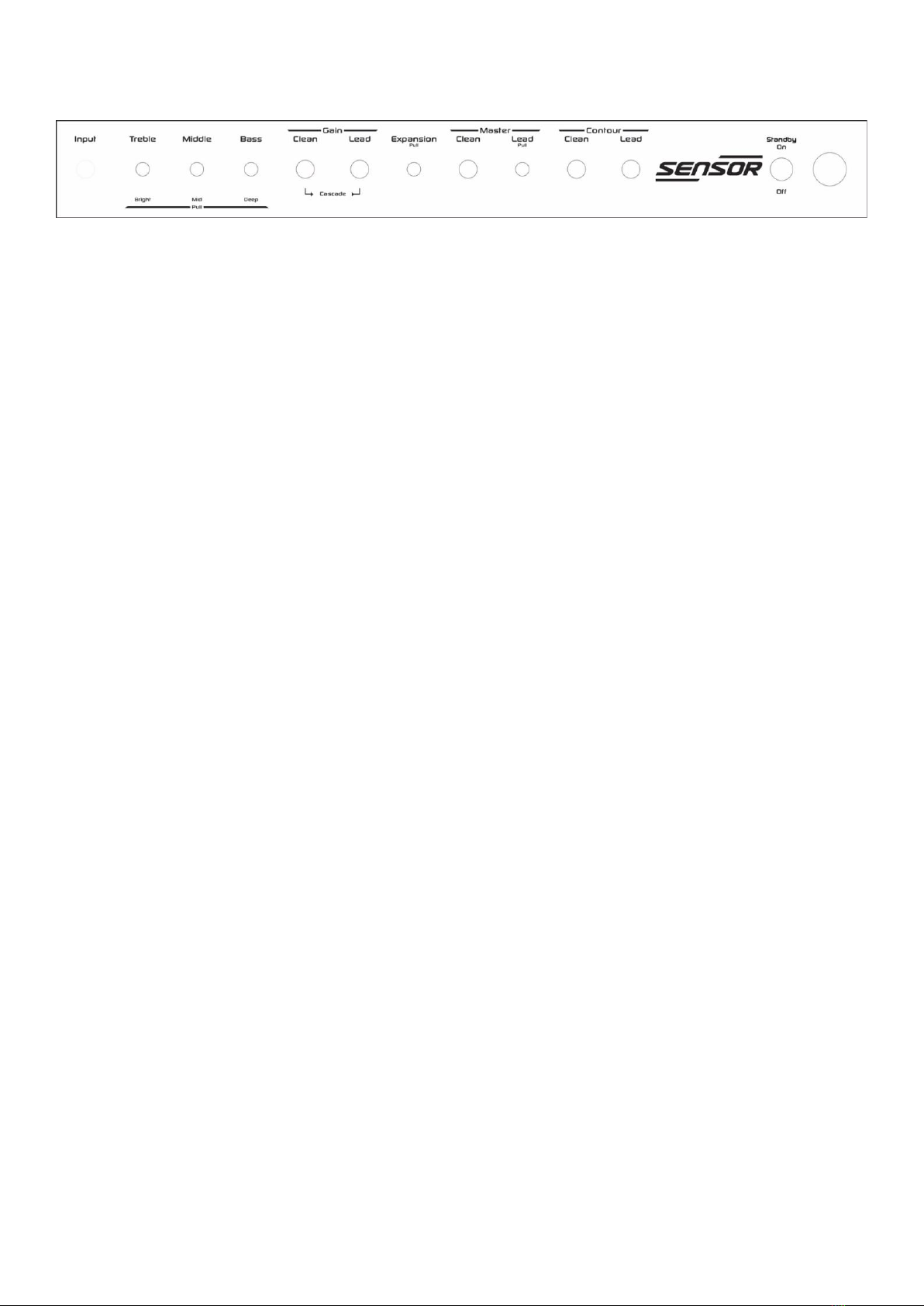
Front Panel Functions
Input - High impedance input to the amplifier. Plug in your instrument here.
Treble + Pull Bright - Adjusts the high frequency response. At lower settings of this control the
tone will be warmer and smoother. As you turn this control up the highs become more prominent
and aggressive adding gain to the signal as well. This control is very interactive with the BRIGHT
switch, MID control, and DEEP switch. In the full counter-clockwise position, high frequencies are
bypassed to ground. In the full clockwise position, high frequencies are allowed to pass to the next
gain stage. Pulling the knob to the “out” position: boosts the high frequency response. This is
most effective when the Gain control is set at 12 o’clock or lower. This is great for adding sparkle
to clean tones. The effect is less dramatic as the Gain control is adjusted past the 12 o’clock
position.
Middle + Pull Mid - Adjusts the midrange response. At low settings of this control the tone will be
“scooped” of midrange response, emphasizing the highs and lows. As this control is turned up, the
midrange frequencies are increased. This creates the “body” of your guitar’s tone and is very
critical to both the tonality, feel and overall response of the amplifier. Higher settings of this control
also help your tone to cut through the mix in both a live band situation and when playing the amp
outdoors. In the full clockwise position, mid-range frequencies are allowed to pass to the next gain
stage. Pulling the knob to the “out” position: Midrange is further boosted.
Bass + Pull Deep - Adjusts the bass response. In the full counter-clockwise position, low
frequencies are cut. In addition, the response of the treble and mid-range controls is greatly
reduced. It’s easiest to start with this control at noon, then adjust to taste. In the full clockwise
position, low frequencies are allowed to pass to the next gain stage.
Pulling the knob to the “out” position: Boosts the lower bass frequencies. This low frequency
contour switch also shifts the emphasis from the upper bass and low mid frequencies to the lower
bass frequencies which helps smooth out and clarify the midrange response.
Gain –Clean - Adjusts the overall gain of the amplifier. Start with this control in the 12 o’clock
position then adjust to taste. This control determines the initial character of your tone, from
cleaner/brighter tones at low settings to fatter/warmer tones at higher settings. As you turn this
control up it also introduces more gain and bass into the signal path, and reduces the amount of
available clean headroom especially when the master volume is set higher.
Gain –Lead - Adjusts the input level (gain) of the lead channel
NOTE: An internal EQ (Preset at Factory) is located post lead gain in the circuit. This EQ is active
with and without the expansion engaged.

Expansion/Pull On - Pulling the knob engages the Expansion circuit. This feature cuts the EQ
section out of the signal path allowing more input signal to hit the gain stage. With it engaged it will
allow the natural frequencies of the input tube and guitar to come through. This adjustable control
allows how much gain passes through and as it is turned up (clockwise) it will increase the amount
of high and mid frequencies. When engaged with the lead channel on, this allows the internal post-
gain EQ to be isolated. Expansion function is foot-switchable and the push/pull control
needs to be in the “In” position for the footswitch to work.
Master –Clean - Adjusts the overall output level of the amplifier. At lower settings on this control
the amp will be much cleaner sounding as well as lower in volume. As this control is turned up the
power section of the amp begins to work harder which increases sustain, fullness, and touch
dynamics as well as increasing the volume of the amplifier. At higher settings on this control the
power section will be pushed into natural overdrive especially if the Gain control is set higher.
Master –Lead - Adjusts the output level of the lead channel. Pulling the knob engages the lead
channel. Lead function is foot-switchable and the push/pull control needs to be in the “In”
position for the footswitch to work.
Contour Clean - The contour control is an active wide band sweep. In the 12 o’clock position, the
amp’s frequency response is flat. Counterclockwise rotation reduces high end response and
increases low frequencies. Clockwise rotation decreases low end and increases the high
frequency response. This control is very useful for maintaining preamp tone control settings, while
allowing a global adjustment to compensate for differences in room acoustics, speaker cabinets,
or bright to dark guitars (single coils to humbuckers, for example). This control also actively
reduces the articulation available, allowing a softer setting, or extremely open and revealing,
depending on your individual style and requirements.
Contour Lead –Same as above but independently affects the lead channel.
STANDBY - This switch should be in the down/STANDBY position before you place the Power
switch to the up/ON position. After 20 seconds or more, place the Standby switch in the “up”
position to play the amplifier. When you are taking a break from playing the amp you can leave the
amp “powered up” and simply switch to the “stand-by” position to mute the output of the amplifier
and prolong power tube life.
Indicator Lamp - This lamp will illuminate when the rear panel power switch is in the “up” position,
indicating the unit is receiving A/C power.

Rear Panel Functions
A/C Input - Connects the amplifier to A/C power via the power cord supplied. Unless otherwise
specified, your amplifier is designed to operate on 120 volts A/C, 60 cycles.
Fuse - See Fuse Chart
Power Switch - Turns power on.
Speaker Output Jacks - There are 4 speaker output jacks; Dual 4, 8, and 16 ohms.
NEVER OPERATE YOUR AMPLIFIER WITHOUT A PROPER SPEAKER LOAD CONNECTED.
Be sure to match the impedance of your cabinet with the impedance (output) of the amplifier.
- Effects Loop –This is a fully buffered tube circuit which incorporates Send and Return
level controls. Both controls are active even if no effects are introduced into the
system. The loop also has the ability to be run in series or parallel. The circuit incorporates
two 12AX7VKA tubes. These tubes are run as a cathode follower pair that creates a unity
gain high/low impedance system. Perfect analog circuit for running signal in and out of
analog or digital gear with minimal insertion loss.
Send - Sends signal to effect’s input. (1/4” Mono Jack)
Send Level + Pull Bright - Adjust the amount of signal that passes from the preamp stage to the
Effects loop Send jack. Adjust this control to keep clipping down within effect signal chain.
A unity setting with nothing inserted into loop is 3 o’clock.
Pulling the knob to the “out” position: Brightens the signal of the effects send, if needed, when
the high frequencies are compromised within some digital effects or long cable runs.
Return –Returns signal from effect’s output. (1/4” Mono Jack)
Return Level + Pull Bright - Adjust the amount of signal that is returned from the effect’s output.
Adjust this control to minimize unwanted signal clipping in the power stage of the amplifier.
A unity setting with nothing inserted into loop is 12 o’clock.
Pulling the knob to the “out” position: Brightens the signal of the effects send, if needed, when
the high frequencies are compromised within some digital effects or long cable runs.

Parallel/Series Switch - The switch allows the user to choose how the wet and dry
signals interact with each other. With the switch set to Parallel the signal will be split
with one side “wet” running from the preamp to effects to power stage, while the “dry”
signal runs from the preamp to the power stage. This setting is more versatile with
vintage effects that don’t have any wet/dry mixing controls. With the switch set to Series
the signal will not be split and will run straight from the preamp through the effects and then
intothe power stage of the amplifier. This setting will be better suited to rack or digital gear
that has onboard mixing controls. With nothing plugged into the loop, the Parallel
setting will yield a fatter and fuller signal.
Footswitch Jack - The footswitch connects here using a ¼” stereo cable. The Expansion and
Lead functions can be activated via the footswitch. The respective front panel Push/ Pull pots must
be in the “off,” or “in” position, to enable the footswitch functions.
S/N - Your serial number is located here. We strongly suggest that you record this number and
have it handy in case you need service, or in the event that your amp is lost, stolen, or damaged.
Fuse Chart
All Fuses are 3AG Type 250 Volt, SLO-BLO
Export 100V: Domestic 120V: Export 220V, 230V, 240V:
2A –22/35 Watt 2A –22/35 Watt 1A-22/35 Watt
2.5 - 50 Watt 2.5 - 50 Watt 1.6 - 50 Watt
FOOTSWITCH
WARNING! No user serviceable parts inside! Refer to qualified service person only.
LINE CORD- For your safety, connect to grounded A/C receptacle only.

Tube Complement
V1- 12AX7, Input and Gain
V2- 12AX7, Lead Input and Gain
V3- 12AX7WA, Effect’s loop buffer
V4- 12AX7WA, Effect’s loop buffer
V5- 12AX7, Phase Inverter
V6-V7 - 6L6 (35/50 watt) or 6V6 (22 watt) Power Tubes
Each fine production tube is tested and matched to our exacting specifications. External bias
adjustment and test points are located on the chassis near the output tube sockets. A digital
voltmeter and small screwdriver are required for bias adjustment.
BIAS ADJUSTMENT PROCEDURE:
-Power up unit and connect proper speaker load
-DO NOT have an instrument connected to the input during the biasing procedure!
-Take unit off standby and allow a few seconds for the circuit to stabilize.
-Set multi-meter to read DC Volts
-With meter grounded to chassis and + probe inserted into test point, measure voltage.
-Using a small flat head screwdriver, insert into Bias pot and turn slowly adjusting Bias
level
Below is a limited list of comparable tube types:
6L6: 6L6GC, 7581, 5881
6V6: 6V6S, 6V6GT
Bias Ranges: Are measured and set in Volts. But can be measured and set in milliamps.
6L6 type tubes: .060V to .070V for 35watt version Factory Setting: .064V
6V6: tube types: .044V to .058V for 22watt version Factory Setting: .050V
Do not set bias higher than recommended as it can lead to tube failure or failure within the
amplifier!

We know your new Two-Rock amplifier will provide many hours of
enjoyment and inspiration in the years to come.
This manual is a resource for some of your questions.
Please contact us with any other questions or comments that you may
have. We look forward to hearing from you!
PHONE: 1(707)584-TONE (8663) (M-F 9am-5pm PST)
ADDRESS: Two-Rock Amplifiers, LLC
619 Martin Avenue, Suite 5
Rohnert Park, CA 94928
CONTACT: info@two-rock.com
WEB: www.two-rock.com

Two-Rock Amplifiers, LLC
619 MARTIN AVENUE, SUITE 5
ROHNERT PARK, CA 94928
707-584-8663
www.two-rock.com
SERIAL NUMBER: _____________________________

Other manuals for Sensor 22
1
This manual suits for next models
2
Table of contents