TXAM Pumps SPC1000 User manual

Title: SPC1000 Basic Pump Controller User Manual
Page: 1of 7
Doc # 10-000-106
Revision: 2
Date: 04/09/2020
Reproduce of this Manual in whole or part, by any means, for any purpose is prohibited. Additional copies may be obtained by contacting
TXAM Pumps QA Department.
Specifications
•Nominal Battery Voltage: 12V
•Plastic enclosure with mounting tabs
•Fuse Type: 15 Amp mini automotive blade fuse
•Dimensions: 3.25" wide by 4.4" long by 1.7" deep
•Cycles set range: 1 to 10 Cycles per Minute
•On Time set range: 0.5 seconds to 5.5 seconds, in half second increments
•Temperature Control set range: 30°F to 90°F
•RS485 connection for Modbus remote control
Features
•Rotary knob control for quick change of parameter settings
•On Off Power Switch, with quick start up
•Three Digit Seven Segment display, readable in sunlight
•Reliable solid state protected circuitry.
•Replaceable Fuse for circuit/motor protection
•Temperature probe connection
•Display selection indicated by color LED indicators
•Pluggable terminal block for Modbus Connection and pump inhibit input
•Pump prime feature
•Four 0.250 spade Lug connectors for attaching battery and motor
•Battery voltage can be displayed
•Low Battery Voltage Shutdown
•Temperature ON and OFF set points can be displayed
•Probe temperature can be displayed
•Color Coded motor and battery connections
•Cycles per Minute Timer with Temperature and Remote Input inhibit
Controls and Indicators
•Five LEDs for Display indication
•Rotary knob for parameter setting
•Push rotary knob to save parameter
•Three digit seven segment display
•LEDs indicates the current display selection
•ON/OFF Power Switch
Title: SPC1000 Basic Pump Controller User Manual
Page: 2of 7
Doc # 10-000-106
Revision: 2
Date: 04/09/2020
Reproduce of this Manual in whole or part, by any means, for any purpose is prohibited. Additional copies may be obtained by contacting
TXAM Pumps QA Department.
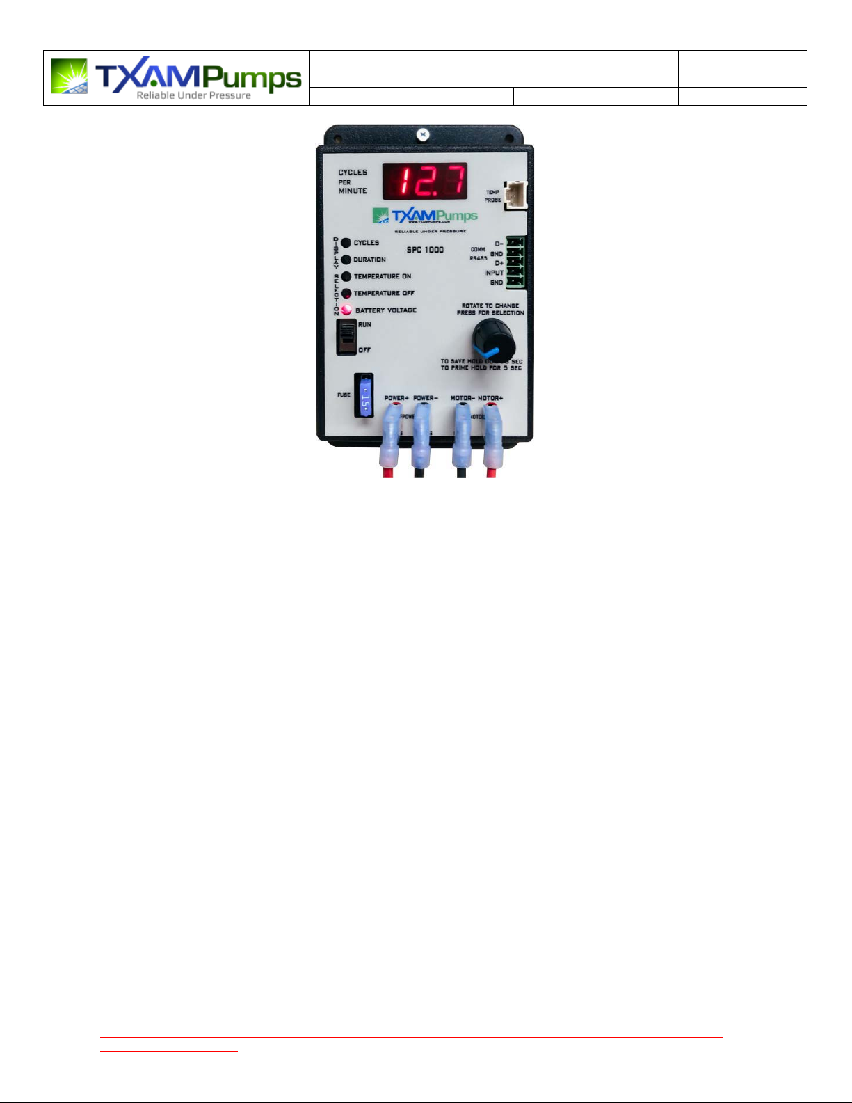
Figure 1 - SPC1000 Basic Pump Control Timer
Operation
When the Power Switch turns on a quick self test is performed and then the battery voltage display will
be selected and displayed on the seven segment display.
Pressing down on the Rotary knob will select/cycle through different displays as indicated by the LEDs.
The display parameters are Cycles per Minute, Duration (on time), Temperature ON setpoint,
Temperature OFF setpoint and Battery Voltage / Temperature probe reading.
To set an operating parameter (such as duration), press the rotary knob down quickly (it will click) to
cycle to the parameter you want to display or change. Each press goes to a different parameter that is
displayed. When you have selected the parameter you want to change as indicated by the LEDs, you
rotate the knob clockwise or counter clockwise to change this parameter setting up or down. When you
have selected the new value you want Press and Hold the knob down for approximately three seconds,
you will see SAV displayed indicating the new parameter set point has been saved. If you do not press
and hold until SAV is indicated the setting is not saved. Quit pressing down when SAV is displayed to
save your setting.
If you continue to hold down the knob for a couple of more seconds after SAV is display a pump prime
cycle will occur (and the parameter will NOT be saved). The display will indicate a prime cycle by
displaying PRI and then start a 30 second count down. During Prime the Pump will remain on until
timed out, after time out normal pump operation will begin. Pressing the knob again during a prime
cycle will extend the ON time another 30 seconds. If you want to abort the prime cycle, you must turn
off the power switch.

Title: SPC1000 Basic Pump Controller User Manual
Page: 3of 7
Doc # 10-000-106
Revision: 2
Date: 04/09/2020
Reproduce of this Manual in whole or part, by any means, for any purpose is prohibited. Additional copies may be obtained by contacting
TXAM Pumps QA Department.
Timer Setup
Connect the Battery to the POWER terminals, and connect the Pump to the MOTOR terminals.
If using a temperature probe, it may be connected at any time. If a probe is connected temperature
control will be active. If no probe is connected, temperature control is not used.
Battery voltage must be above 10 volts for operation. The display will switch to the battery display when
the battery gets too low for pump operation. Lob will flash on the display along with the voltage and
temperature, to indicate the voltage is too low for operation.
A Plug-In Terminal Block is used for connection to Modbus and/or the Remote Inhibit input.
A dry contact connected to the Input will inhibit pump operation when closed and this will be indicated
by INH being displayed when pump operation is inhibited.
Other Operation Features and Information
Plugging in the external temperature probe will activate temperature control in the CpM and On-Off
modes. When in Modbus mode of operation you must have probe connected for Modbus to have the
ability to enable/disable temperature operation. If Modbus enables temperature control, it will not be
active or show the status of being active until a probe is connected. If no external probe is connected
(shutoff with temperature is disabled) the Temperature ON and Temperature OFF display selections will
display a period (.) in the ones digit, no period is shown if the probe is connected.
Voltage cut back is always enabled in the CpM mode of operation but is not enabled for Modbus or
ON/Off control. If the timer is in actual voltage cut back there will be a period under the c (cycles
selection on the display) to indicate cutback due to low voltage. If the unit is operating normally the
period will not be seen.
Battery voltage is accurate to a couple of tenths. So use a voltage meter to verify when you need
accuracy.
Some fuses maybe hard to remove or install, grabbing the fuse with pliers and slowly rocking the fuse
back and forth will make it easier to remove and install.
While in Shutdown (Sdn on display) you may have to hold the switch down about 1 sec to get display
back on for it to change to the next display selection.
The Duration (On) cycle is run first after Power On Reset.
The display will blank after a time out period, but one of the LEDs will be On. If the display is blank, press
the rotary knob quickly and the display will come back on.
Always power off timer prior to any work on pump.

Title: SPC1000 Basic Pump Controller User Manual
Page: 4of 7
Doc # 10-000-106
Revision: 2
Date: 04/09/2020
Reproduce of this Manual in whole or part, by any means, for any purpose is prohibited. Additional copies may be obtained by contacting
TXAM Pumps QA Department.
To change type of operation hold down the rotary encoder knob while powering up the timer. You will
see the display change from CYC for cycles per minute operation, then ON OFF for On time Off time
operation and bUS for Modbus control. When it displays the type of operation you desire release the
encoder knob. Then you will momentary see SEL displayed followed by the mode you selected. By
default it will go to Battery voltage display selection and begin to display the battery voltage for about
three seconds and then follows by displaying temperature.
If you select Modbus operation (bUS) as soon as it says SEL, press the Knob down and hold it until it
displays Adr and then Set, at this point release the knob and a number will be displayed. This is the
Modbus address, rotate the knob until you have the Modbus address you want. Then press and release
the knob, it will say rdY for ready. The timer is now ready to operate with the Modbus slave address you
selected. Modbus operation is RTU mode, 8 data bits, no parity, 9600 bps. Address range is settable
from 1 to 60, with a default of 20.
The first time the timer is powered up in the Modbus mode the timer will be in a halt mode. Once
Modbus has requested the unit to turn on, future power ups will operate as per the last Modbus
request.
Modbus (Remotely Control Mode, bUS Mode)
The Modbus mode requires that you connect the RS485 signal to the pluggable terminal block. A
Modbus Master will control all pump operations via communication over the RS485 connection. This
connection requires three wires, Data+, Data-, and Ground. The baud rate is 9600, Modbus Protocol
Mode - RTU Slave, 1 stop bit, No parity. Modbus Address is selectable from 1 to 60. Modbus will control
operation based on information written to the register map (See Appendix A). No termination is on the
RS485 connection-user provides the required external 120 ohm resistor if needed.
During Modbus operation the rotary knob does not have any function (other than displaying of
information) as all operation is controlled by the Modbus master. The push button switch will operate as
follows. If you press the Push button on the bottom center the display selection LEDs will change what is
being displayed.
During Modbus operation the Display will normally display bUS when running under Modbus control
and will display hLt when Modbus commands the timer to stop.
When in Modbus mode after power up in the run mode they will be 4 short pump cycles, to indicate the
timer is under Modbus control.
NOTE: In the event of a power fail (or when powering Off to On) the timer operation will be as last as
commanded by Modbus. In other words, if the timer was in the halt mode, when power comes on it will
be in the halt mode. If the timer was running when there was a power off, it would resume operation
when power returns. Also, in Modbus mode you may use the input from an external contact to halt
operation and it can be read it via a Modbus register.
If Modbus is inhibiting operation, the display will flicker when it should be blank. If the display is active
you will see hLt flash and toggle with the actual display selection reading.
Title: SPC1000 Basic Pump Controller User Manual
Page: 5of 7
Doc # 10-000-106
Revision: 2
Date: 04/09/2020
Reproduce of this Manual in whole or part, by any means, for any purpose is prohibited. Additional copies may be obtained by contacting
TXAM Pumps QA Department.
When you read the holding register setpoint temperature via Modbus, if it has not been changed from
its initial condition data will be in the low byte, once changed the value is in the high byte during read
back.
Timer Mode Setup – Cycles per Minute
With Timer in Modbus Mode, set the following registers as follow:
•Holding register 40000 as 0x00
Set timer mode to cycles per minute
•
Holding register 40001 as 0x0205
1st byte = 05
05 x .5 sec = 2.5 sec pump on time
2
nd
byte = 02 2 cycles per minute
•Coil register 00000 as 0x1
Start operation
Timer Mode Setup – ON/OFF Timer
With Timer in Modbus Mode, set the following registers as follow:
•Holding register 40000 as 0x01
Set timer mode to On/Off timer
•Holding register 40001 as 0x1050
1st byte = 0x50
80 x .5 sec = 40 sec pump off time
2
nd
byte = 0x10
16 x .5 sec = 8 sec pump on time
•Coil register 00000 as 0x01
Start operation

Title: SPC1000 Basic Pump Controller User Manual
Page: 6of 7
Doc # 10-000-106
Revision: 2
Date: 04/09/2020
Reproduce of this Manual in whole or part, by any means, for any purpose is prohibited. Additional copies may be obtained by contacting TXAM Pumps QA Department.
APPENDIX A:

Title: SPC1000 Basic Pump Controller User Manual
Page: 7of 7
Doc # 10-000-106
Revision: 2
Date: 04/09/2020
Reproduce of this Manual in whole or part, by any means, for any purpose is prohibited. Additional copies may be obtained by contacting
TXAM Pumps QA Department.
Revision History
Revision
Descriptions
Drawn
Checked
Approved
Date
0
Initial release – merged 2 existing documents into 1
AC
LG
SB
10/03/2019
1
Added Timer Mode example. Corrected register
40001 example on Modbus Map Table.
AC
LG
SB
11/06/2019
2
Removed 4-20 feature from specifications. Added
pump inhibit input to features. Changed product
picture.
JS
AC
AC
04/09/2020
Table of contents


