TxPORT 1558A User manual

TRANSPORT
®
Introduction
Reference Manual
34-00228
2nd Edition
1558A
APS

General
Introduction ................................................................ 1-1
Design Highlights ....................................................... 1-1
Specifications ............................................................. 1-1
FCC Requirements....................................................... 1-2
Canadian Emissions Requirements ............................. 1-3
Warranty ..................................................................... 1-3
Ordering Numbers ...................................................... 1-4
TxPORT Customer Service ........................................ 1-4
Installation
Introduction ................................................................ 2-1
Site Preparation .......................................................... 2-1
Unpacking and Inspection .......................................... 2-1
Mounting ................................................................... 2-1
Wiring and Connections .............................................. 2-2
Chassis Ground Connection ................................. 2-2
DC Power Connection ......................................... 2-2
Alarm Connection ................................................ 2-2
T1 Connection ..................................................... 2-2
COM Bus Connection .......................................... 2-3
Configuration Modes ................................................... 2-3
Switch Configuration ........................................... 2-3
ROM Configuration ............................................. 2-4
RAM Configuration ............................................. 2-5
Manager Configuration ........................................ 2-5
Preservice Testing ....................................................... 2-5
Path A Preservice Testing .................................... 2-5
Path B Preservice Testing .................................... 2-6
Results .................................................................. 2-7
End-to-End Pre-Service Testing .......................... 2-7
Bypass Test ................................................................. 2-8
Operation
Introduction ................................................................. 3-1
Applications ................................................................ 3-1
General Operation ....................................................... 3-1
Revertive and Non-Revertive Switching ............. 3-1
Default Power-Up Path ........................................ 3-1
Loss of Signal / Loss of Frame ............................ 3-1
Bipolar Violations ................................................ 3-1
CSU Loopbacks ................................................... 3-2
Forced/Locked Capability ................................... 3-2
APS Switching Time ........................................... 3-3
APS Switching Parameters .................................. 3-3
Line Availability Timer ....................................... 3-4
Status and Performance Information .................... 3-4
Configuration Modes ........................................... 3-4
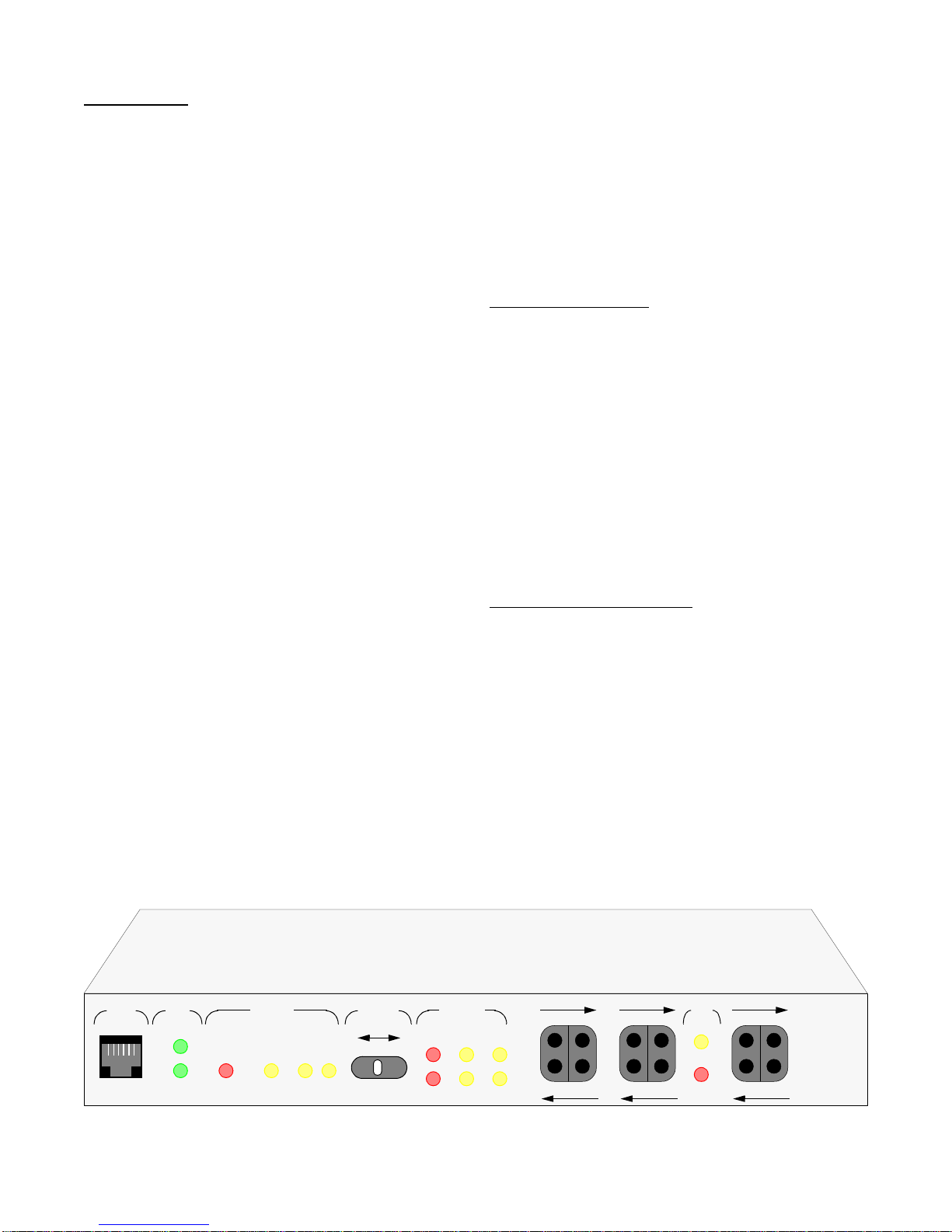
Front Panel Controls and Indicators ........................... 3-4
Supervisory Port .................................................. 3-4
Power Indicators .................................................. 3-5
Bypass Indicator .................................................. 3-5
Locked Indicator .................................................. 3-5
Status Indicators .................................................. 3-5
Manual Path Selector Switch ............................... 3-6
Path Status Alarm Indicators ............................... 3-6
Path Status LOS Indicators .................................. 3-6
Path Status Loop Indicators ................................. 3-6
Bantam Test Access Jacks ................................... 3-6
DTE Loop Indicator ............................................ 3-6
DTE Loss of Signal Indicator .............................. 3-6
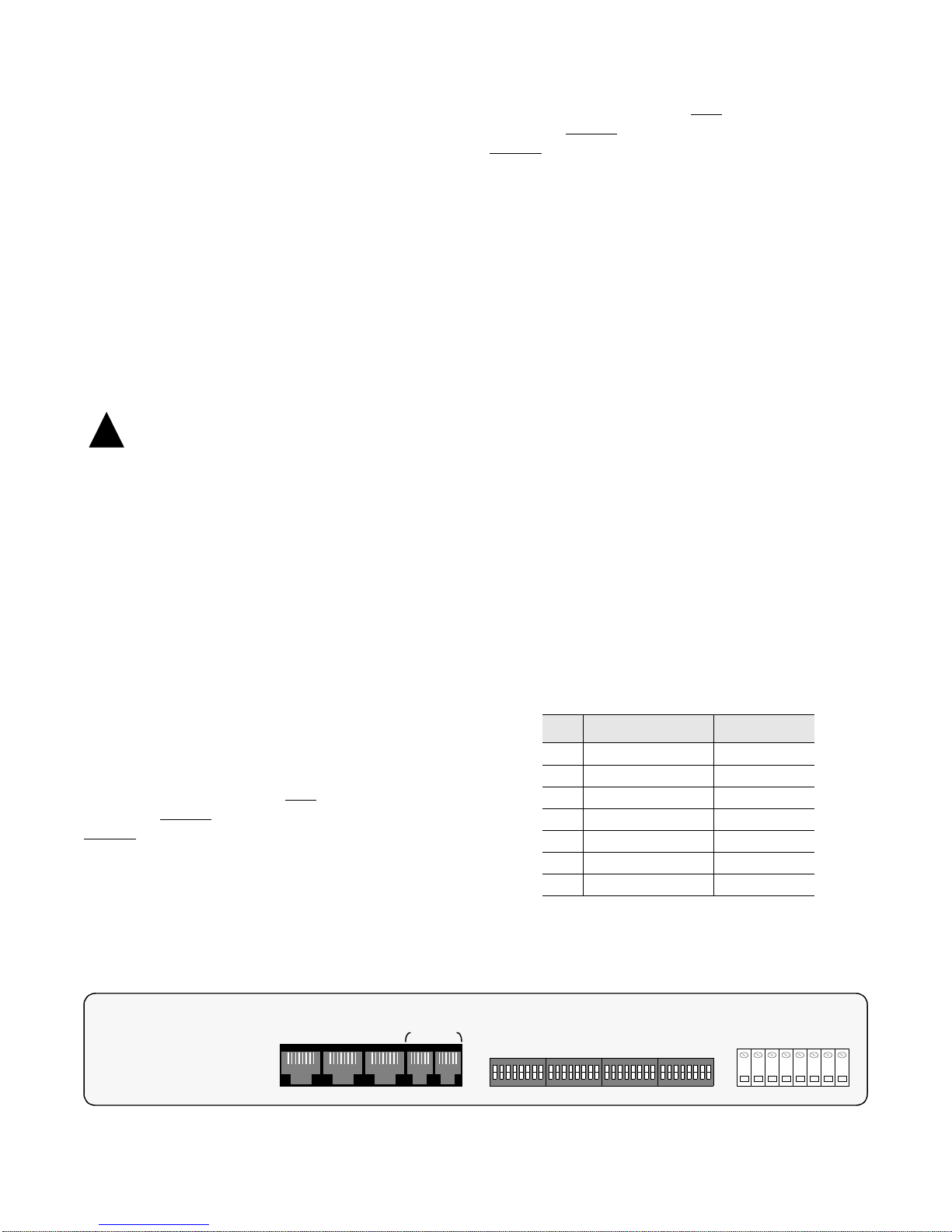
Rear Panel Connections .............................................. 3-7
COM Bus Connections ........................................ 3-7
Network T1 Connections ..................................... 3-7
DTE T1 Connection ............................................ 3-7
Screw Terminal Connections ............................... 3-7
Option Switch Functions ............................................ 3-8
LAPS Operation
Introduction ................................................................. 4-1
LAPS Installation ....................................................... 4-1
Screens and Menus ..................................................... 4-1
Common Screen Elements ................................... 4-1
Cursor Controls .................................................... 4-2
User Log On ........................................................ 4-2
Main Menu Screen ...................................................... 4-2
Circuit List Screens ..................................................... 4-3
Circuits in Alarm Screen ..................................... 4-3
Circuits in Test Screen ......................................... 4-3
Circuit List Screen ............................................... 4-3
Screen Manipulation ............................................ 4-3
Performance Screen ............................................. 4-4
Maintenance Screen .................................................... 4-6
Configuration Screen .................................................. 4-7
Utilities Screens .......................................................... 4-9
Loopback Operations .................................................. 4-10
Near CO Payload Loop ........................................ 4-10
CO Line Loop ...................................................... 4-10
CO Facility Loop ................................................. 4-11
CO Equipment Loop ............................................ 4-12
CPE Payload ........................................................ 4-12
CPE Line .............................................................. 4-12
CSU Loop ............................................................ 4-13
NET Loop ............................................................ 4-13
NPC Payload Loop .............................................. 4-13
BERT Testing ............................................................. 4-14
Table of Contents

Copyright
1996 TxPORT, All rights reserved. No part of this publication may be reproduced, transmitted, transcribed, stored
in a retrieval system, or translated into any language in any form by any means without the written permission of Tx-
PORT.
Reorder # 34-00228
2nd Edition, February 1996
TxPORT shall not be liable for errors contained herein or for incidental or consequential damages in connection with
the furnishing, performance, or use of this material. TxPORT reserves the right to revise this publication from time to
time and make changes in content without obligation to notify any person of such revision changes.
Contents of this publication may be preliminary and/or may be changed at any time without notice and shall not be
regarded as a warranty.
Documentation Disclaimer
TxPORT makes no representation or warranties of any kind whatsoever with respect to the contents hereof and specif-
ically disclaims any implied warranties of merchantability or fitness for any particular purpose.
Acknowledgment
The software used in the SNMP function of this product contains material derived from the following source:
Copyright 1989 by the Regents of the University of California. All rights reserved.
Redistributions in binary form must reproduce the above copyright notice, this list of conditions, and the following
disclaimer in the documentation and/or other materials provided with the distribution. All advertising materials
mentioning features or use of this software must display the following acknowledgment:
This product includes software developed by the University of California, Berkeley and its contributors.
Neither the name of the University nor the names of its contributors may be used to endorse or promote products
derived from this software without specific prior written permission.
This software is provided by the regents and contributors ‘as is’ and any express or implied warranties, including, but
not limited to, the implied warranties of merchantability and fitness for a particular purpose are disclaimed. In no
event shallthe regents or contributors be liable for any direct, indirect, incidental, special, exemplary, or consequential
damages (including, but not limited to, procurement of substitute goods or services; loss of use, data, or profits; or
business interruption) however caused and on any theory of liability, whether in contract, strict liability, or tort (in-
cluding negligence or otherwise) arising in any way out of the use of this software, even if advised of the possibility of
such damage.
Copyright/Liability

General 1-11558A APS
General
1.0 Introduction
The TxPORT 1558A APS (Automatic Protection Switch)
unit provides automatic T1 service restoration from a
degraded or failed T1 facility to a standby T1 facility. See
the ‘Operation’ chapter for a typical APS application.
Switching from the failed line (Path A or Path B) to the
standby (Path A or Path B) is based upon user definable
switching alarm thresholds (errored seconds, consecutively
severely errored seconds, loss of signal, loss of frame). The
1558A APS is fully compatible with all industry standard
APS equipment that complies with PUB 54017, 1991.
1.1 Design Highlights
The APS unit is designed so that it can be configured to sup-
port a wide variety of user applications. The key features
and functions are:
• Mission-Critical Automatic Protection Switching from a
Fail or Impaired T1 Facility to a Standby T1 Facility
• D4 or ESF Framing,
• AMI or B8ZS Line Coding
• Integral ESF CSUs (TR 54016 compliant)
• 24 Hour Performance History
• Revertive and Non-revertive Operation
• User-Definable Alarm Switching Thresholds
• Proactive Call-on-Alarm Reporting (requires manager)
• Desk Top or Rack Mount
• Redundant Power Configurations (AC or DC)
• Bantam Test Access Jacks
• Complies with AT&T 54017 Automatic Protection
Switching, 1991
• FCC, DOC, UL, and CSA Compliant
1.2 Specifications
T1 Network Interface
Line Rate: 1.544 Mbps
Framing: ESF
Line Code: AMI or B8ZS
DS1 Interface: +1 to -27 dB ALBO, 100 Ω(±5%)
Connector: RJ48 jack
Overvoltage Primary and Secondary lightning
Protection: fusing for line cross
ESF Mode: Pass/Block Facility Data Link
to/from Network
CPE (Equipment Interface)
Line Rate: 1.544 Mbps
Framing: D4 or ESF
Line Code: AMI or B8ZS
DSX Interface: DSX -1 to -6 dB (ALBO), RJ48
jack, 100 Ω(±5%), 0 to 655 ft.
Connector: RJ48 jack
A
SUPV PWR
B
STATUS
ABYPASS LOCKED B A
B
ALM LOS LP
A
SELECT
AUTO
PATH
B
STATUS
PATH
RX BRDG
TX BRDG
N
E
T
A
RX BRDG
TX BRDG
N
E
T
B
DTE
LOS
RX BRDG
TX BRDG
D
T
E
TxPORT
LP
1558A Automatic Protection Switch for customer premise
1558A

1558A APS1-2 General
ESF Mode: Pass/Block Facility Data Link
to/from DTE
Diagnostics
Line Loop: Signal regeneration only (bidirectional)
Payload Loop: Signal regenerated with new frame
synchronization, CRC6, and data.
Loop Activation Industry standard formats
and De-activation: (54016, 62411, T1-403)
Jack Access
Network Side: Bantam jacks Tx, Rx, & Bridging
for Transmit and Receive paths
DTE Side: Bantam jacks Tx, Rx, & Bridging
for Transmit and Receive paths
Alarms
Contacts: Normally Opened (NO) and
Normally Closed (NC)
Rating: 0.6A @ 125 VAC
2.0A @ 30 VDC
Power
Unit: Dual Inputs (Power A and Power B bus)
Range: -20 to -56 VDC, ≤150 mA, 10 W,
35 BTUs
Mechanical
Mounting: Desk, wall, or rack installation (comes
with 19” rack mount hardware)
Dimensions: 17.25" W, 1.75" H, 12" D
Weight: 5 lbs.
Environmental
Operating Temp: 0°to 50°C(32°to 122°F)
Storage Temp: -20°to 85°C(-4°to 185°F)
Humidity: 95% maximum (non-condensing)
Compatibility
PUB 54017: Automatic Protection Switching
Equipment, 1991
TR 62411: T1 interface and CSU specifications
PUB 54016: ESF requirements
UL 1549, Part 2: Electrical
Industry Listings
FCC Registration: FXKUSA-22709-XB-N
UL/CSA File Number: LR 62298
1.3 FCC Requirements
This equipment has been tested and found to comply with
the limits for a Class A digital device, pursuant to Part 15 of
FCC Rules. These limits are designed to provide reasonable
protection against harmful interference when the equipment
is operated in a commercial environment. This equipment
generates, uses, and can radiate radio frequency energy and
if not installed and used in accordance with the instruction
manual, may cause harmful interference to radio communi-
cations. Operation of this equipment in a residential area is
likely to cause harmful interference in which case the user is
required to correct the interference at his own expense.
Shielded cables must be used to ensure compliance with the
Class A FCC limits.
WARNING: Changes or modifications to this
unit not expressly approved by the party responsible for
compliance could void the user’s authority to operate the
equipment.
This device complies with Part 15 of the FCC rules. Opera-
tion is subject to the following two conditions:
1) This device may not cause harmful interference.
2) This device must accept any interference received,
including interference that may cause undesired operation.
Notice to Users of 1.544 Mb/s Service: The following
instructions are provided to ensure compliance with FCC
Rules, Part 68:
1) All direct connections to T1 lines must be made using
standard plugs and jacks.
2) The following information may be required by the local
telephone company when applying for leased line facilities:
!

General 1-31558A APS
3) If the unit appears to be malfunctioning, it should be
disconnected from the telephone lines until you learn
whether the source of trouble is your equipment or the tele-
phone line. If your equipment needs repair, it should not be
reconnected until it is repaired.
4) The unit has been designed to prevent harm to the T1
network. If the telephone company finds that the equipment
is exceeding tolerable parameters, they can temporarily dis-
connect service. In this case, the telephone company will
give you advance notice, if possible.
5) Under FCC rules, no customer is authorized to repair
this equipment. This restriction applies regardless of
whether the equipment is in or out of warranty.
6) If the telephone company alters their equipment in a
manner that will affect the use of this device, they must give
you advance warning so that you can have the opportunity
for uninterrupted service. You will be advised of your right
to file a complaint with the FCC.
7) The attached affidavit must be completed by the
installer.
8) In the event of equipment malfunction, all repairs
should be performed by our company or an authorized
agent. It is the responsibility of users requiring service to
report the need for service to our company or to one of our
authorized agents.
1.4 Canadian Emissions Requirements
This digital apparatus does not exceed the Class A limits for
radio noise emissions from digital apparatus set out in the
Radio Interference Regulations of the Canadian Department
of Communications.
NOTE: End users should use existing 48 VDC battery
sources or a CSA certified power supply.
Le present appareil numerique n’emet pas de bruits
radioelectriques depassant les limites applicables aux
appareils numeriques (de la class A) prescrites dans le
Reglement sur le brouillage radioelectrique edicte par le
ministere des Communications du Canada.
Port ID REN / SOC FIC USOC
P/N/12 - 00635 6.0 N 04DU9-BN
04DU9-DN
04DU9-IKN
04DU9-ISN
RJ48C
1.5 Warranty
TxPORT warrants each unit against defects in material and
workmanship for a period of five years from the date the
unit was shipped to the customer. If the unit malfunctions at
any time during the warranty period, TxPORT will repair, or
at TxPORT’s option, replace the unit free of charge.
The remedies listed herein are the users sole and exclusive
remedies. TxPORT shall not be liable for any indirect,
direct, incidental or consequential damages. The owner must
return the unit to the factory, shipping prepaid and packaged
to the best commercial standard for electronic equipment.
TxPORT will pay shipping charges for delivery on return.
The customer is responsible for mode and cost of shipment
to TxPORT. This warranty does not apply if the unit has
been damaged by accident, misuse or as a result of service
or modification by other than TxPORT personnel.
When returning the unit for warranty work, a Return Mate-
rial Authorization (RMA) number must be obtained from
customer service at the address/phone number given at the
end of this chapter. When calling TxPORT to obtain a
Return Material Authorization number or to arrange service,
please have the following information available:
• Model number(s) and serial number(s) for the unit(s).
• Reason for return and symptoms of problem.
• Warranty status (if known).
• Purchase order number to cover charges for out-of-war-
ranty items.
• Name and phone number of person we can contact if we
have questions about the unit(s).
• Mode of shipment required (second day air is the normal
mode of shipment for all returned material unless other-
wise specified).
As soon as TxPORT has the above information, the RMA
that must accompany the item(s) returned can be issued.

1558A APS1-4 General
1.6 Ordering Numbers
The 1558A is shipped from the factory with the following
standard items:
• The 1558A unit (the part number is F-1558-001A-1111)
• The 1558A reference manual
• 19" rack mount hardware
• Local Access PC software
• One PC to 1558A data interface cable
• AC to DC wall power transformer
• Three 10' RJ48 modular T1 cables
The following is a list of the standard and optional equip-
ment which may also be needed.
Part Number Equipment
F-1558-001A-1111 1558A unit with Dual Integral ESF CSU’s,
-20 to -56 VDC operation or
110 VAC operation.
6-3030-035-1 19" Rack Mount Hardware for 1558A.
Standard with 1558A unit.
6-3030-036-1 23" Rack Mount Hardware for 1558A.
Ordered as an option to the 1558A.
9-1558A-003-1 PC DOS Local Access software on 3.5”
Disk. Allows the user to access unit perfor-
mance, status, and configuration informa-
tion and to perform local loop testing.
9-1001-029-2 PC to 1558A data cable, 10' DB9 to 6-pin
modular. Standard with 1558A unit.
30-00087 110 VAC to -48 VDC (200 mA max.) wall
transformer unit, 10' power cable. Standard
with 1558A unit.
9-1001-004-010 RJ48 8-pin modular 10' cable. Three
cables come standard with the 1558A unit.
Contact the factory for additional cable
lengths and types.
F-1559-000-XXXX 1559 APSM Manager. Used for central site
management of one or more co-located
1558A units. Can be ordered as AC or DC
power, one or two internal modems, 19’ or
23’ rack hardware. Contact the factory for
additional information.
1.7 TxPORT Customer Service
Address: TxPORT
127 Jetplex Circle
Madison, Alabama 35758
Telephone: 800-926-0085 or
205-772-3770
Sales/Administration FAX: 205-772-3388
Manufacturing FAX: 205-772-8280
Customer Service Returns: 800-926-0085, ext. 227
Product Technical Support
Normal Hours - 8 a.m. to 5 p.m. Central, Monday – Friday
Telephone: 800-285-2755 or
205-772-3770
Emergency - Nights / Weekends / Holidays:
Telephone: 800-285-2755
E-Mail (Internet address): support@txport.com

Installation 2-11558A APS
Installation
2.0 General
Proper installation of the 1558A unit involves the following
key steps:
• Site Survey and Preparation
• Unpacking and Inspecting Equipment
• Equipment Mounting
• T1, Alarm, and Power Connections
• Setting Equipment Options
• Preservice Testing
The following paragraphs contain information and instruc-
tions to assist the user in preparing the 1558A for operation.
It is recommended that the user sequentially follow the site
preparation and unit installation steps described.
2.1 Site Preparations
The following site preparations should be performed before
starting installation of the 1558A APS unit. First, determine
the location of 1558A unit and perform the following:
A) Determine the distance from the APS unit to the AC
outlet, or if connecting to a DC external power source, the
distance to this source. The 1558A is shipped from the fac-
tory with a 110 VAC to -48 VDC wall transformer (10 ft.
cord). If external DC is being used, insure that 26 gauge
wire is on hand to wire the external DC power source to the
1558A unit. The maximum current draw of the 1558A is
≤80 milliamps at -48 VDC.
B) Determine the distance from the T1 facility demark and
the actual location of the 1558A. After determining dis-
tance, verify that the proper cable lengths and types have
been ordered to connect from the T1 demark to the 1558A
unit. The 1558A is shipped with three RJ48 modular T1
cable, 10 feet in length.
C) Normally, the provider of the T1 facility will provide
the required LBO setting (transmit signal level) required for
connection to the T1 facilities. This value should be used
when setting the 1558A LBO transmit values (0, 7.5, 15, or
22 db) in the 1558A unit. If the value cannot be obtained
from the provider, the LBO transmit values for Path A and
Path B should be set to 0 db.
D) Determine the distance between the 1558A unit and the
terminating DTE equipment. This distance will be used
when you set the DSX transmit LBO value for the DTE T1
port on the 1558A unit. The maximum distance that the
1558A DTE DSX receive will operate is 1,400 feet (using
ABAM cable, 26 gauge, shielded wiring).
E) Verify that the T1 line is operating properly before you
attempt to install the 1558A unit. Both of the T1 lines
should be checked for error free operation for at least 1 hour
to insure that they are performing error free.
F) If the unit is going to installed in a 19’ equipment be
rack, verify that there is enough rack space available in the
rack (requires 1.75 inches per 1558A unit). Four pan head
(type 12-24 x 1/2 inch) screws are provided for mounting
the unit. An optional 23” rack mount kit is available for
applications using this size rack.
G) Verify that no external CSUs (channel service units) are
installed at the location where the 1558A is being installed.
NOTE: The 1558A unit provides internal ESF CSU func-
tions and cannot operate properly if another CSU is also
co-located with the 1558A.
2.2 Unpacking and Inspection
This unit is carefully packaged to prevent damage in ship-
ment. Upon receipt, inspect the shipping container for dam-
age. If the shipping container or cushioning material is
damaged, notify the carrier immediately and make a nota-
tion on the delivery receipt that the container was damaged
(if possible, obtain the signature and name of the person
making delivery). Retain the packaging material until the
contents of the shipment have been checked for complete-
ness and the instrument has been checked both mechanically
and electrically.
If the contents of the shipment are incomplete or, if there is
mechanical damage or defect, notify TxPORT. If the ship-
ping container is also damaged, or the cushioning material
shows signs of stress, notify the carrier of the damage as
well as TxPORT. Keep the shipping materials for carrier’s
inspection. TxPORT will arrange for repair or replacement
without waiting for claim settlement.
2.3 Mounting
If the 1558A is to be installed in an equipment rack, simply
mount the 1558A in the equipment rack using the provided
mounting screws and rack mount adaptors (the 1558A can
be ordered with either 19” or 23” rack mount adaptors). If
the equipment is to be desk top installed, the user may
remove the provided rack mount adaptors and set the unit on
any flat surface. Once the equipment has been physically
located, the following rear panel wiring connections should
be performed.

1558A APS2-2 Installation
2.4 Wiring & Connections
There are several wiring connections that must be performed
to install the APS unit. The following paragraphs describe
how to attach the APS unit to the associated T1 lines, power
connections, alarm connections, and COM BUS connec-
tions. Figure 2-1 should be used as a reference for the fol-
lowing paragraphs concerning installation of the 1558A
APS unit.
2.4.1 Chassis Ground Connection
The 1558A unit should be connected to a good earth ground.
To connect ground to the unit, attach a 26gauge or larger
wire from the rear panel screw terminal labeled ‘GND’ to a
good earth ground.
Caution: Voltages in excess of 100 VDC may
be present on the T1 telecommunications lines. Before
connecting the APS unit to telecommunication lines,
insure that the rear panel screw terminal labeled ‘GND’
has been connected to a good earth ground.
2.4.2 DC Power Connections
The rear panel screw terminal labeled ‘-DC’ and ‘RTN’ are
used to connect -20 to -56 VDC to the 1558A. The 1558A
may be wired with redundant power inputs by wiring an
external source to both the PWR A and PWR B -DC/RTN
terminals. To connect power to the APS unit, perform the
following.
PWR A Wiring: Connect an external power source (-20 to
56 VDC) to the rear panel screw terminal labeled PWR A
‘DC’ and ‘RTN’. If using the provided AC to DC wall
power transformer, connect the RED wire to the ‘RTN’ ter-
minal, the BLACK wire to the ‘-DC’ terminal and the
GREEN wire to the ‘GND’ terminal.
PWR B Wiring: Connect an external power source (-20 to
56 VDC) to the rear panel screw terminal labeled PWR B
‘DC’ and ‘RTN’. If using the provided AC to DC wall
power transformer, connect the RED wire to the ‘RTN’ ter-
minal, the BLACK wire to the ‘-DC’ terminal and the
GREEN wire to the ‘GND’ terminal.
2.4.3 Alarm Connections
The 1558A has alarm contacts provided at the rear panel
screw terminals labeled ‘COMMON’, ‘NC’, and ‘NO’. The
alarm relay is operated when power is present to the 1558A.
To connect the APS alarm relay to an external customer
alarm surveillance system, perform the following:
• Connect a 26gauge wire to the rear panel screw terminal
labeled ‘COMMON’ to the external alarm system.
• Connect a 26gauge wire to the rear panel screw terminal
labeled ‘ALARM NO’ (normally open) or to ‘ALARM
NC (normally closed) to the external alarm system. Note
that the alarm relay is normally operated when power is
connected to the unit.
2.4.4 T1 Connections
All T1 lines are connected to the APS unit using modular 8-
pin RJ48 cables (three 10' cables come with the unit). Insert
the RJ48 connectors into the rear panel receptacles labeled
NET A, NET B, and DTE. Connect the other ends of the
cable to the appropriate T1 A and B facility equipment and
to the DTE equipment. The DTE port is not designed for
direct connection to a TELCO T1 facility. The modular pin
outs and their functions are shown in the following table.
!
Pin NET A & B, RJ48 DTE RJ48
1 Data In, Tip Data Out, Tip
2 Data In, Ring Data Out, Ring
3 Not Used Not Used
4 Data Out, Tip Data In, Tip
5 Data Out, Ring Data In, Ring
6 Not Used Not Used
7 Not Used Not Used
-20 to -56 VDC, 200 MA
S1
DTE COM BUSNET BNET A
IN OUT
GND
–VDC (A)
RTN (A)
–VDC (B)
RTN (B)
Alarm NO
Common
Alarm NC
S2 S3 S4
Figure 2-1 1558A Rear View

Installation 2-31558A APS
2.4.5 COM Bus Connections
The rear panel COM BUS connectors (IN/OUT) are used to
communicate to/from the optional APS 1559 site manager.
These connections are only used when a 1559 Network
manager is co-located with the 1558A(s). Bus connections
from the manager to one or more 1558A units is done in a
daisy chain fashion. That is, the COM BUS Out from the
1559 is connected to the COM BUS IN of the 1558A and
the COM BUS OUT of the 1558A is connected to the COM
BUS IN of the 1559. Physically, the connections to the
COM Bus IN/OUT are RJ11, 6-pin miniature modular
jacks. The function of the six pins associated with the jacks
are shown below.
2.5 Configuration Modes
Any time that the 1558A unit is initialized (power removed,
then reapplied), all key configuration data is read by the
1558A CPU and implemented based upon the particular
configuration boot mode options selected by the user. There
are four possible configuration boot modes:
• Configure/Boot from Switches (refer to Section 2.5.1).
• Configure/Boot from ROM (refer to Section 2.5.2).
• Configure/Boot from RAM (refer to Section 2.5.3).
• Configure/Boot from Manager. This requires the optional
1559 manager (refer to Section 2.5.4).
The following sections describe how to set up the 1558A to
boot using one of the above modes as well as other general
operating parameters.
NOTE: All factory default settings in this manual are
shown underlined.
2.5.1 Switch Configuration
After the equipment has been unpacked and inspected and
mounted, the next step is to configure the unit. All unit
options are set by the switch positions on four 8-position
DIP switches (S1, S2, S3 and S4) on the rear of the 1558A
unit. The 1558A is shipped from the factory with all option
switches in the OFF (factory default) position. The follow-
ing paragraphs briefly describe the 1558A option switches.
NOTE: After all of the option switches have been set to
the desired mode of operation, recycle the power to the
unit. At power up, the CPU will read and implement the
switch settings selected by the user.
Option Switch S1
This 8-position DIP switch is used to set the following unit
options:
• Block/Pass ESF data link configurations
• Regeneration or Pass CRC
• Master or Slave Card Operation
• Boot alarm parameters from ROM or RAM
• Boot general parameters from Switches, ROM, RAM, or
Manager
The following table describes the DIP switch settings con-
trolled by Switch S1.
Option Switch S2
This 8-position DIP switch is used to set the following unit
options:
• Alarm on Framing Errors
8 Not Used Not Used
PIN COM BUS IN COM BUS OUT
1 Not Used Not Used
2 Signal Ground Signal Ground
3 Data, output Data, Output
4 Data, input Not Used
5 Signal Ground Signal Ground
6 Not Used Not Used
Pin NET A & B, RJ48 DTE RJ48
Position Switch S1 Description
1OFF
= DTE/NET, Block Data Link
ON= DTE/NET, Pass Data Link
2OFF= NET/DTE, Block Data Link
ON= NET/DTE, Pass Data Link
3OFF
= DTE/NET, Regen. CRC
ON= DTE/NET, Pass CRC
4OFF
= NET/DTE, Regen. CRC
ON= NET/DTE, Pass CRC
5OFF
= Card Function, Slave
ON= Card Function, Master
6OFF
= ARM from ROM
ON= ARM from RAM
7,8 OFF,OFF = Boot from Switches
OFF,ON = Boot from Manager
ON,OFF = Boot from RAM
ON,ON = Boot from ROM

1558A APS2-4 Installation
• Alarm on Loss of Signal
• AMI/B8ZS Line Coding for DTE and NET
• CSU Functions Enabled/Disabled
• Path Revert, Enabled/Disabled
• DTE Framing ESF/D4 (NET framing is fixed as ESF)
The following table describes the DIP switch settings con-
trolled by Switch S2.
Option Switch S3
This is an 8-position DIP switch. It is used to set the 1558A
unit address ID for the NET A hardware and the NET B
hardware. Unique addresses must be optioned for each
1558A unit when multiple units are co-located and a 1559
Site Manager is being used. If no manager is being used, the
user should leave the DIP switches in the factory default
positions (all in the OFF or DOWN position). This config-
ures the unit for NET A address 1 and NET B address 2.
The following table indicates how to configure the address
settings for the first six 1558A units.
NOTE: When connecting to the SUPV port using the APS
local access software, the 1558A NET A/B addresses are
viewed as a single unit address and are displayed as 1.01
for addresses 1 and 2, 1.02 for addresses 3 and 4, etc.
Option Switch S4
This is an 8-position DIP switch. The following tables indi-
cate how to set the DIP switches for the various LBO and
DSX level settings. Note that S4-8 is not used (spare).
Positions 1 - 4 are used to set the LBO transmit level for the
NET A and NET B T1 signals. The factory default is 0 db
for the LBO settings.
Positions 5 - 7 are used to set the DSX signal level (in feet)
for the DTE port. The factory default is 0 to 133 feet for the
DTE DSX setting.
2.5.2 ROM Configuration
The 1558A may be configured to boot operational parame-
ters from the internal ROM (read only memory). To config-
ure the 1558A to boot from ROM, set S1-7 and S1-8 to the
ON position and S1-6 to the OFF position. With these set-
tings, the 1558A will always boot (at power up) the unit
configuration parameters from the internal ROM settings.
The ROM unit parameters are listed below:
• Block ESF data link, both directions
• Regenerate CRC6, both directions
• Slave Operation
• B8ZS line coding, both directions
• ESF framing, both directions
• Revert mode, disabled
• Availability timer set to 60 seconds
• Errored seconds set to 20
• Consecutively errored seconds set to 2
Position Switch S2 Description
1OFF
= Framing Errors, Enabled
ON = Framing Errors, Disabled
2OFF
= LOS, Enabled
ON= LOS, Disabled
3OFF
=NET/B, B8ZS
ON = NET/B, AMI
4OFF
=NET/A, B8ZS
ON = NET/A, AMI
5OFF
=DTE/B8ZS
ON = DTE/AMI
6OFF
= CSU Mode, Enabled
ON = CSU Mode, Disabled
7OFF
= Revert, Disabled
ON = Revert, Enabled
8OFF
= DTE, ESF
ON = DTE, D4
*APS Mgr.
Unit Pos. NET A/B
Address Pos
1Pos
2Pos
3Pos
4Pos
5 - 8
1.01 1/2 ON OFF OFF OFF OFF
1.02 3/4 ON ON OFF OFF OFF
1.03 5/6 ON OFF ON OFF OFF
1.04 7/8 ON ON ON OFF OFF
1.05 9/10 ON OFF OFF ON OFF
1.06 11/12 ON ON OFF ON OFF
LBO NET A NET B
S1 S2 S3 S4
0.0 DB OFF OFF OFF OFF
7.5 DB OFF ON OFF ON
15.0 DB ON OFF ON OFF
22.5 DB ON ON ON ON
DTE DSX Value S5 S6 S7
1 to 133 ft.* OFF OFF OFF
134 to 266 ft. OFF OFF ON
267 to 533 ft. OFF ON OFF
534 to 655 ft. ON OFF OFF

Installation 2-51558A APS
• Loss of frame set to Enabled
• Loss of signal set to Enabled
In addition to setting the ROM configuration options, the
user must also manually configure the following options:
• LBO transmit level setting for both NET A and NET B
• DSX transmit level/distance setting for the DTE T1 port
• 1558A unit address (if optional 1559 manager is installed)
2.5.3 RAM Configuration
The 1558A can be optioned to boot all alarm and operating
parameters from the battery backed RAM at power up. To
configure the 1558A for this mode of operation simply set
S1-7 to ON, and S1-8 to OFF. Note that the following unit
options must still be manually configured by the user:
• LBO transmit level setting for both NET A and NET B
• DSX transmit level/distance setting for the DTE T1 port
• 1558A unit address (if optional 1559 manager is installed)
2.5.4 Manager Configuration
The 1558A may be configured and controlled using the
optional 1559 APSM site manager. The manager, co-located
with one or more 1558A units (up to 56), provides both
local and remote access and control/alarm reporting to one
or more remote locations. When the 1558A has been config-
ured to ‘Boot from Manager’, the 1559 can access and
change all options except the following:
• 1558A Address
• 1558A LBO and DSX Levels
• Boot Mode (Switches, RAM, ROM, Manager)
To configure the 1558A to ‘Boot from Manager’, set S1-7
to OFF and S1-8 to ON. For additional information con-
cerning the use and operation of the 1559 manager, refer to
the TxPORT 1559 APSM reference manual.
Unit configuration of the 1558A APS is now complete. The
final steps to complete installation is to perform the 1558A
preservice testing steps describe in the following sections.
2.6 Preservice Testing
The preservice test checks the operational integrity of the
1558A unit. The local pre-service testing is made indepen-
dently of any DTE or T1 connections. The end-to-end test-
ing requires that the T1 facilities be connected to the unit
and that the user has a T1 test set. Figure 2-2 on page 2-6
illustrates the testing described in the following preservice
steps. Testing will verify:
• Path Integrity for Path A and Path B (local)
• Path Integrity for Path A and Path B (end-to-end)
The following T1 test equipment and miscellaneous cables
will be required to perform the preservice tests:
• Two T1 test sets (one required at each APS location)
• Two cables to go from the T1 test sets to the unit RJ48
DTE connectors at both ends.
Before proceeding, the user should read and understand the
background information presented in the following para-
graphs concerning the basic operation theory of an APS ser-
vice (also refer to Figure 3-1 on page 3-2).
APS service is different from “normal” point-to-point T1
service. The 1558A APS unit accepts a single source signal
from the attached DTE equipment, verifies signal density,
duplicates the signal, and then transmits it on two T1 lines
(Path A, Transmit and Path B, Transmit). This duplication
and dual transmission is also done at the far end APS equip-
ment (if applicable).
In addition to the unique transmitting function performed by
the APS, the unit also performs a unique receiving function.
There are two identical signals being received from two T1
lines by the APS equipment (Path A, Receive and Path B,
Receive). The 1558A constantly monitors both of these lines
for satisfactory signal performance. In the event that the
present active receive line exceeds an alarm value, the APS
will automatically switch the service from the failed receive
path to the standby receive path. The active receive signal is
the path connected to the DTE equipment.
Once a path has declared an alarm condition from Errored
Seconds, Consecutively Severely Errored Seconds, Loss of
Frame, or Loss Of Signal, it will not be available for service
until a 2-minute interval has been detected that was com-
pletely error free. At that time, the path alarm circuitry will
be reset and then the path will be ready to accept service.
2.6.1 Path A Preservice Testing
Perform the following test steps to verify that the 1558A can
run error free data from the DTE port to the NET A port and
back (local loop test). The test setup for performing this test
is depicted in Figure 2-2 on page 2-6.
1) Connect a T1 test set to the DTE RJ48 jack at the rear
of the 1558A unit. The test set should be configured to gen-
erate a T1 signal that matches the options previously set in
the 1558A unit (D4 or ESF, AMI or B8ZS) and configured
to supply clock to the 1558A.

1558A APS2-6 Installation
NOTE: If the 1558A DTE is configured for AMI opera-
tion, the test sets must be set up to generate either a 511,
2047, or 1:7 pattern. If the 1558A is configured for B8ZS
on the DTE and NET sides, any pattern may be used (511,
2047, 1:7, QRSS, 3:24, etc.). When sending a 1:7 pattern,
though, some T1 test sets inherently cause generation of a
yellow alarm condition.
2) Verify that there is no connection at the NET A jack.
3) Manually operate the front panel Path Select Switch to
the (A) position. This forces and locks the unit to Path A.
The following unit status LEDs associated with Path A test-
ing should be illuminated on the unit:
• Power A or B LED ON (green)
• Status ‘Locked’ LED ON (yellow)
• Status Path Active ‘A’ ON (green)
• The Path Status, Alarm A (red) LED may be ON or OFF
depending on the alarm timer setting (0 to 900 seconds)
configured in the 1558A.
4) The 1558A unit is now looped back to the DTE port
and the T1 test set should be running in sync and error free.
If not, verify that the T1 test set framing and line coding set-
ting match the settings configured in the 1558A.
The 1558A unit is now looped back to the DTE port and the
T1 test set should be indicating that it is detecting pattern
sync and running error free. If “yes” proceed to Path B,
Preservice Testing. If “no”, verify that Steps 1 - 4 have been
completed properly. If there is still a problem, perform the
following:
• Loop the T1 test set to itself and verify that test set runs
error free.
• Verify that the T1 test set is properly configured to operate
with the options set in the 1558A (D4 or ESF, AMI or
B8ZS).
• Also verify that the T1 test set is configured to supply
clock (internal).
S1
DTE COM BUSNET BNET A
IN OUT
S2 S3 S4
Bantam Patch Cord
Path NET A
Figure 2-2 Local 1558A Test Diagram, Path A and Path B
RX BRDG
TX BRDG
N
E
T
A
RX BRDG
TX BRDG
N
E
T
B
RX BRDG
TX BRDG
D
T
E
Bantam Patch Cord
Path NET B
RX BRDG
TX BRDG
N
E
T
A
RX BRDG
TX BRDG
N
E
T
B
RX BRDG
TX BRDG
D
T
E
T1 Test Set Configured for:
Framing - D4 or ESF
Line Code - AMI or B8ZS
Clocking - Internal
Pattern - QRSS, 1:8, 3:24, etc.

Installation 2-71558A APS
2.6.2 Path B Preservice Testing
Perform the following test steps to verify that the 1558A can
run error free data from the DTE port to the NET B Port and
back (local loop test). The test setup for performing this test
is depicted in Figure 2-2.
1) Connect a T1 test set to the DTE RJ48 jack at the rear
of the 1558A unit. The test set should be configured to gen-
erate a T1 signal that matches the options previously set in
the 1558A unit (D4 or ESF, AMI or B8ZS) and configured
to supply clock to the 1558A (internal).
NOTE: If the 1558A DTE is configured for AMI opera-
tion, the test sets must be set up to generate either a 511,
2047, or 1:7 pattern. If the 1558A is configured for B8ZS
on the DTE and NET sides, any pattern may be used (511,
2047, 1:7, QRSS, 3:24, etc.). When sending a 1:7 pattern,
though, some T1 test sets inherently cause generation of a
yellow alarm condition.
2) Verify that there is no connection at the NET B jack.
3) Manually operate the front panel Path Select Switch to
the (B) position. This forces and locks the unit to Path B.
The following status LEDs associated with Path A testing
should be illuminated on the unit:
• Power A or B LED ON (green)
• Status ‘Locked’ LED ON (yellow)
• Status Path Active ‘B’ ON (green)
• The Path Status, Alarm B (red) LED may be ON or OFF
depending on the alarm timer setting (0 to 900 seconds)
configured in the 1558A)
4) The 1558A unit is now looped back to the DTE port
and the T1 test set should be running in sync and error free.
If not, verify that the T1 test set framing and line coding set-
ting match the settings configured in the 1558A.
The 1558A unit is now looped back to the DTE port and the
T1 test set should be indicating that it is detecting pattern
sync and running error free. If so, the preservice local test-
ing is complete. If not, verify that Steps 1 - 3 have been
completed properly. If there is still a problem, perform the
following:
• Loop the T1 test set to itself and verify that test set runs
error free.
• Verify that the T1 test set is properly configured to operate
with the options set in the 1558A (D4 or ESF, AMI or
B8ZS).
• Also verify that the T1 test set is configured to supply
clock (internal).
2.6.3 Results
The stand-alone preservice testing verifies the operational
integrity of the 1558A. If either Path A or Path B failed, but
not both, and the options have been verified, the user should
contact the factory for additional assistance (refer to the
‘General’ chapter).
2.6.4 End-to-End Pre-Service Testing
The following paragraphs describe preservice APS testing
of the 1558A when it is initially connected to the T1 facili-
ties (Path A and Path B) and is configured with another
1558A APS at the far end.
After completing the stand-alone preservice test procedures,
the 1558A is ready to be connected to the Path A and Path B
T1 facilities for verification of end-to-end operation. These
test procedures will verify the following:
• End-to-End Error Performance of Path A
• End-to-End Error Performance of Path B
The following steps assume that there is a near end unit and
a far end unit and a technician with a T1 test set located at
both the near and the far end of the APS service.
1) Attach the Path A and Path B T1 facilities to the
respective NET A and NET B modular jacks at the rear of
the unit (both near and far locations).
2) There are four basic methods of configuring the 1558A
which directly impact the settings used in the test sets. Con-
figure both T1 test sets per one of the following scenarios:
• 1558A DTE side configured for D4 framing and T1 NET
sides configured for ESF.
• 1558A DTE side configured for ESF framing, and NET
sides configured for ESF.
• 1558A DTE side configured for AMI line coding and NET
sides configured for B8ZS line coding.
• 1558A DTE side configured for B8ZS line coding and
NET sides configured for B8ZS line coding.
NOTE: If the 1558A DTE is configured for AMI opera-
tion, the test sets must be set to generate either a 511,
2047, or 1:7 pattern. If the 1558A is configured for B8ZS
operation, any pattern may be used (511, 2047, 1:7,
QRSS, 3:24, etc.). When sending a 1:7 pattern, though,
some T1 test sets inherently cause generation of a yellow
alarm condition.
Make sure that one of the test sets is set for internal and that
the other is set for recovered clock.
3) Once the test sets have been configured similar to the
1558A units, connect the near and the far test set to the
DTE RJ48 jack located at the rear of the 1558A units.

1558A APS2-8 Installation
4) Operate the Service Select switch on the 1558A to the
Path A position at both the near and far 1558A units. This
forces both units to use Path A as the receive signal source.
Once this is done, both test sets should indicate pattern sync
at both the near and far locations. Run test for 15 minutes.
Test should be error free at both ends. If errors are detected,
repeat test for another 15 minutes. If errors are still detected,
a problem exists in the T1 facility. Refer problem to appro-
priate channels for resolution.
5) Operate the Service Select switch on the 1558A unit to
the Path B position at both the near and far 1558A units.
This forces both units to use Path B as the receive signal
source. Run test for 15 minutes. Test should be error free at
both ends. If errors are detected, repeat test for another 15
minutes. If errors are still detected, a problem exists in the
T1 facility. Refer problem to appropriate channels for reso-
lution.
6) After completing the end-to-end testing of both Path A
and Path B, connect the DTE equipment.
This completes the end-to-end operational check for the
1558A. The unit is now ready to support automatic protec-
tion switching.
2.7 Bypass Test
The 1558A supports a “bypass” mode of operation which
allows the NET A path to be physically connected directly
to the DTE port. In this mode, all active electronics are
removed. The only components in the transmission paths
while the BYPASS mode is active are line protection com-
ponents and test access jacks. The BYPASS mode of opera-
tion is automatically implemented when either of the
following occurs:
• Power is removed from the unit (external power failure)
• CPU detects an internal operational fault. If this occurs,
the front panel ‘BYPASS’ LED (red) will be on to indicate
that the 1558A has detected a unit fault and that it is now
operating in the BYPASS mode.
During BYPASS, their is no signal regeneration. Typically,
the transmit and receive levels to/from the T1 demark and
the terminating DTE will perform satisfactorily. However,
there is the potential that the signal levels will be unusable
by either the DTE equipment or by the T1 facility equip-
ment.
To verify that the BYPASS mode will work in your particu-
lar application, perform the following steps:
1) First, end-to-end testing must be complete. If so, pro-
ceed to step 2.
2) Remove the external power from the 1558A unit. Note
that all front panel LED indicators go off. The 1558A will
automatically implement the BYPASS mode which connects
the NET A T1 facility directly to the DTE port.
3) With the power still off, verify that the DTE equipment
is operating. If so, this application will support the BYPASS
mode. If the DTE is not operating, this means that the signal
levels either to the DTE or from the DTE are to low for
proper operation without signal regeneration. If this is the
case, then BYPASS mode will not be viable for this particu-
lar application.
NOTE: The bypass mode requires that the DTE port and
the DTE equipment must be set for the same framing and
line coding as the T1 facility (ESF and AMI or B8ZS).

Operation 3-11558A APS
Operation
3.0 Introduction
The 1558A provides the capability to automatically switch
from a “defective” T1 service to a standby facility. This
capability minimizes any actual service outage to the cus-
tomer. Typically, switching from the active to the standby
path is transparent to the user (voice “hitless” with minimal
impact on data services). The 1558A Automatic Protection
Switch (APS) equipment is compatible with AT&T TR
54017, Addendum, February, 1991. When the 1558A is con-
figured for internal ESF CSU operation, it is fully compati-
ble with AT&T TR 54016 ESF CSU requirements.
3.1 Applications
APS T1 protection service (per TR 54017) is either provided
by a Common Carrier (AT&T or MCI, etc.) or by the cus-
tomer. When a Common Carrier provides the service, APS
equipment is installed in the central office and at the cus-
tomer premise location(s). In the case of customer provided
APS, the customer installs a 1558A at both ends of the mis-
sion-critical service. Figure 3-1 on page 3-2 depicts some
of the more common APS applications.
TxPORT APS equipment must be installed in pairs (one
TxPORT unit at one end of the service and another unit at
the other end of the service). One unit of the pair must be
configured for ‘Master’ mode and the other as Slave mode.
3.2 General Operation
The 1558A constantly monitors the status and quality of the
path signal (A and B) received on both the active access
path and standby access path. In general, the status and qual-
ity of the signal is based on the ESF parameters described in
Section 3.1 of TR 54016 and additional parameters
described in this document and in TR 54017, 1991. If the
performance of the active path is determined to be impaired,
the protection switching equipment will automatically select
the standby access path if that path is ready for service (not
in an alarm or a maintenance state). The level of impairment
at which a transfer is accomplished is dependent upon the
alarm threshold values set in the equipment.
Following a switch, the former standby access path becomes
the active path. The 1558A continues to monitor both of the
incoming data streams after a switch has occurred. If both
active and standby access paths exceed their specified
thresholds, service will be maintained on the currently
active access path.
The switch from the active to the standby path is completely
independent of any external equipment. Switching from an
active path to a standby path only involves the receive paths
(Path A and Path B), not the transmit paths.
3.2.1 Revertive and Non-Revertive Switching
The default configuration of the 1558A APS provides non-
revertive protection. Specifically, this means that service,
when transferred to the standby path, remains on the new
path until its performance degrades past the threshold set-
tings. This is in contrast to the optional revertive mode
which returns service to the default path when it has
returned to a minimal level of error free performance.
3.2.2 Default Power-Up Path
The desire for geographically diverse routing may also
result in diversity in the medium of transmission (copper,
fiber, microwave, etc.). Certain media have higher intrinsic
performance criteria and are therefore the service of prefer-
ence. To accommodate this preference, on power up, the
1558A APS unit forces the Path A as the active path.
3.2.3 Loss of Signal / Loss of Frame
When a loss of signal is detected from the DTE side, the
1558A units generates an AIS signal towards the facility
paths (Paths A and B).
When a LOS (Loss Of Signal) is detected on the active path
from the facility side of the APS, the 1558A will immedi-
ately switch the service to the standby facility (assuming
that the standby path is not in an alarm or a maintenance
state and the LOS alarm is enabled). If the standby path is in
an alarm state, the service will remain on the failed path
until the alarm condition clears on the standby path.
Optionally, in the event that there is a signal present but it is
so impaired that it results in a LOF (Loss Of Frame), the
1558A shall immediately switch after detecting 32 consecu-
tive framing errors (approximately 93 milliseconds) to the
standby path (assuming that it is not in an alarm or a mainte-
nance state and the LOF alarm is enabled).
3.2.4 Bipolar Violations
The 1558A APS units will not allow BPV
(Bipolar Violations) in the DS-1 data stream unless they are
used for B8ZS (Bipolar 8 Zero Substitution) encoding for
clear channel capability. Where used, the B8ZS code will be
employed to prevent the generation of an all zero octet.

1558A APS3-2 Operation
1
5
5
8CO #1 CO #2
1
5
5
7
1
5
5
7
1
5
5
8
DTE
T1, A
IXC Network
CO #2CO #1
IXC Network T1 ACCESS
1
5
5
7
1
5
5
7
Master
Slave Slave
Master
T1, B
T1, A
T1, B
T1, A
T1, B
IXC Local Loop APS application, both ends
IXC Network APS application
Master Slave
DTE
DTEDTE T1 ACCESS
Telco and/or IXC Network
1
5
5
8
1
5
5
8
T1, A
T1, B
Customer Provided end-to-end APS Application
Master Slave
DTEDTE
T1, A
T1, B
Figure 3-1 Typical APS Applications
3.2.5 CSU Loopbacks
Two ESF CSU loopbacks are provided in the 1558A unit
(CSU Line Loop and CSU Payload Loop). These loops can
be activated and deactivated by TR 54016 ESF messages, or
Inband per TR 62411. To insure maximum service availabil-
ity, the following special conditions shall be applied to CSU
loopback actuation via the ESF data link messages:
• A CSU Line Loop or Payload can’t be activated on the
active path.
• If the CSU Line Loop or Payload Loop activate signal is
received by both paths simultaneously, no change of LB
state shall occur, regardless of their current states.
The “one-way” protection characteristic of the APS can
result in split-service operation. That is, service from the
1558A near APS to the 1558A far APS via one access path
while the 1558A far APS to the 1558A near APS service is
on the other access path. This is desirable to minimize ser-
vice disruptions. However, normal maintenance and fault
isolation techniques can’t be carried out while service is
being delivered in the split mode. Service to and from the
APS must be forced to a common access, either manually or
via maintenance message, before the standby path LB can
be activated.
3.2.6 Forced/Locked Capability
A manual path select control is provided on the APS which
selectively forces service to either Path A or Path B and
effectively inhibits the other path from accepting service.
The manual service select control supersedes all automatic

Operation 3-31558A APS
transfers and forces the path not inhibited to carry the ser-
vice, regardless of its status or condition.
3.2.7 APS Switching Time
Two times are of significance in specification of the APS
protection switching function. The first is the latency period
between the point when the switching criteria is satisfied on
the active access path and the point at which restoration
occurs on the standby access path. This time is less than 50
milliseconds.
The second is the duration of the switching transient event
associated with physically moving service from the active to
the standby access path. The 1558A APS can complete the
transition from active to standby path within 1 bit time.
The decision to transfer service from the active path to the
standby path, and vice-versa, is based on a priority system,
where the highest priority condition that satisfies a transfer
controls, regardless of the conditions in lower priorities.
• Priority 1 – LB Status:
If the standby path’s LB is activated, then service shall
remain on the active path.
• Priority 2 – Failed Status:
If the standby path is in a failed state then service shall
remain on the active path. A failed state could be a result
of excess ES, CSES, LOS, or LOF.
• Priority 3 – Error Event Threshold Criteria:
This level of transfer is based on the occurrence of 1 sec-
ond events within the current 15 minute interval as
described in the TR 54017 Addendum.
Each error event requires storage for the following values:
threshold setting, current count, and a service transfer flag.
The threshold setting for the events (ES and CSES) may
range from 1 to 900 seconds. Transfer of service is based
only on these events.
If the threshold of an event is 0, that event is inactive and is
not a criterion for transfer of service. The current count tal-
lies the total number of error event seconds within the cur-
rent 15 minute interval. This count is reset at the beginning
of a new 15 minute interval.
The service transfer flag is set for the event that causes a
transfer of service. It allows the cause of the service transfer
to be determined even after the current count has been reset
at the beginning of a new interval. This flag is reset when a
service transfer acknowledgment message is received, which
is described in the next section.
3.2.8 APS Switching Parameters
The 1558A unit switches from the active line to the standby
line based upon user definable alarm parameters. The alarm
performance parameters that can configured by the user are
Errored Seconds, Consecutively Severely Seconds, Loss of
Signal, and Loss of Framing. These alarm parameters and
their definition are described below.
Errored Seconds (ES) - The user can define that the 1558A
switches from the active line to the standby line when a cer-
tain number of errored seconds have been detected during
the current 15 minute performance interval (900 seconds).
The ES threshold can be set from 0 (setting this parameter to
a zero value disables ES switching) to 900 seconds. The
1558A is configured at the factory with 20 errored seconds
as the default errored second value. The definition of an ES
is a second containing one or more CRC errors.
Consecutive Severely Errored Seconds (CSES) - The user
can define that the 1558A switches from the active line to
the standby line when a certain number of Consecutive
Severely Errored Seconds have been detected during the
current 15 minute performance interval (900 seconds). The
CSES threshold can be set from 0 (setting this parameter to
a zero value disables CSES switching) to 900 seconds. The
1558A is configured at the factory with 2 consecutive
severely errored seconds as the default CSES value. The
definition of a CSES is when two or more consecutive SES
have been detected (note that CSES are transparent to the
boundary between 15 minute intervals). A severely errored
second is defined as a second containing 320 or more ESF
errors.
Loss of Signal (LOS) - The user can define that the 1558A
switches from the active line to the standby line when a loss
of signal state has been detected. The 1558A is shipped
from the factory with loss of signal parameter enabled. The
definition of a loss of signal is when the receive signal from
the network contains ≥175 consecutive bit intervals contain-
ing all zeros (no pulses). The condition will be cleared when
one or more intervals contain a one.
Loss of Frame (LOF) - The user can define that the 1558A
switches from the active line to the standby line when a loss
of frame error state has been detected. The 1558A is shipped
from the factory with the loss of frame parameter enabled.
An LOF alarm condition occurs when 32 or more consecu-
tive ESF frames contain frame bit errors.
When the current count of either ES or CSES is greater than
or equal to the threshold setting or when a LOS or LOF (if
enabled) is detected, the service shall be transferred from
the active path to the standby path as long as the standby
path is available (not in an alarm state or in a looped state).
A requirement for the standby path to be available is that the
timer circuitry, described below, is not active and a LOS or
LOF condition does not exist.

1558A APS3-4 Operation
3.2.9 Line Availability Timer
The line availability timer is used to quantify when a path is
eligible to accept service.Line availability is determined by
the APS by observing a defined window of time in which no
active error events have occurred. The APS line availability
timer can be set to any value from 0-900 seconds. This
value represents the minimum amount of time, free of active
error events, that must expire before this path is declared as
ready to accept service. The factory default setting for the
line availability timer is 60 seconds.
The line availability timer requires storage for the timer set-
ting and the active timer count. If the timer setting is 0, the
timer circuitry is disabled and the path is always available
for service, assuming that there are no active alarm condi-
tions present. If the timer setting is set to a value ranging
from 1 to 900 seconds and a service transfer takes place, the
standby unit initializes the active timer count to the timer
setting. When the timer expires, this standby path becomes
available for a service transfer. This timed period must be
free of errors for all active events. If an error occurs, the
active timer count is reset.
When operated in the optional revertive mode, the path
availability timer serves to force restoration of service back
to the default access, Path A. That is, when service is
switched from Path A, it will remain on the standby path
(Path B) only until Path A’s availability timer expires. The
factory default is Revert set to OFF.
3.2.10 Status and Performance Information
The current status and performance parameters are stored in
the internal registers of the 1558A. Access to this informa-
tion is via the 1559 APSM site manager (optional) or the
LAPS (local access protection switch) PC software. The
LAPS software is shipped with each 1558A unit.
The following information can be viewed by the user using
either the 1559 APS Site Manager or the provided APS
Local Access DOS Software.
• This path is currently carrying the service.
• This path is currently in a failed state.
• This path is currently in an inhibit state.
• The LB of this path is currently activated.
• The other path is currently in a failed state.
• The other path is currently in an inhibit state.
• The LB of the other path is activated.
• The manual locked control state.
• Current status
• Current interval Occurrences
• Current interval Duration
• Current Interval Timer
• Occurrences - Intervals, 1 through 96
• Duration - Intervals, 1 through 96
• Valid Intervals Total
• Occurrences, 24-hour value
• Duration, 24-hour total
• 30-day switch occurrence history
3.2.11 Configuration Modes
Any time that the 1558A unit is initialized (power removed,
then reapplied), all key configuration data is read by the
1558A CPU and implemented based upon the particular
boot mode options selected by the user (see Installation Sec-
tion for additional information). The four possible BOOT
mode configurations are described below:
1) Boot from Switches - At power up, the 1558A CPU
reads the values set at the rear panel option switches and
configures the unit per those switch settings.
2) Boot from Manager - At power up the CPU sends a
message to the 1559 APS manager for a download of 1558A
unit configuration information. Note that this mode requires
that a 1559 site manager be installed.
3) Boot from RAM - At power up, the 1558A CPU reads
the unit configuration from the battery backed RAM data.
4) Boot from ROM - At power up, the 1558A CPU reads
the factory firmware default values from ROM. The factory
default ROM configuration option settings are:
• Block data link, both directions
• Regenerate CRC6, both directions
• Slave operation
• B8ZS line coding, both directions
• ESF framing, both directions
• Revert mode, disabled
• Availability timer set to 60 seconds
• Errored seconds set to 20
• Consecutively errored seconds set to 2
• Loss of frame set to enabled
• Loss of signal set to enabled
3.3 Front Panel Controls & Indicators
The front panel of the APS unit contains several LED indi-
cators, a SUPV access port, a path select switch, and several
bantam test access jacks. The following paragraphs briefly
describe the operation of these items (refer to Figure 3-2
and the 1558A Configuration at the end of this manual).

Operation 3-51558A APS
3.3.1 Supervisor Port
The front panel SUPV port allows the user to connect to the
1558A via a PC running the supplied APS LAPS (Local
Access protection software) application. This user interface
software allows the user to gain access to the unit configura-
tion data, unit status, unit performance, and perform local
and remote loopback testing.
Electrically, the SUPV port is RS232 and the data format is
19.2 Kb, asynchronous. The cable used to connect the PC to
the SUPV port is a DB9 (female) to 6-pin modular cable.
This cable is provided with the 1558A unit. The pin func-
tions for the SUPV port are shown in the following table.
3.3.2 Power Indicators
The 1558A has two green power LED indicators (Power A
and Power B). One or both of the indicators will be ON
when a nominal power source of -20 to -56 VDC is present
on the rear panel PWR A and PWR B screw terminals,
respectively. The indicator(s) will be OFF if the power is not
present at the respective power screw terminals. Only one
power input is required to operate the unit. If power redun-
dancy is crucial, both the Power A and Power B inputs
should be wired to an external -20 to -56 VDC source. The
1558A unit is shipped with a single 110 VAC to -48 VDC
wall power unit.
3.3.3 Bypass Indicator
The red BYPASS LED indicates whether or not the 1558A
is presently in a BYPASS mode of operation. The LED will
be ON if the unit has detected a CPU watchdog operational
fault. The LED will be OFF under normal operation.
When active, the BYPASS mode connects the NET A T1
facility directly to the DTE port. In this mode, all of the
active electronics are bypassed. That is, the only elements in
the path are passive line protection circuitry components for
the NET A port and the DTE port. During BYPASS opera-
tion, the 1558A acts only as a passive device and does not
perform any signal regeneration functions.
Activation of the BYPASS mode occurs when either the
CPU watchdog timer circuitry is defective (indicates a CPU
or software problem) or when power is removed from the
unit. The BYPASS mode is terminated when either the CPU
watchdog circuitry is determined to be normal or when
power is restored to the unit.
3.3.4 Locked Indicator
The user can manually force and lock either the A or B T1
path as the active path by moving the PATH SELECT switch
from the AUTO position to either the A or B Path Select
positions. This action will force the 1558A to use the
selected path. Also, the 1558A is now manually locked to
this path and will not switch from it, even if the selected
path is in a failed state or subsequently fails. When the
1558A has been manually forced to either the A or B PATH,
the amber LOCKED LED indicator will be on. Moving the
PATH SELECT switch back to the AUTO position will turn
off the LOCKED LED and restore normal APS operation.
Caution: Placing the 1558A in a manually locked
mode prevents the unit from performing automatic pro-
tection switching.
Pin SUPV Port Wiring
1 Not Used
2 Ground
3 Data, Out
4 Data, In
5 Ground
6 Not Used
Figure 3-2 1558A Front View
A
SUPV PWR
B
STATUS
ABYPASS LOCKED B A
B
ALM LOS LP
A
SELECT
AUTO
PATH
B
STATUS
PATH
RX BRDG
TX BRDG
N
E
T
A
RX BRDG
TX BRDG
N
E
T
B
DTE
LOS
RX BRDG
TX BRDG
D
T
E
TxPORT
LP
1558A
Table of contents