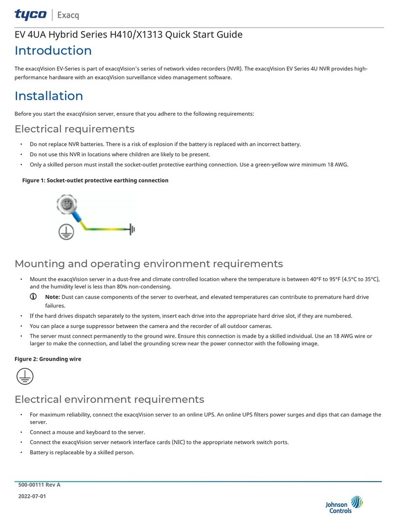
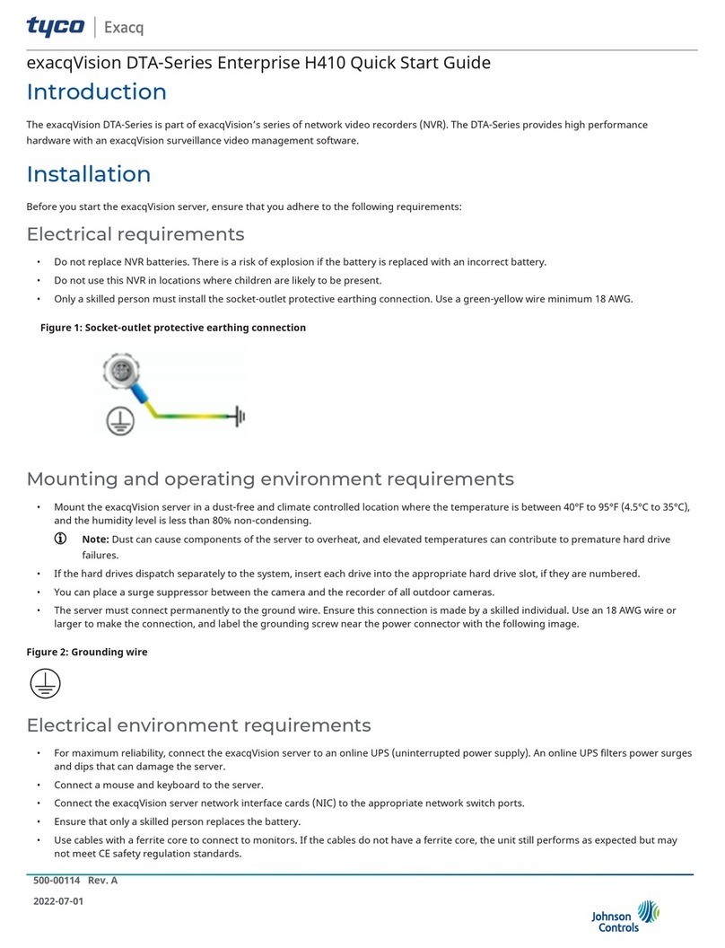
Tyco Exacq A Series User manual

Introduction
The exacqVision A-Series is part of exacqVision’s series of network video recorders (NVR). The exacqVision A-Series, IPS 2UA and F2A provide high
performance hardware with an exacqVision surveillance video management software. The F2A IP model features greater storage capacity, an
optional RAID 5 disk configuration, greater video storage rate, greater number of hard drives, and a wider range of operating systems.
Installation
Before turning on the exacqVision A-Series server, ensure that you meet the following requirements:
Mounting and operating environment requirements
• Mount the exacqVision server in a dust-free, and climate controlled location where the temperature is between 40°F to 95°F (4.5°C to 35°C),
and the humidity level is less than 80% non-condensing.
Note: Dust can cause components of the server to overheat, and elevated temperatures can contribute to premature hard drive
failures.
• If the hard drives dispatch separately to the system, insert each drive into the appropriate hard drive slot, if they are numbered.
• The server must connect permanently to the ground wire. Ensure that you use an 18 AWG wire or larger to make the connection, and that
you label the grounding screw near the power connector with the image in Figure 1. Ensure this connection is made by a skilled individual.
Figure 1: Grounding wire
Electrical environment requirements
• For maximum reliability, connect the exacqVision server to an online UPS. An online UPS filters power surges and dips that can damage the
server.
• Connect a mouse and keyboard to the server.
• Connect the exacqVision server network interface cards (NIC) to the appropriate network switch ports.
• Battery is replaceable by a skilled person.
• Use cables with ferrite core for connecting to monitors. If the cable does not have a ferrite core, the unit still performs as expected but may
not meet CE safety regulation standards.
Network connection requirements
• If the video surveillance system does not have a physically isolated network, connect all IP cameras and one server NIC to a dedicated
camera VLAN.
• Install the camera manufacturer’s software on a PC in this subnet, or configure the router to connect a client computer with the camera
subnet. For information on how to configure the network, see Configuring the server.
• This VLAN configuration reduces the chances of network traffic conflicts and unauthorized access to the cameras.
2021-09-15
500-00082 E
A-Series IPS 2UA/F2A Quick Start Guide

Initial startup
When you start the exacqVision server for the first time, create a user name and password for the operating system, then create a root user
name and password for the Enterprise Manager.
1. Turn on the exacqVision server.
2. Create a user name and password for the operating system when the logon dialog box appears. Configure operating system settings as
required.
3. If prompted, log on again to the operating system with the user name and password you just created.
4. When you log on, an exacqVision dialog box appears on the desktop. Create the exacqVision admin user name and password.
Note: This is not the same as the credentials you created to log on to the operating system. Use these credentials to log on to the
exacqVision Server.
Configuration
After you turn on the exacqVision server, you must log on to the administration account with administrator credentials.
Enter the following credentials depending on the platform:
Linux
Enter the username Administrator and the password admin256.
Windows
Follow the instructions to configure certain settings such as the time zone and language. Enter a new administrator’s password when
prompted. The password must contain a minimum of 8 characters, use a combination of numbers and uppercase letters. It is important to
remember the password.
Configuring the server
To configure the exacqVision server, complete the following steps:
1. Turn on the server.
2. Open the exacqVision client application.
3. From the navigation tree, select System Setup, and select the Network tab.
4. Choose one of the following options:
- If you install the server on a network that uses static IP addressing, select Static and enter the IP address.
- If you install the server on a network using DHCP, select Dynamic. If the information does not automatically configure, contact
your network administrator.
5. Click Apply.
What to do next:
Repeat this procedure for any additional network ports. For more information on configuring the server, refer to the exacqVision Start User
Manual.
Configuring the client
1. Start the exacqVision client application
2. When the local client is launched for the first time, enter the exacqVision user name and password created during initial startup.
3. Verify that the server appears in the Systems list with a status showing Connected.
Note:
If the server does not connect, but you can confirm the server's ability to connect, check for anti-virus software on the remote client
machine that may block the communication between the server IP addresses and ports.
Setting up remote access to the servers
To configure the server through a remote exacqVision client, complete the following steps:
1. Download the latest exacqVision Client software from the Exacq website at: https://www.exacq.com/support/downloads.php
2. Install the client software on a system administrator computer.
A-Series IPS 2UA/F2A Quick Start Guide2

3. Confirm the connectivity with the server using the ping command and the server's IP address. If the client PC can not communicate with
the server, contact your network administrator.
Remote access for administrative support
For administrative support to access to the server remotely, configure Remote Desktop (Windows) or SSH (Linux) on your computer. For more
information, refer to the following Exacq Knowledge Base articles:
• Using remote desktop to manage Windows-based exacqVision servers: https://www.exacq.com/kb/?kbid=61687
• Using Secure Shell (SSH) to manage Linux-based exacqVision servers: https://www.exacq.com/kb/?kbid=6186
Camera connections
About this task:
To connect cameras to the system, complete the following steps:
1. Connect the analog cameras, PTZ serial cables, or alarm I/O. For more information, see Connections.
Note: Connections vary by model.
2. Using the camera manufacturer’s software, configure the IP address for all the cameras, and record this information for future reference.
Note: Do not change the username and password until after you establish connectivity with the exacqVision server.
For additional information, see the camera manufacturer’s website or the exacqVision IP Camera Quick Start Guide at http://
www.exacq.com/downloads/ev-ip-quickstart-0311.pdf. You may also find the Quick Start Guide in the Quickstarts directory on the CD that
Exacq dispatches with your system.
3. To determine the compatibility of a particular camera model and firmware combination with exacqVision servers, use the following link:
http://www.exacq.com/support/ipcams.php
4. Test the connectivity between the camera and the server by completing the following steps:
a. Log off from the operating system user account. Depending on whether you use Linux or Windows operating system, complete
one of the following steps:
- For Linux, enter the username Administrator and the password admin256.
- For Windows, enter the administrator’s username and password created during the initial startup of the server.
b. Type the camera’s IP address into the address bar on your internet browser.
c. Press Enter. If the browser does not display an introductory or logon window, the camera is not establishing a connection with
the server. Check the exacqVision User Manual, and www.exacq.com/kb for a solution if the problem persists.
What to do next:
Repeat steps one to four for all other camera connections.
Connections
For information on the A-Series server’s back panel, depending on the system ordered, see configuration A (Figure 2), or configuration B (Figure
3). Table 1 describes the connections for both configurations.
Figure 2: A-Series IPS 2UA and F2A System back panel configuration A
A-Series IPS 2UA/F2A Quick Start Guide 3

Figure 3: A-Series IPS 2UA and F2A System back panel configuration B
The following table describes the ports for both configuration A and B back panel ports.
Table1: A-Series IPS 2UA and F2A back panel ports
Name No. of ports Description
A PS/2 connector 1 PS/2 keyboard and mouse, applies to back panel configuration B only.
B Video out 3 DisplayPort (B1*), HDMI (B2), VGA (B3), and DVI-D (B4).
* Applies to back panel configuration A only.
Use a maximum of two video outputs simultaneously.
C 10/100/1000 Ethernet 2 Dual on-board NICs.
D USB 2.0/3.0 4 USB keyboard, mouse, memory device, or DVD burner; USB 3.0 (D1)
and USB 2.0 (D2).
E Audio in/out 3-5 Line in (blue); line out (green); microphone (pink)
Additional orange and black audio outputs apply to back panel
configuration B only.
F Power 1 100-240VAC 50/60Hz. Power port (F1) and power switch (F2).
© 2021 Johnson Controls. All rights reserved. JOHNSON CONTROLS, TYCO and Exacq
are trademarks and/or registered trademarks. Unauthorized use is strictly prohibited.
This manual suits for next models
2
Table of contents
Other Tyco Network Hardware manuals