IndigoVision Enterprise NVR-AS 4000 G3 2U User manual

IndigoVision
Enterprise NVR-AS
4000 G3 2U
Linux Appliance
Quick Start Guide

THIS MANUAL WAS CREATED ON TUESDAY, MAY 21, 2019.
DOCUMENT ID: IU-NVR-MAN028-2
Legal Considerations
LAWS THAT CAN VARY FROM COUNTRY TO COUNTRY MAY PROHIBIT CAMERA SURVEILLANCE. PLEASE ENSURE
THAT THE RELEVANT LAWS ARE FULLY UNDERSTOOD FOR THE PARTICULAR COUNTRY OR REGION IN WHICH YOU
WILL BE OPERATING THIS EQUIPMENT. INDIGOVISION LTD.ACCEPTS NO LIABILITY FOR IMPROPER OR ILLEGAL
USE OF THIS PRODUCT.
Copyright
COPYRIGHT © INDIGOVISION LIMITED. ALL RIGHTS RESERVED.
THIS MANUAL IS PROTECTED BY NATIONAL AND INTERNATIONAL COPYRIGHT AND OTHER LAWS. UNAUTHORIZED
STORAGE,REPRODUCTION,TRANSMISSION AND/OR DISTRIBUTION OF THIS MANUAL,OR ANY PART OF IT,MAY
RESULT IN CIVIL AND/OR CRIMINAL PROCEEDINGS.
INDIGOVISION IS A TRADEMARK OF INDIGOVISION LIMITED AND IS REGISTERED IN CERTAIN COUNTRIES.
INDIGOULTRA, INDIGOPRO, INDIGOLITE, INTEGRA AND CYBERVIGILANT ARE REGISTERED TRADEMARKS OF
INDIGOVISION LIMITED. CAMERA GATEWAY IS AN UNREGISTERED TRADEMARK OF INDIGOVISION LIMITED. ALL
OTHER PRODUCT NAMES REFERRED TO IN THIS MANUAL ARE TRADEMARKS OF THEIR RESPECTIVE OWNERS.
SAVE AS OTHERWISE AGREED WITH INDIGOVISION LIMITED AND/OR INDIGOVISION, INC., THIS MANUAL IS
PROVIDED WITHOUT EXPRESS REPRESENTATION AND/OR WARRANTY OF ANY KIND. TO THE FULLEST EXTENT
PERMITTED BY APPLICABLE LAWS, INDIGOVISION LIMITED AND INDIGOVISION, INC.DISCLAIM ALL IMPLIED
REPRESENTATIONS,WARRANTIES,CONDITIONS AND/OR OBLIGATIONS OF EVERY KIND IN RESPECT OF THIS
MANUAL. ACCORDINGLY,SAVE AS OTHERWISE AGREED WITH INDIGOVISION LIMITED AND/OR INDIGOVISION,
INC., THIS MANUAL IS PROVIDED ON AN “AS IS”, “WITH ALL FAULTS”AND “AS AVAILABLE”BASIS. PLEASE
CONTACT INDIGOVISION LIMITED (EITHER BY POST OR BY E-MAIL AT
TECHNICAL.SUPPORT@INDIGOVISION.COM)WITH ANY SUGGESTED CORRECTIONS AND/OR IMPROVEMENTS TO
THIS MANUAL.
SAVE AS OTHERWISE AGREED WITH INDIGOVISION LIMITED AND/OR INDIGOVISION, INC., THE LIABILITY OF
INDIGOVISION LIMITED AND INDIGOVISION, INC.FOR ANY LOSS (OTHER THAN DEATH OR PERSONAL INJURY)
ARISING AS A RESULT OF ANY NEGLIGENT ACT OR OMISSION BY INDIGOVISION LIMITED AND/OR INDIGOVISION,
INC.IN CONNECTION WITH THIS MANUAL AND/OR AS A RESULT OF ANY USE OF OR RELIANCE ON THIS MANUAL IS
EXCLUDED TO THE FULLEST EXTENT PERMITTED BY APPLICABLE LAWS.
Contact address
IndigoVision Limited
Charles Darwin House,
The Edinburgh Technopole,
Edinburgh,
EH26 0PY
Dell Software License Agreement
BEFORE USING YOUR SYSTEM,READ THE DELL SOFTWARE LICENSE AGREEMENT THAT CAME WITH YOUR
SYSTEM. YOU MUST CONSIDER ANY MEDIA OF DELL-INSTALLED SOFTWARE AS BACKUP COPIES OF THE
SOFTWARE INSTALLED ON YOUR SYSTEM'S HARD DRIVE. IF YOU DO NOT ACCEPT THE TERMS OF THE
AGREEMENT,CALL THE CUSTOMER ASSISTANCE TELEPHONE NUMBER.
FOR CUSTOMERS IN THE UNITED STATES,CALL 800-WWW-DELL (800-999-3355).
FOR CUSTOMERS OUTSIDE THE UNITED STATES,VISIT SUPPORT.DELL.COM AND SELECT YOUR COUNTRY OR
REGION FROM THE TOP OF THE PAGE.

Safety notices
This guide uses the following formats for safety notices:
Indicates a hazardous situation which, if not avoided, could result
in death or serious injury.
Indicates a hazardous situation which, if not avoided, could result
in moderate injury, damage the product, or lead to loss of data.
Indicates a hazardous situation which, if not avoided, may
seriously impair operations.
Additional information relating to the current section.

Installing and configuring the 2U variant
Before performing the following procedure, review the safety
instructions that came with the system.
Unpacking a rack system
Unpack your system and identify each item.
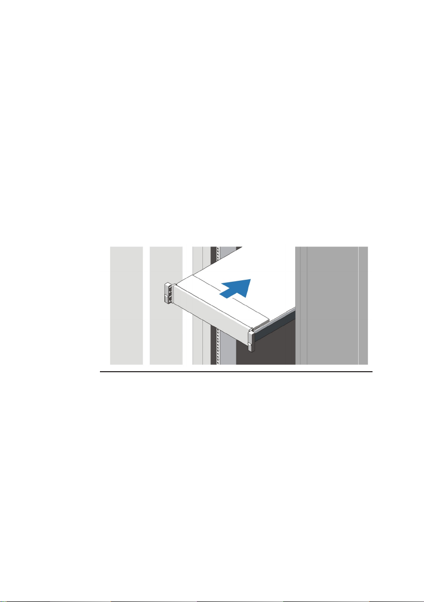
Assemble the rails and install the system in the rack following the
safety instructions and the rack installation instructions provided
with your system.
Figure 1 Installing the rails and system in a rack
6
Connecting the keyboard, mouse, and monitor
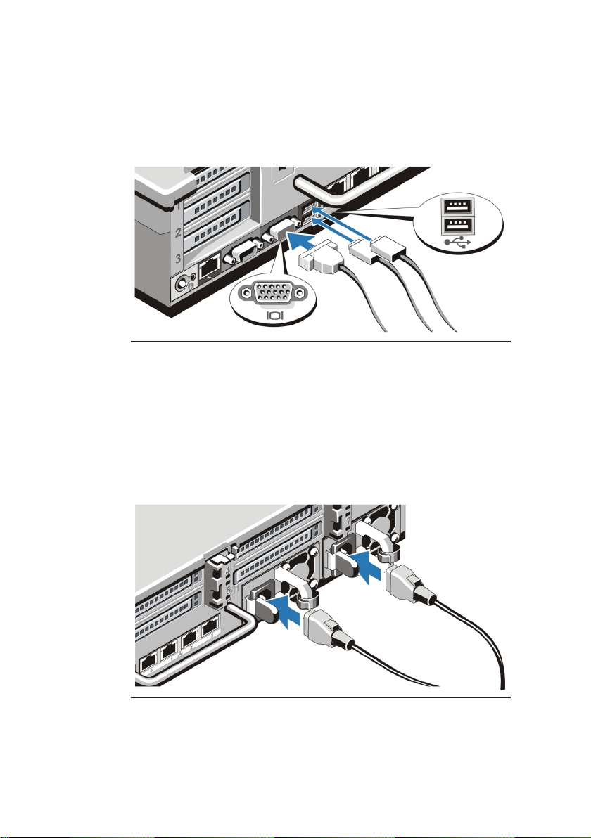
Figure 2 Connecting keyboard, mouse, and monitor
Connect the keyboard, mouse, and monitor (optional)
The connectors on the back of your system have icons indicating
which cable to plug into each connector. Be sure to tighten the
screws (if any) on the monitor's cable connector.
Connecting the power cables
Figure 3 Connecting the power cables
Connect the system's power cable to the system and, if a monitor
is used, connect the monitor's power cable to the monitor.
7
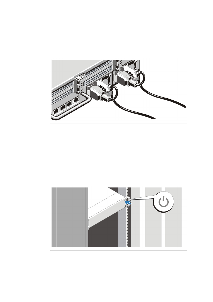
Securing the power cables
Figure 4 Securing the power cables
Bend the system power cables, as shown in the illustration, and
attach to the cable strap.
Plug the other end of the power cables into a grounded electrical
outlet or a separate power source such as an uninterruptible
power supply (UPS) or a power distribution unit (PDU).
Turning on the system
Figure 5 Turning on the system
Press the power button on the system. The power indicator should
light.
8
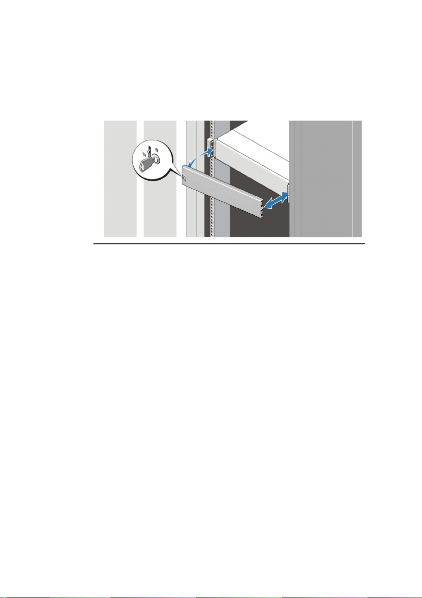
Installing the bezel
Figure 6 Installing the bezel
Install the bezel.
Connect the device to the network
The Enterprise NVR- AS 4000 G3 2U variant has two 1Gbps
Ethernet ports and two 10Gbps Ethernet ports configured as two
separate redundant pairs. A choice must be made between these
two connection options when installing the NVR-AS 4000 G3.
►If you wish to configure the unit to use link aggregation, refer to
the NVR-AS 4000 User Guide.
1Gbps Ethernet
Connect the NVR- AS to the Ethernet network using standard
CAT5 Ethernet cables.
10Gbps Ethernet
Select whether a Direct Attach twinax or 10GBASE-SR fibre optic
connection is to be used to connect to the network switch.
• Direct Attach twinax cables should be connected to an
SFP+ port on the network switch and on the back of the
NVR-AS 4000.

9
• Fibre optic connection requires 10GBASE-SR SFP+ fibre
optic transceivers to be installed in the NVR-AS 4000 SFP+
port and on the network switch before attaching a short
range fibre optic patch cable.
10Gbps Ethernet connections are not supplied with the NVR-AS
4000 and must be purchased separately.
SFP+ Fibre optic transceiver modules for the Enterprise NVR-AS
4000 G3 must be purchased from IndigoVision to ensure
compatibility. The corresponding network switch SFP+ fibre optic
module purchase and compatibility is the responsibility of the user.
Complete the initial system setup
When you power up the Enterprise NVR-AS4000 G3 for the first
time, the unit goes through self test. During this stage the device
performs initial configuration. When the self test is complete, the
unit reboots.
Before you can configure the rest of the Enterprise NVR-AS 4000
settings, the Administrator password must be set. To do this,
access the web interface on the device. The first time you do so,
you will be prompted to set the Administrator password.
When first powered on, the Enterprise NVR-AS 4000 is set to use
DHCP. To get the IP address of the system, which is required to
access the web interface, you can do one of the following:
• Query your DHCP server to find which IP address has been
assigned to the system
• Configure the system to use a static IP address
►For more information on how to do this, see "Using a
monitor and keyboard" on page 11

10
Until the Administrator password is set, you will not be able to
discover the Enterprise NVR-AS 4000 in Control Center or perform
any further configuration.
When first powered on, the Enterprise NVR- AS 4000 G3 RAID
arrays commence a background initialization process. During this
operation the RAID array is fully operational but does not have full
redundancy until it completes.

Configuration
You can configure the Enterprise NVR-AS 4000 G3 using the Web
Configuration pages, or a monitor and keyboard.
DHCP
If your network supports DHCP connections, attach the device to
the network and a valid IP address is automatically assigned. The
Enterprise NVR-AS 4000 G3 can then be discovered using the
Control Center front-end application.
If your network does not support DHCP, the device will not be
assigned an IP address and you must follow the monitor and
keyboard instructions.
The Enterprise NVR-AS 4000 G3 2U/G3 2U variant only supports
either the 1Gbps ethernet pair or the 10Gbps ethernet pair to be
connected at any given time, not both.
Using a monitor and keyboard
1. Connect the keyboard and monitor to the device and press
Enter.
You should see the following prompt:
login:
2. Log in to the device using the username config and
password config.
The device prompts you to enter the new configuration
values.
3. At each prompt, press Enter to accept the current value.
•DHCP - Enter Yor Nto chose between a DHCP or static
IP configuration.
•IP Address — Enter the IP address for the unit's
network connection.

12
•Subnet Mask — Enter the IP network subnet mask for
the unit's network connection.
•Gateway — Appropriate default gateway for remote
network access: this is only required if the unit is to
communicate with devices on a different subnet.
•Preferred/Alternate Name Server Address — Enter
the IP address of the DNS server used to convert
network names into numerical IP addresses. You only
need to enter a name servers if you wish to specify NTP
or SMTP server addresses as names and not as IP
addresses.
•NVR name — Enter a name to describe the unit.
•NVR location — Enter a name to describe the location
of the unit.
•Reset network security — Enter Yto reset all
passwords used to access device, disable IP Access
Restrictions, and reset the device to HTTP use only by
deleting any HTTPS certificate or certificate request.
You are now ready to attach the device to the network.
Web Configuration pages
To access the Web Configuration pages, enter the IP address of
your device into a web browser.
If a web access password has not been previously defined for the
device you will be prompted to set a password.
The password must contain between 8 and 32 printable ASCII (7-
bit US-ASCII) characters. Enter the password again to confirm it.
The login page is then displayed. Use the web access password
to log in, and the Home page is displayed.
The web access password must be configured before the NVR is
capable of performing any authenticated network services,
including recording.

Technical specification - Enterprise NVR-
AS 4000 G3 2U
Power
AC Power Supply (per power supply)
Wattage 750 W
Heat dissipation
Heat dissipation is calculated using the power
supply wattage rating.
2891 BTU/hr maximum (750
W power supply)
Voltage
This system is also designed to be connected
to IT power systems with a phase to phase
voltage not exceeding 230 V.
100/240 V AC, autoranging,
50/60 Hz
Battery
Coin-cell battery 3 V CR2032 Lithium coin cell
Physical
Height 87.3 mm (3.44 inch)
Width
With rack latches 482.4 mm (18.98 inch)
Without rack latches 444 mm (17.08 inch)
Depth (excludes bezel) 755.8 mm (29.75 inch)
Weight (maximum) 33.1 kg (72.97 lb)

14
Environmental
Temperature
Operating
10 °C to 35 °C (50 °F to 90 °F) with no direct sunlight on the
equipment.
Maximum temperature gradient of 20°C/h (68°F/h).
Storage -40 °C to 65 °C (-40 °F to 149 °F)
Maximum temperature gradient of 20°C/h (68°F/h).
Relative Humidity
Operating 10% to 80% (noncondensing) at a maximum wet bulb
temperature of 29 °C (84.2 °F)
Storage 5% to 95% at a maximum wet bulb temperature of 33 °C (91 °F)
Maximum Vibration
Operating 0.26 Grms at 5-350 Hz (all operation orientations)
Storage 1.88 Grms at 10-500 Hz for 15 min (all six sides tested)
Maximum Shock
Operating Six consecutively executed shock pulses in the positive and
negative x, y and z axes of 6 G for up to 11 ms
Storage
Six consecutively executed shock pulses in the positive and
negative x, y, and z axes (one pulse on each side of the system)
of 71 G for up to 2 ms
Altitude
Operating 3048 m (10,000 ft)
Operating temperature de-rating:
Up to 35 °C
(95 °F):
Maximum temperature is reduced by 1°C/300 m (1°F/547 ft)
above 950 m (3,117 ft).
35 °C to 40 °C
(95 °F to 104
°F):
Maximum temperature is reduced by 1°C/175 m (1°F/319 ft)
above 950 m (3,117 ft).
40 °C to 45 °C Maximum temperature is reduced by 1°C/125 m (1°F/228 ft)

15
(104 °F to 113
°F):
above 950 m (3,117 ft).
Storage 12,000 m (39,370 ft)
Airborne Contaminant Level
Class G1 as defined by ISA-S71.04-1985

Further information
For further information, please refer to the Enterprise NVR- AS
4000 G3 Linux User Guide available at:
https://partners.indigovision.com.

17

18

19

This manual suits for next models
1
Table of contents
Other IndigoVision Network Hardware manuals


Popular Network Hardware manuals by other brands

Sanyo
Sanyo PJ-Net Organizer POA-PN30 owner's manual

Siemens
Siemens SINUMERIK 840Di sl Function manual

Cabletron Systems
Cabletron Systems SmartSwitch 6000 Management guide

Black Box
Black Box MX325A-HS Specifications

AirLive
AirLive WHB-1100 user manual

Hamilton/Buhl
Hamilton/Buhl SNIPS SNIP18 instruction manual


