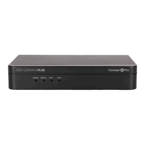
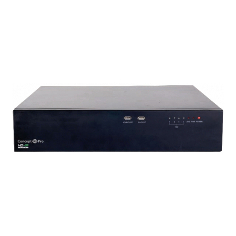
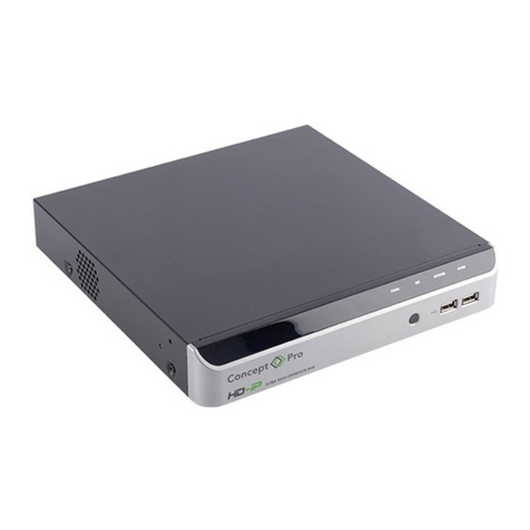
Concept Pro VHDIPL-V3 Series User manual

VHDIPL-V3 User Manual - October 2017
VHDIPL-V3 Series
USER MANUAL
NETWORK VIDEO RECORDER

VHDIPL-V3 User Manual - October 2017
Purpose
This document describes the hardware installation, basic operation, network access, network confi guration, routine maintenance, fault analysis, and troubleshooting
of the Network Video Recorder (NVR).
Intended Audience
This document is intended for:
• Technical support engineers
• Maintenance engineers
WARNING Alerts you to monitor danger, which if not avoided, may cause minor or moderate injuries.
CAUTION Alerts you to risks. Neglecting these risks may cause device damage, data loss, device performance
deterioration, or unpredictable results.
NOTE Provides noteworthy information.
Important Statement
Users are required to enable and maintain the lawful interception interfaces of video surveillance products in strict compliance with relevant laws and regulations.
Installation of surveillance devices in an offi ce area by an enterprise or individual to monitor employee behaviour and working effi ciency outside the permitted scope
of the local law and the use of video surveillance devices for eavesdropping or other illegal purposes constitute behaviours of unlawful interception.
WARNING
Please strictly observe and adhere to installation requirements when installing the device; The manufacturer will not be held responsible for device damage caused
by users’ non-compliance with these requirements.
Please strictly conform to local electrical safety standards and use power adapters that are marked with the local standard when installing and using this device.
Please use the accessories delivered with this device, voltage must meet input voltage requirements for this device.
If this device is installed in places with inconsistent voltage or where lightning storms frequently occur, ensure the device is grounded to discharge any high energy
such as electrical surges, which will help prevent damage.
When this device is in use, ensure that no water or other liquids enter the device. If liquid unexpectedly enters the device, immediately turn off the power and
disconnect all cables (such as power cables, video cables and network cables) from the device.
CAUTION
Handle with care to prevent damage during transportation and storage. The warranty does not cover any device damage that is caused during transportation after
the original packaging is removed.
Ensure the device is not subject to falls or direct strikes
Keep the device away from electromagnetic interference, and do not install the device in places with unstable surfaces. Doing so may cause connected cables to
become loose and cause the device to malfunction.
Clean the device with a soft, dry cloth. For stubborn dirt, use a neutral cleanser to dampen the cloth then gently wipe the dirt away and dry the area.
Do not block the ventilation to the NVR; this is required to cool the NVR. Follow the installation instructions provided in this document when installing the device.
Do not install near heat sources such as radiators, electric space heaters, or other heat-producing equipment.
Do not install device near moist, dusty, extremely hot or cold environments or places that are subject to radiation.
If the device is installed outdoors, take measures to ensure insects and moisture cannot enter the device to avoid circuit board corrosion, which in turn will have a
negative affect monitoring.
If the NVR is idle for an extended period of time, remove the power plug.
Special Announcement
All complete products sold by the manufacturer are delivered along with nameplates, quick setup guides, and accessories after strict inspection. The manufacturer
will not be held responsible for counterfeit products.
The manufacturer may update this manual according to product feature enhancements or changes at regular intervals to update the software and hardware
described in this manual without prior notice, the updated information will be added in later versions of the manual.
NOTE
For more information, please refer product web pages.

VHDIPL-V3 User Manual - October 2017
2 Device Structure
Device Ports
NOTE
Different devices may have different ports and cable connections. The following information is accurate at time of writing.
Front panel description of device refers to table 2-1.
Table 2-1 Front panel description
Rear panel description of device, please refer to table 2-2.
Port Name Description
PWR Indicator When the NVR is operational, the PWR indicator is steady on.
HDD Indicator Hard disk status indicator, LED fl ashes on data transmission.
USB Supports connection to a USB mouse, keyboard, 2x USB fl ash drive for backup and mouse.
POE POE Port Number LED is active when POE IP camera is connected (NVR models with PoE only).
Port Name Description
Alarm input and alarm output/RS485.
LINE OUT/ LINE IN Audio output and audio input.
RESET Factory reset button.
POE POE Network Interface.
GLAN 1, GLAN 2, LAN RJ45 10 /100/1000 Mbps adaptive Ethernet port.
VGA Video output connectors.
HDMI, HDMI2
RS232 Standard RS232 serial communication interface of the device (VHDIPL-32V3 only).
USB 3.0 USB port for faster data transfer.
e-SATA External hard disk connection.
Grounding screw.
Power switch.
AC 110V/220V power input.
DC 48V DC 48V Power supply input (VHDIPL-4V3 only).
Packing list – VHDIPL-32V3 QTY
Quick Setup Guide 1
CD-ROM 1
Mouse 1
4-pin Terminal Block 8
AC Power Cord 1
Rack Mount Ears 2
Packing List – VHDIPL-8V3,
16V3
QTY
Quick Setup Guide 1
CD-ROM 1
Mouse 1
4-pin Terminal Block 2
AC Power Cord 1
Rack Mount Ears 2
Packing List - VHDIPL-4V3 QTY
Quick Setup Guide 1
CD-ROM 1
Mouse 1
Terminal Block 2
AC Power Cord 1
DC 48V 1A Power Supply 1
Rack Mount Ears 2
1 Contents of NVR box

VHDIPL-V3 User Manual - October 2017
372mm
306mm
44.5mm
440mm
440mm 482.6mm
434.8mm
89.8mm
67mm
369mm
VHDIPL-4V3
VHDIPL-8V3
VHDIPL-16V3
VHDIPL-32V3
2.1 Device Dimensions
Figure 2-1 Dimensions (Unit: mm)

VHDIPL-V3 User Manual - October 2017
3.1 Startup
Ensure the NVR is securely connected at the power source and the monitor is connected via the HDMI or VGA video output before starting NVR. In some cases, the
NVR will automatically power on when connected to a power supply.
CAUTION Ensure the power supply meets local regulations as in some environments, if the power supply fl uctuates the NVR may not work properly or
could become permanently damaged
During the power up process, the power LED indicator on the front panel will be steady, and the NVR will self-check and display on-screen test and results. Please
pay attention to this. The startup process takes approximately 2 minutes; if a hardware abnormality is detected during the NVR self-check, will be present next to
the test. Select continue or shutdown in the bottom right corner of the screen, continue will redirect you to the NVR login screen.
NOTE
Hard disk detection is performed during start up. If the detection fails, possible causes include:
The hard disk is new and unformatted. In this case, format the hard disk based in “Quick Setup”.
The hard disk is formatted, but the fi le system is inconsistent with the one supported by the NVR.
The hard disk is damaged.
Figure 3-1 Login
3.2 Adding IP Network Cameras
By PoE
After the PoE network interfaces are connected to IP cameras, the NVR will automatically add the IP cameras. Figure 3-3 shows the network topology of the NVR.
NOTE
The default user name is admin.
The default password is admin.
It is advised that you change the password when you log in the system
for fi rst time to ensure system security, the VHDIP-V3 Range of NVR’s
now support enhanced security passwords, allowing for the use of
complex passwords. For new users, this must be used.
Once the user name and password are entered the NVR UI will be
displayed.
CAUTION
could become permanently damaged
During the power up process, the power LED indicator on the front panel will be steady, and the NVR will self-check and display on-screen test and results. Please
pay attention to this. The startup process takes approximately 2 minutes; if a hardware abnormality is detected during the NVR self-check, will be present next to
Figure 3-2 Network topology of the POE NVR, applies to the
VHDIPL-4V3, VHDIPL-8V3, VHDIPL-16V3
By Network Search
Connecting IP cameras from the network is possible only when the NVR and cameras are within the same IP address range. This type of network confi guration
includes other types of network devices, in addition to the IP cameras and NVR. When the IP cameras and NVR are confi gured in a way that enables them to
communicate with ease over the network, there should be no issues. In this topology, the user must use the network search function from the Quick Setup page to
search and add IP cameras. The NVR will not automatically populate IP cameras from a network.
For details, see chapter 4.1 “Quick Setup”.

VHDIPL-V3 User Manual - October 2017
4. Quick Confi guration
The NVR is embedded with a web server and supports common browsers such as Internet Explorer, Chrome, Firefox, and Safari. Operations such as quick setup,
real-time preview, video playback, alarm search, NVR setup, and camera setup can be performed through the web browser. To open the web browser UI, enter the
IP address found on the Quick Setup page (default: 192.168.0.121) in the URL fi eld and press Enter. The login page is displayed as shown in fi gure 3-1.
4.1 Quick Setup
To quickly access some of the NVR’s major features from the network, navigate to the Quick Setup tab. From here the NVR confi gurations such as; network
confi guration, disk management, time setting, IP camera search, video confi guration, camera network confi guration, stream confi guration, and mobile detection
confi guration can be set up, as shown in Figure 4-1
Figure 4-1 Quick Setup Tab
4.1.1 NVR Setup
Section 1: NVR Information: Set the device name and device time of the NVR.
Sync Camera Time with the NVR: Manually set time or automatically by confi guring an NTP server connection.
If the manual mode is selected, click to synchronize the time of the connected IP cameras. If the auto mode is selected, the NVR will automatically synchronize the
time of connected IP cameras.
Section 2: NVR network confi guration: this section allows the user to managed the NVR local and wide area networks. Confi gure the NVR to automatically get the
IP address (DHCP) and set the IP address, subnet mask, default gateway, DNS address of the NVR; Display the network connection status and speed.
Section 3: Hard disk management: Manage the internal storage of the NVR; Format the hard disk drive(s); View the status of the hard disk (usable, abnormal,
unformatted, and unavailable); Check the used space and total space of the hard drive.
CAUTION
Formatting the HDD’s will clear all video data; only use this function when necessary.
Ensure to select unload on the HDD before removing it from the NVR; otherwise, the hard disk may become corrupt or data could be lost. Remove power to the NVR
before removing hard drives.
The NVR must be connected to a stable power supply; a fl uctuating power supply may cause damaged or corrupt data.
Section 4 - Camera setup
IP camera setup
From the camera setup window users can view the status of connected IP cameras and apply a name, confi gure the IP address, set the record schedule, stream
settings, and motion alarm settings if supported by the IP camera.
• Viewing the status of an IP camera; Online, Offl ine or Incorrect account – the NVR will prompt for the username and password to be entered.
• Change the channel name: Click a selected channel name then enter the desired name for the channel in the text fi eld.
• Set a record schedule: Click the record status to open the Record Policy window. From here the NVR can be confi gured to set a recording schedule for the
week and can enable audio recording as well as hard drive operation once full.
• Set a stream: Click the stream status to open the stream setting of that channel; Set stream parameters – resolution, bit rate and quality for stream 1 & 2.
• Set a motion alarm: Click the tool icon to open the motion alarm confi guration window. Enable the motion alarm and when it is active along with any actions the
NVR should do when it receives a motion alarm; such as record, send email or alarm output.
Section 5 - Camera search and deletion
To add cameras to the NVR from the network, the IP camera search tool must be used: click Search Camera, then click Scan. The NVR will scan the network for
compatible IP cameras.
Click to go to the camera searched page, use the tick boxes to select the cameras by IP address to add to cameras managed by the NVR. Then click Ok.
The NVR will show how many cameras are managed and how many are supported. To remove cameras from this page use the opposite arrow key once the camera
is selected .
To remove managed cameras, check the cameras in the camera list then click to Delete Camera.
Click to go to the camera searched page, use the tick boxes to select the cameras by IP address to add to cameras managed by the NVR. Then click Ok.
1
4
5
3
2

VHDIPL-V3 User Manual - October 2017
4. 2 Live video
To view a real-time video, click the Live Video tab and select the cameras from the camera list panel on the right hand side, shown in fi gure 4-2. Any custom layouts
saved in the NVR can be used to load a view in the web browser and view alarm information received.
Figure 4-2 Web UI -Live Video
5 Mobile Phone Client
• Download Concept Pro Lite 3 for iOS and Android.
• Click to open the main menu of the smart phone app. As displayed in fi gure 5-1. The following
operations are supported within the app:
• Live preview – view up to 16 channels, open landscape camera view, swipe the channel view to change
camera, take a channel snapshot and video which is saved to the smart phone memory, PTZ cameras, turn
on the alarm output of the NVR remotely.
• Playback – View playback video recorded by the VHDIPL-V3.
• Devices – Add, Edit and remove connections to Concept Pro Lite NVR’s. Add devices from IP address or
P2P ID using QR scan feature.
• Favourite – View a list of favourite cameras for quick access.
• Image – Explorer of photo and videos saved from live view.
• Alarm – View alarm information from connected NVR’s.
Figure 5-1 Concept Pro Lite 3 - Main menu
Download Concept Pro Lite 3 for iOS and Android.
Click to open the main menu of the smart phone app. As displayed in fi gure 5-1. The following

VHDIPL-V3 User Manual - October 2017
This manual suits for next models
4
Table of contents
Other Concept Pro Network Hardware manuals
Popular Network Hardware manuals by other brands

Datacom Systems
Datacom Systems WANswitch W2358DSL Hardware guide

Tektronix
Tektronix TD140 Hardware maintenance guide

Fortinet
Fortinet FortiMail-5001A quick start guide

Salusfin
Salusfin SF-930EU User's installation guide

Hypertec
Hypertec CIARA ORION HF X410R-G6 user manual

ADTRAN
ADTRAN T1 Nx64 HTU-R Installation and Maintenance