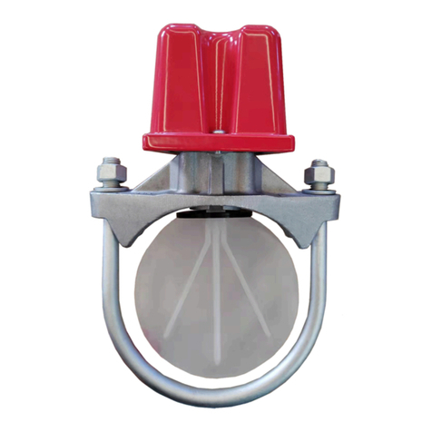
Tyco TOSY-1 User manual

Model TOSY Outside Screw and Yoke Valve
Supervisory Switch, APACOnly
NATIONAL FIRE PROTECTION ASSOCIATION and NFPA are registered trademarks of National
Fire Protection Association
Important: Refer to technical data sheet TFP2300
for warnings pertaining to regulatory and health
information.
Scan the QR code or enter the URL in a web
browser to access the most up-to-date electronic
version of this document. Data rates may apply.
docs.jci.com/tycofire/screw-and-
yoke-valve-supervisory-switch
NOTICE
The TYCO Model TOSY Outside Screw and Yoke
Valve Supervisory Switch described herein must
be installed and maintained in compliance with this
document, in addition to the standards of any other
authorities having jurisdiction. Failure to do so may
impair the performance of the related devices.
The owner is responsible for maintaining their fire
protection system and devices in proper operating
condition. Contact the installing contractor or product
manufacturer with any questions.
General description
The TYCO Model TOSY Outside Screw and Yoke Valve
Supervisory Switch is designed to monitor the position of
an outside screw and yoke type gate valve, and indicate
when the valve is not in the open position.
The switch is weather proof and tamper resistant. The
cover incorporates tamper resistant screws that require
a special tamper resistant key for removal. One tamper
resistant key is supplied with each device.
The switch mounts to most TYCO outside screw and yoke
gate valves in a size range of 2 in. (50 mm) to 24 in. (600
mm).
Models
The switch models are based on the number of sets of
single-pole, double-throw (SPDT) contacts featured as
described in Table 1.
Table 1: Switch models
Model Description
TOSY-1 1 set of SPDT contacts
TOSY-2 2 sets of SPDT contacts
TFP2113
MAY 2022

Assembly
Figure 1: Main components and dimensions
Callout Description
1 Cover
2 Gasket
3 Housing
4 Tamper resistant cover screw
5 Trip rod locking screw
6 Trip rod
7 Bracket
8 Carriage bolt
9 Hex nut
10 Bracket lock screw
11 Clamp bar
Callout Dimension
A 4.55 in. (116 mm)
B 2.36 in. (60 mm)
C 4.84 in. (123 mm)
D Minimum: 1.77 in. (45 mm); Maximum: 3.35
in. (85 mm)
E 1.65 in. (42 mm)
F 6.18 in. (157 mm)
Figure 2: Hook components
Callout Description
9 Hex Nut
12 J hook
Technical Data
Approvals
• UL and cUL Listed
• FM Approved
• CE
Contact ratings
• 10 A at 125/250 VAC
• 2.5 A at 30 VDC Resistive
Operating temperature range
• -40°F to +140°F (-40°C to +60°C)
IP rating
• IP67
Note: The switch is suitable for indoor or outdoor
use.
Dimensions
• See Assembly section.
Physical characteristics
Cover Die-cast finish, powder coat
Base Die-cast finish
Note: All components have corrosion resistant
finishes.
Model TOSY Outside Screw and Yoke Valve Supervisory Switch, APAC Only2

Operation
The TYCO Model TOSY Outside Screw and Yoke Valve
Supervisory Switch is mounted with carriage bolts and a
bracket. The normal condition is the valve is fully open,
and the supervisory switch trip rod is in the groove of the
valve stem.
Closing the valve causes the trip rod to ride up out of the
groove and activates the switch. Removing the switch
from the valve causes the spring to pull the trip rod in the
other direction which also activates the switch.
Installation
The TYCO Model TOSY Outside Screw and Yoke Valve
Supervisory Switch must be installed according to the
instructions in this section.
Installing the ½ inch to 2 ½ inch size
range
Before you begin:
• The ½ in. to 2 ½ in. size switch range must be installed
according to the instructions in this section.
1. Choose an installation location with adequate
clearance for installing or removing the switch.
2. Position the indicator valve to the FULL OPEN
position.
3. Locate the switch with the bracket near the hand
wheel as shown in Figure 3. Avoid creating a pinch
point between the wheel and the switch.
4. Loosen the locking screw that holds the trip rod
in place. Adjust the rod length to extend past the
valve screw but does not contact the bracket clamp
bar.
Note: If the trip rod length is too long,
loosen the locking screw and remove the
trip rod from the trip lever. Break off the
1 in. (2.54 mm) excess length at the notch
using pliers. Re-install the trip rod and repeat
step 4.
5. Tighten the locking screw to 5 in-lbs (0.56 N·m)
minimum to secure the trip rod in place, and seal
the enclosure.
6. Mount the switch and finger-tighten the carriage
bolts on the clamp bar assembly.
Note: Do not tighten the assembly in place at
this time.
Note: J-hooks are supplied to replace the
carriage bolt and clamp bar for valves with
limited clearance.
7. Deburr and smooth the edges of the groove, to
allow the trip rod to slide in and out of the groove
without catching as the valve opens and closes, and
to prevent damage to the valve packing.
8. To make final adjustments, loosen the two screws
on the bracket a small amount, and use the micro-
adjustment feature as shown in Figure 3. Final
adjustments are complete when with the valve in
the open position, there is no continuity between
COM and NO terminals, and the plungers are
depressed by the actuator.
Figure 3: ½ in. to 2 ½ in. size range installation
Callout Description
3 Housing
7 Bracket
10 Bracket lock screw
9. Tighten the adjustment screws and all the
mounting hardware to 20 in-lbs (2.26 N·m)
minimum. Verify the rod slides in and out of the
groove easily.
10. Verify the switch activates within two turns when
the valve is operated from the FULL OPEN position
toward the CLOSED position.
11. Reinstall the cover and tighten the tamper resistant
cover screws to a minimum 15 in-lbs (1.69 N·m) to
form a proper seal.
Model TOSY Outside Screw and Yoke Valve Supervisory Switch, APAC Only 3

Installing the 3 inch to 12 inch size range
Before you begin:
• The 3 in. to 12 in. switch size range must be installed
according to the instructions in this section.
1. Ensure the valve is in the FULL OPEN position.
Locate the switch across the valve yoke as far
from the valve gland as possible so that the spring
loaded trip rod of the switch is pulled against the
non-threaded portion of the valve stem. Position
the switch with the bracket near the hand wheel.
Avoid creating a pinch point between the wheel
and the switch.
2. Mount the switch loosely using the carriage bolts
and clamp bar provided.
3. Loosen the locking screw that holds the trip rod
in place. Adjust the rod length to extend past the
valve screw but does not contact the bracket clamp
bar.
Note: If the trip rod length is too long,
loosen the locking screw and remove the
trip rod from the trip lever. Break off the
1 in. (2.54 mm) excess length at the notch
using pliers. Re-install the trip rod and repeat
step 4.
4. Tighten the locking screw to 5 in-lbs (0.56 N·m)
minimum to secure the trip rod in place and seal
the enclosure.
5. Mount the switch and finger-tighten the carriage
bolts on the clamp bar assembly.
Note: Do not tighten the assembly in place at
this time.
Note: J-hooks are supplied to replace the
carriage bolt and clamp bar for valves with
limited clearance.
6. Deburr and smooth the edges of the groove, to
allow the trip rod to slide in and out of the groove
without catching as the valve opens and closes, and
to prevent damage to the valve packing.
Note: On valves with limited clearance use
the j-hooks supplied instead of the carriage
bolts and clamp bar to mount the valve.
7. To make final adjustments, loosen the two screws
on the bracket a small amount and use the micro-
adjustment feature as shown in Figure 4. Final
adjustments are complete when with the valve in
the open position, there is no continuity between
COM and NO terminals, and the plungers are
depressed by the actuator.
Figure 4: 3 in. to 12 in. size range installation
Callout Description
3 Housing
7 Bracket
10 Bracket lock screw
8. Tighten the adjustment screws and all mounting
hardware securely to 20 in-lbs (2.26 N·m) minimum.
Check to ensure that the rod moves out of the
groove easily and that the switch activates within
two turns when the valve is operated from the FULL
OPEN to the CLOSED position.
9. Verify the switch activates within two turns when
the valve is operated from the FULL OPEN position
toward the CLOSED position.
10. Reinstall the cover and tighten the tamper resistant
cover screws to a minimum 15 in-lbs (1.69 N·m) to
form a proper seal.
Model TOSY Outside Screw and Yoke Valve Supervisory Switch, APAC Only4

Wiring the switch
Before you begin:
• The switch must be wired according to the instructions
in this section.
1. Remove the tamper resistant screw with a key.
Note: Do not leave the cover off for an
extended period of time.
2. Route the wiring through an agency approved
conduit connector and attach the connector to the
switch.
3. Connect the wiring to the appropriate terminals
according to the intended use as shown in Figure 5.
Figure 5: Typical wiring connections
Care and maintenance
The TYCO Model TOSY Outside Screw and Yoke Valve
Supervisory Switch must be maintained and serviced in
accordance with this section, in addition to any specific
requirements of the NFPA, and any impairment must be
immediately corrected. The inspection procedure must be
performed as described.
Before closing a fire protection system control valve for
inspection or maintenance work on the fire protection
system that it controls, permission to shut down the
affected fire protection system must first be obtained
from the proper authorities and all personnel who may
be affected by this action must be notified. After placing
a fire protection system in service, notify the proper
authorities and advise those responsible for monitoring
proprietary and/or central station alarms.
The owner is responsible for the inspection, testing,
and maintenance of their fire protection system and
devices in compliance with this document, as well as
with the applicable standards of the NATIONAL FIRE
PROTECTION ASSOCIATION such as NFPA 25, in addition
to the standards of any authority having jurisdiction (AHJ).
Contact the in stalling contractor or product manufacturer
with any questions.
It is recommended that automatic sprinkler systems
be inspected, tested, and maintained by a qualified
inspection service.
Inspecting the supervisory switch
Before you begin:
• The inspection procedure must be performed as
specified, in addition to any specific requirements of
the NFPA, and any impairment must be immediately
corrected.
• The operation of the switch and its associated
monitoring system must be tested upon completion of
installation.
• Test the switch periodically in accordance with
applicable NFPA codes and standards and/or the
authority having jurisdiction (AHJ). A quarterly
arrangement is recommended.
To inspect the supervisory switch, complete the following
steps:
1. Turn the valve operating mechanism towards the
the closed position. Verify the switch operates
within the first two revolutions of the operating
mechanism.
2. Fully close the valve and verify the switch does not
reset.
3. Fully open the valve and verify the switch restores
to the normal condition.
Model TOSY Outside Screw and Yoke Valve Supervisory Switch, APAC Only 5

Limited Warranty
For warranty terms and conditions, visit http://www.tyco-
fire.com.
Ordering Procedure
Contact your local distributor for availability. When
placing an order, indicate the full product name, and part
number (PN).
Outside screw and yoke valve
supervisory switch
Specify: Model (see Table 2), Outside screw and yoke valve
supervisory switch, quantity, PN (see Table 2).
Table 2: Switch part numbers
Model Part number
TOSY-1 300201
TOSY-2 300202
© 2022 Johnson Controls. All rights reserved. All specifications and other information shown were current as of document revision and
are subject to change without notice.
www.johnsoncontrols.com
This manual suits for next models
3
Table of contents
Other Tyco Switch manuals
Popular Switch manuals by other brands

Panasonic
Panasonic WJFS216 - SWITCHER operating instructions

Black Box
Black Box ServSwitch Octopus KV1701E user manual

3One data
3One data IES3016 Series user manual

3One data
3One data IES2305 Series Quick installation guide

BZB Gear
BZB Gear BZ-MVS4X4-4K user manual

New Star
New Star NS-211Micro-USB user manual