Tyler Refrigeration N7DNL Supplement

Installation & Service
Manual
N7DNL, NHD(L/M)
This manual has been designed to be used in conjunction with the
General (UL/NSF) Installation & Service Manual.
Save the Instructions in Both Manuals for Future Reference!!
This merchandiser conforms to the American National Standard Institute & NSF International Health and Sanitation standard ANSI/NSF 7 - 2003.
PRINTED IN Specifications subject to REPLACES ISSUE PART
IN U.S.A. change without notice. EDITION DATE 6/07 NO. 9055758 REV. —
Tyler Refrigeration * Niles, Michigan 49120
EXTENDED HEIGHT MULTI-SHELF DAIRY/DELI/PRODUCE/JUICE
MERCHANDISERS
Medium Temperature Self Serve Display Cases

CONTENTS
N7DNL, NHD
Page 2 June, 2007
Page
Specifications
N7DNL Specification Sheets . . . . . . . . . . . . . . . . . . . . . . . . . . . . . . . 4
NHDL/NHDM Specification Sheets . . . . . . . . . . . . . . . . . . . . . . . . . . 6
Pre-installation Responsibilities . . . . . (See General-UL/NSF I&S Manual)
Installation Procedures
Carpentry Procedures . . . . . . . . . . . . . . . . . . . . . . . . . . . . . . . . . . . 8
Case Pull-Up Locations . . . . . . . . . . . . . . . . . . . . . . . . . . . . . . . . . . 8
Joining Rear Load Cases to Coolers . . . . . . . . . . . . . . . . . . . . . . . . . 8
Electrical Procedures . . . . . . . . . . . . . . . . . . . . . . . . . . . . . . . . . . . . 8
Plumbing Procedures . . . . . . . . (See General-UL/NSF I&S Manual)
Refrigeration Procedures . . . . . (See General-UL/NSF I&S Manual)
Defrost Information . . . . . . . . . . . . . . . . . . . . . . . . . . . . . . . . . . . . . 8
Defrost Control Charts . . . . . . . . . . . . . . . . . . . . . . . . . . . . . . . . . . . 8
Installation Procedure Check Lists (See Gen.-UL/NSF I&S Manual)
Wiring Diagrams . . . . . . . . . . . . . . . . . . . . . . . . . . . . . . . . . . . . . . . . . . . . 9
N7DNL Domestic & Export (50 Hz) Case Circuits (8’ Cases) . . . . . . 9
N7DNL Domestic & Export (50 Hz) Case Circuits (12’ Cases) . . . . 10
NHD(L/M) Dom. & Export (50 Hz) Case Circuits (6’ & 8’ Cases) . . 11
NHD(L/M) Dom. & Export (50 Hz) Case Circuits (12’ Cases) . . . . . 13
Cleaning and Sanitation . . . . . . . . . . . (See General-UL/NSF I&S Manual)
Component Removal and Installation Instructions for Cleaning 15
Shelves and Shelf Brackets . . . . . . . . . . . . . . . . . . . . . . . . . . . . . . 15
Bottom Trays . . . . . . . . . . . . . . . . . . . . . . . . . . . . . . . . . . . . . . . . . . 15
Front Air Ducts . . . . . . . . . . . . . . . . . . . . . . . . . . . . . . . . . . . . . . . . 15
Rear Duct Panels . . . . . . . . . . . . . . . . . . . . . . . . . . . . . . . . . . . . . . 15
Discharge Air Honeycomb . . . . . . . . . . . . . . . . . . . . . . . . . . . . . . . 15
Top Duct . . . . . . . . . . . . . . . . . . . . . . . . . . . . . . . . . . . . . . . . . . . . . 15
Front Cladding . . . . . . . . . . . . . . . . . . . . . . . . . . . . . . . . . . . . . . . . 16
Cleaning Instructions . . . . . . . . . . . . . . . . . . . . . . . . . . . . . . . . . . . 16
Stainless Steel Cleaning Methods . . . . . . . . . . . . . . . . . . . . . . . . 16

Page
General Information . . . . . . . . . . . . . . . . . . . . . . . . . . . . . . . . . . . . . . . . 18
NSF Product Thermometer Installation . . . . . . . . . . . . . . . . . . . . . 18
Egg Merchandiser Kit . . . . . . . . . . . . . . . . . . . . . . . . . . . . . . . . . . . 18
Peg Bar Information . . . . . . . . . . . . . . . . . . . . . . . . . . . . . . . . . . . . 19
Peg Bar Information for Cannon Magna Bar Peg Display Systems 20
Service Instructions . . . . . . . . . . . . . . . . . . . . . . . . . . . . . . . . . . . . . . . . 21
Preventive Maintenance . . . . . . . (See General-UL/NSF I&S Manual)
Ballast and Lighting Locations . . . . . . . . . . . . . . . . . . . . . . . . . . . . . 21
Defrost Heater Replacement . . . . . . . . . . . . . . . . . . . . . . . . . . . . . . 22
Parts Information . . . . . . . . . . . . . . . . . . . . . . . . . . . . . . . . . . . . . . . . 23
Operational Parts Lists . . . . . . . . . . . . . . . . . . . . . . . . . . . . . . . . . . . 23
Cladding and Trim Parts List . . . . . . . . . . . . . . . . . . . . . . . . . . . . . . 24
TYLER Warranty . . . . . . . . . . . . . . . . . (See General-UL/NSF I&S Manual)
The following Extended Height Medium Temperature, Multi-Shelf Dairy, Deli, Produce and
Juice Merchandiser models are covered in this manual:
MODEL DESCRIPTION
N7DNL 8’ & 12’ EXTENDED HEIGHT MED. TEMP. NARROW MERCHANDISER
WITH 18” FRONT
NHDL 6’, 8’ & 12’ EXTENDED HEIGHT MED. TEMP. MERCHANDISER
WITH 18” FRONT
NHDM 6’, 8’ & 12’ EXTENDED HEIGHT MED. TEMP. MERCHANDISER
WITH 22” FRONT
Installation & Service Manual N7DNL, NHD
June, 2007 Page 3

Page 4 April, 2008
SPECIFICATIONS
N7DNL Extended Height Narrow Multi-Shelf Medium Temp Merchandisers

April, 2008 Page 5

Page 6 April, 2008
NHD(L, M) Extended Height Multi-Shelf Medium Temp Merchandisers

April, 2008 Page 7

N7DNL, NHD
INSTALLATION PROCEDURES
Carpentry Procedures
Case Pull-Up Locations
All the N7DNL and NHD models have four
pull-ups at each end of the case. Pull-ups A,
B, C and D are located as shown and should
be installed and tightened starting with A and
finishing with D.
NOTE
If extra pull-up bolts are needed, use the
bolts from the side shipping supports.
See “General-UL/NSF I&S Manual” for
line-up assembly instructions.
Electrical Procedures
Electrical Considerations
CAUTION
Make sure all electrical connections at
components and terminal blocks are tight.
This will prevent burning of electrical
terminals and/or premature component
failure.
NOTE
Raceway covers will be shipped loose.
See the “General-UL/NSF I&S Manual” for
raceway cover installation and removal
instructions.
Case Fan Circuit
This circuit is to be supplied by an uninter-
rupted, protected 120V circuit. The case fan
circuit is not cycled, except when equipped
for gas defrost (NHD models only). On gas
defrost cases the fans circuit is controlled by
a klixon.
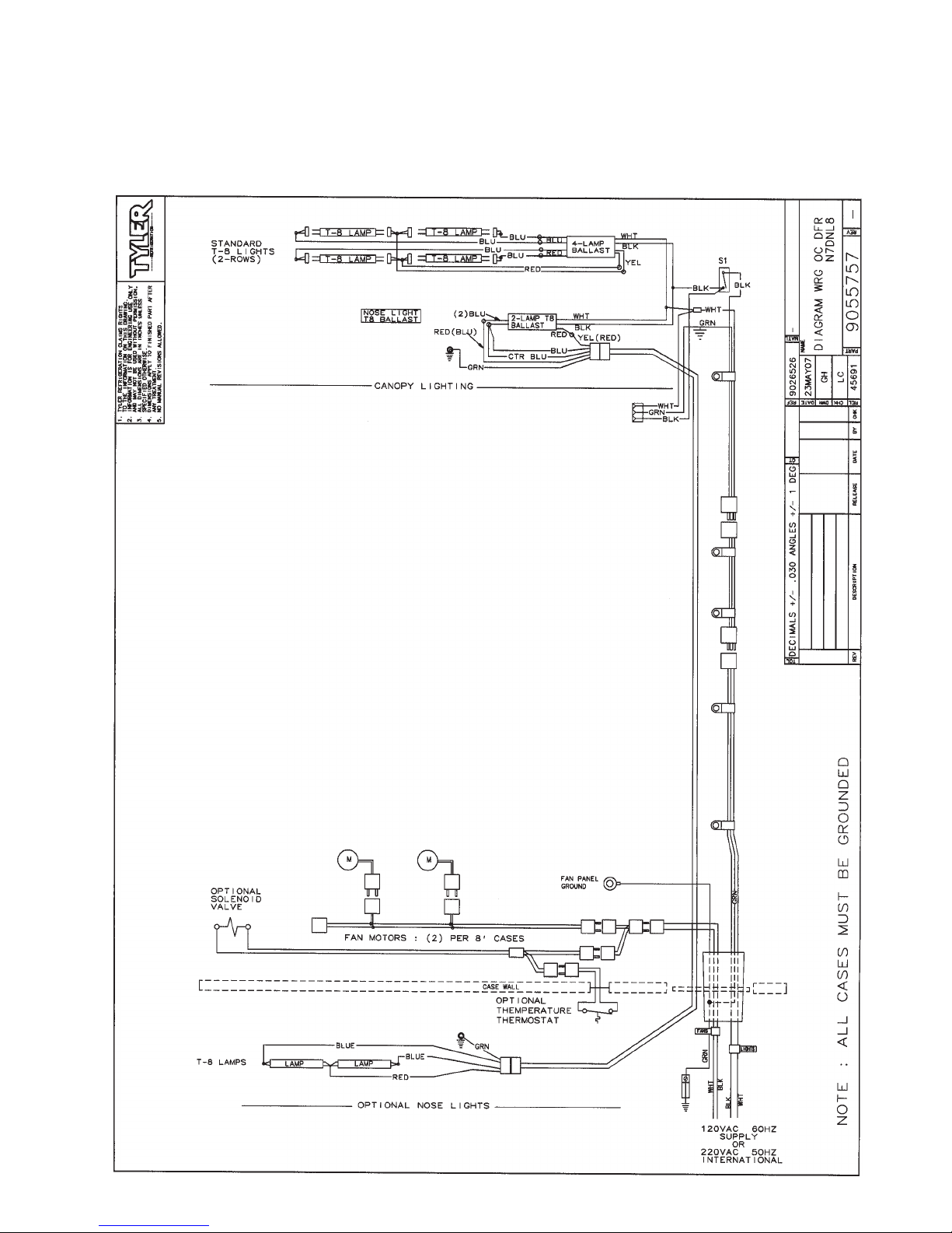
Fluorescent Lamp Circuit
The standard lighting for N7DNL and NHD
cases is 2 rows of T-8 canopy lights. Optional
T-8 Nose Light is available on all models,
while T-8 shelf lighting is only available on
the NHD models.
Defrost Information
See “General-UL/NSF I&S Manual” for
operational descriptions for each type of
defrost control.
Defrost Control Charts
N7DNL Models
Defrost
Defrost Defrosts Duration Term.
Type Per Day (Min) Temp.
Off Time 6 19 ------
The N7DNL cases do not have any klixons.
NHD Models
Defrost
Defrost Defrosts Duration Term.
Type Per Day (Min) Temp.
Off Time 4 24 ------
Electric 4 24 41°F
Gas 4 15 55°F
Most klixons are located on the right end of
the evaporator coil.
NOTE
The Gas Defrost Termination klixon is
located at the by-pass check valve.
CAUTION
If electronic sensors are used in place of
the klixons, the sensors must be located in
the same location as the klixons for that
defrost type. Any other locations will
effect the refrigeration efficiency of the
case.
June, 2007Page 8

Page 9June, 2007
WIRING DIAGRAMS
ELECTRICIAN NOTE - OVERCURRENT PROTECTION
120V circuits should be protected by 15 or 20 Amp devices per the requirements noted on the cabinet
nameplate or the National Electrical Code, Canadian Electrical Code - Part 1, Section 28. 208V defrost circuits
employ No. 12 AWG field wire leads for field connections. On remote cases intended for end to end line-ups,
bonding for ground may rely upon the pull-up bolts.
N7DNL Domestic & Export (50 Hz) Case Circuits (8’ Cases)

June, 2007Page 10
N7DNL Domestic & Export (50 Hz) Case Circuits (12’ Cases)

June, 2007 Page 11
NHD(L, M) Domestic & Export (50 Hz) Case Circuits (6’ & 8’ Cases)

Page 12 June, 2007

June, 2007 Page 13
NHD(L, M) Domestic & Export (50 Hz) Case Circuits (12’ Cases)

Page 14 June, 2007

Installation & Service Manual N7DNL, NHD
June, 2007 Page 15
CLEANING AND SANITATION
Component Removal and
Installation Instructions for
Cleaning
Shelves and Shelf Brackets
1. Remove product from shelves.
2. If shelf has a light, unplug the light cord
from the socket in the rear duct panel.
Completely insert socket cover in the light
socket to protect the receptacle.
3. Push shelves back and then lift up and out
to remove them from the shelf brackets.
4. Remove shelf brackets from slots in rear
uprights.
5. After cleaning, replace in reverse order.
Bottom Trays
1. Remove product from bottom of case.
2. Grasp and lift out each of the bottom trays
from the case interior.
3. After cleaning, replace in reverse order.
Front Air Ducts
1. Remove lower trays, see this page.
2. Lift out front air duct sections.
3. After cleaning, replace in reverse order.
Rear Duct Panels
(w/o Shelf Light Sockets)
1. Remove shelves and bottom trays, see
above.
2. Remove mounting screws and rear duct
panels from case.
3. After cleaning, replace and secure rear
duct panels in reverse order.
(with Shelf Light Sockets)
1. Remove shelves and bottom trays, see
above.
2. For cases with 5 rows of lighted shelves,
remove screw above top shelf socket and
push socket assembly back through the
hole in the rear duct panel.
3. Remove mounting screws from rear duct
panel.
4. Slowly lift out rear duct panel until the
shelf harness connector near the top of
the panel can be accessed.
5. Disconnect shelf harness connector and
complete removing the rear duct panel.
WARNING
Rear duct panels with electrical recepta-
cles can be cleaned without removing the
electrical receptacles. Do not get moisture
on electrical wires when cleaning under
this cover. Moisture on wires could cause
premature product failure and/or personal
injury or death from electrical shock.
6. After cleaning, reconnect the shelf
harness connector: install the top socket
assembly: replace and secure rear duct
panels in reverse order.
Discharge Air Honeycomb
1. Loosen screws securing rear retainer
plate.
NOTE
Note position of the honeycomb grid
during removal so it can be reinstalled the
same way.
2. Slide rear retainer plate back until the
honeycomb grid sections can be removed
from the top duct.
CAUTION
Improper installation of the honeycomb
grid section could result in improper air
flow and/or poor refrigeration.
3. After cleaning, replace honeycomb grid
sections as they were removed and
secure with the rear retainer plate and
screws.
Top Duct
1. Remove shelves and shelf brackets, see
above.
2. Remove screws, rear retainer plate and
honeycomb grid sections from top of
case.
3. Remove screws and top duct from case.
4. After cleaning, replace top duct and
remaining components in reverse order.

N7DNL, NHD
Page 16 June, 2007
Front Cladding
1. Remove front kickplate and raceway cover. (See General-UL/NSF I&S Manual.)
2. Remove color band, bumper and bumper retainer from the case. (See General-UL/NSF I&S
Manual.)
3. Remove screws for top and bottom of front cladding and remove cladding.
4. After cleaning, replace front cladding and remaining front components in reverse order.
Cleaning Instructions
WARNING
TYLER Refrigeration does not recommend the use of high pressure cleaning equipment on
display cases!! High pressure cleaners can penetrate and/or damage joint seals. Damaged
seals allow water leaks and/or air leaks that can cause poor case refrigeration.
CAUTION
• When cleaning this case, try not to introduce water into the case faster than it can be
carried away by the waste outlet.
• Liquid chlorine bleach is corrosive to metals. The use of bleach or products containing
bleach will damage metal surfaces and void the case warranty.
• Sanitize the case with Quaternary Ammonium Solutions (ex: KAYQUAT II,
J-512 Sanitizer, SANIQUAT 512, etc...) approved per 21CFR 178.1010, followed by ade-
quate draining and air drying. These solutions may be obtained from Kay Chemical Co.,
Johnson Wax Professional, Coastwide Laboratories, etc....
• Always use a soft cloth or sponge with mild detergent and water to clean any glass.
Never use abrasives or scouring pads to clean glass. They can scratch and/or damage
the glass.
See “General (UL/NSF) I&S Manual” for case cleaning instructions.
Stainless Steel Cleaning Methods
The cleaning data in the following stainless steel cleaning chart was supplied by AISI. The information was supplied by
Prime Metals Division, Alumax Aluminum Corporation.
TYPE OF CLEANING CLEANING AGENT* APPLICATION METHOD** EFFECT ON FINISH
Routine cleaning Soap, ammonia or deter- Sponge with cloth, then Satisfactory for use on all
gent and water. rinse with clear water and finishes.
wipe dry.
Smears and finger- Arcal 20, Lac-O-Nu, Lumin Rub with cloth as directed Satisfactory for use on all
prints Wash O’Cedar Cream on the package. finishes. Provides barrier film
Polish, Stainless Shine
Stubborn spots and Allchem Concentrated Apply with damp sponge or Satisfactory for use on all
stains, baked-on Cleaner cloth. finishes.
splatter, and other light
discolorations Samae, Twinkle, or Cameo Rub with damp cloth. Satisfactory for use on all
Copper Cleaner finishes if rubbing is light.
Grade FFF Italian pumice, Rub with damp cloth. Use in direction of polish lines
whiting or talc on No. 4 (polished) finish.
May scratch No. 2 (mill) and
No. 7 and 8 (polished) finishes.

Installation & Service Manual N7DNL, NHD
June, 2007 Page 17
TYPE OF CLEANING CLEANING AGENT* APPLICATION METHOD** EFFECT ON FINISH
Liquid NuSteel Rub with dry cloth. Use a Use in direction of polish lines
small amount of cleaner. on No. 4 (polished) finish.
May scratch No. 2 (mill) and
No. 7 and 8 (polished) finishes.
Paste NuSteel or DuBois Rub with dry cloth. Use a Use in direction of polish lines
Temp small amount of cleaner. on No. 4 (polished) finish.
May scratch No. 2 (mill) and
No. 7 and 8 (polished) finishes.
Cooper’s Stainless Steel Apply with damp sponge or. Use in direction of polish lines
Cleaner, Revere Stainless cloth. on No. 4 (polished) finish.
Steel Cleaner May scratch No. 2 (mill) and
No. 7 and 8 (polished) finishes.
Grade F Italian pumice, Steel Rub with a damp cloth. Use in direction of polish lines
Bright, Lumin Cleaner, Zud or on No. 4 (polished) finish.
Restoro May scratch No. 2 (mill) and
No. 7 and 8 (polished) finishes.
Penny-Brite or Copper-Brite Rub with a dry cloth. Use a Use in direction of polish lines
small amount of cleaner. on No. 4 (polished) finish.
May scratch No. 2 (mill) and
No. 7 and 8 (polished) finishes.
Heat tint or heavy Penny-Brite or Copper-Brite Rub with a dry cloth. Use in direction of polish lines
discoloration on No. 4 (polished) finish.
May scratch No. 2 (mill) and
No. 7 and 8 (polished) finishes.
Paste NuSteel or DuBois Rub with dry cloth. Use a Use in direction of polish lines
Temp small amount of cleaner. on No. 4 (polished) finish.
May scratch No. 2 (mill) and
No. 7 and 8 (polished) finishes.
Revere Stainless Steel Apply with a damp sponge Use in direction of polish lines
Cleaner or cloth. on No. 4 (polished) finish.
May scratch No. 2 (mill) and
No. 7 and 8 (polished) finishes.
Allen Polish, Steel Bright, Rub with a damp cloth. Use in direction of polish lines
Wyandotte or Zud on No. 4 (polished) finish.
May scratch No. 2 (mill) and
No. 7 and 8 (polished) finishes.
Burnt-on foods and Easy-Off, De-Grease-It, 4-6% Apply generous coating. Excellent removal, satisfactory
grease, fatty acids, hot solution of such agents Allow to stand for 10-15 min. for use on all finishes.
milkstone (where swab- as trisodium tripolyphospate, Repeated application may
bing or rubbing is not or 5-15% caustic soda be necessary.
practical) solution
Tenacious deposits, Oakite No. 33, Dilac, Texo 12, Swab and soak with clean Satisfactory for use on all
rusty discolorations, Texo N.Y., Flash-Klenz, cloth. Let stand 15 minutes finishes.
industrial atmospheric Caddy Cleaner, Turco Scale or more according to direc-
stains 4368 or Permag 57. tions on package. Rinse
and dry.
Hard water spots Vinegar Swab or wipe with a cloth. Satisfactory for use on all
and scale Rinse with water and dry. finishes.
5% oxalic acid, 5% sulamic Swab or soak with a cloth. Satisfactory for use on all
acid, 5-10% phospheric acid, Let stand 10-15 minutes. finshes. Effective on tenacious
or Dilac, Oakite No. 33, Always follow with neutralizer deposites or where scale has
Texo 12 or Texo N.Y. rinse, and dry. built up.

N7DNL, NHD
Page 18 June, 2007
GENERAL INFORMATION
NSF Product Thermometer
Installation
1. Unwrap the thermometer and bracket
assembly shipped loose with the case.
NOTE
Recommended bottom tray position is with
the lips up.
2. Position bracket in front right corner of the
right-most bottom tray. Making sure the
bracket is flush with the right edge, use
the bracket holes as a template for where
to drill the holes.
3. Drill two .196” holes in the bottom tray.
NOTE
For ease of installation, position the
washers and capnuts on the top side of
the bracket and bottom tray.
4. Mount the bracket to the bottom tray with
two screws, washers and capnuts.
Egg Merchandiser Kit
(All Models)
All egg shelves come galvanized or stainless
steel. The upper egg shelves are 15” x 48”
and come with 82 degree fixed white brackets.
The brackets are available in one position
only. The upper egg shelves assemblies
include a rear air close-off.
Tilted base egg shelves come in 4’ modules.
They are designed and notched to fit inside
the existing 2’ bottom trays.
NOTE
Egg shelves are designed to catch and
hold spilled liquids so they can be cleaned
up before getting further into the case. If
the tilted base shelves are used upside
down, improper shelf support will result
causing the middle of each shelves to sag.
Upside down usage also allows drippage
to get into the case making cleaning very
difficult. Good sanitation is essential for
egg merchandising.
TYPE OF CLEANING CLEANING AGENT* APPLICATION METHOD** EFFECT ON FINISH
Grease and oil Organic solvents such as Rub with a cloth. Organic Satisfactory for use on all
carbon tetrachloride, tri- solvents may be flammable finishes.
chlorethylene, acetone, kero- and/or toxic. Observe all
sene, gasoline, benzene, precautions against fire.
alcohol and chlorethane n.u. Do not smoke while vapors
are present. Be sure area
is well ventilated.
*Use of proprietary names is intended only to indicate a type of cleaner, and does not constitute an endorsement, nor is
omission of any proprietary cleanser to imply its inadequacy. It should be emphasized that all products should be used
in strict accordance with instructions on package.
** In all applications a sponge or fibrous brush or pad are recommended. DO NOT use ordinary steel wool, steel brushes,
chlorine bleach or products containing bleach for cleaning or sanitizing stainless steel.

Installation & Service Manual N7DNL, NHD
June, 2007 Page 19
Figure 2 shows
what happens to
the air flow when
the shelves are
removed. The air
drifts back to the
rear duct and
swirls about. This
breaks the protec-
tive barrier, caus-
ing the case air to
mix with ambient
air to a great
extent.
Peg Bar Information
The hang up blister pack has become a standard means of marketing sliced luncheon meats and
other delicacies. It appears that all that is needed to adapt multi-shelf cases for these packages
is to add peg bars and pegs. However, it isn’t quite that simple, because the removal of shelves
changes more than the appearance of the case.
Figure 1 shows
the air flow in
a Multi-Deck dis-
play merchandiser
with shelves. Air
flow from the top
and back forms a
protective barrier
to ambient air.
Figure 4 shows the
proper air flow for
cases with peg
bars. The addition
of a baffle above
each row of peg
bars, except the
top row and a bot-
tom shelf, maintains
proper air flows
and temperatures
in the case. Non-
load bearing air
baffles should run
the same width as
the peg bars.
Figure 3 depicts what happens to the air flow
in a case full of peg bars. The air falls through
openings between packages and fails to main-
tain a protective
barrier. When the
bars are fully
stocked, the effect
is minimized, but
product tempera-
tures will not be
as good as they
could be. Sweating
may be noticed on
the top duct panel
above the bars.
The coil will also
frost faster, requiring
more frequent
defrosts.
CAUTION
Always use one row of shelves below the lowest row of peg bars. Use air baffles above
each row of peg bars, except the top row. The air baffle should be solid in design and
positioned 1” in front of the rear duct and 5.5” back from the rear edge of the card
moulding. This provides and maintains the protective air flow in the case and proper
product cooling and storage.

N7DNL, NHD
Page 20 June, 2007
Peg Bar Information for Cannon
Magna Bar Peg Bar Display
Systems (TYLER supplied)
Air baffle shelves should always be used
with peg bars for hanging meat displays.
Air baffle shelves are non-load bearing and
are used only to help direct the air flow. The
air baffles should be installed above each row
of peg bars, except the top row, along with a
bottom shelf. Air baffles are available from
TYLER that are compatible with 15” offset
support arms.
1. 48” peg bar with 52 holes to accept pegs.
Flat side of holes in peg bar must be down
and to the front of the bar. Attach two hook
brackets to peg bar with two clamp brackets
and four screws. Position and install peg bar
in slotted holes in back of case.
2. 15” pegs and offset support arms lock in
place on the peg bar.
After marking the desired locations in the peg
bar, install the pegs into peg bar holes. Hold
peg at 90° angle to peg bar. Insert peg into
hole in peg bar. Rotate peg until angled end
points up. Pull peg out until peg sits properly
in the peg bar.
Offset support arms must be installed in the
peg bar so the notches in the air baffle can fit
over them. Install support arms in the same
manner as the pegs (with offset up).
3. Non-load bearing air baffle should run the
same width as the peg bar. Air baffle
rests on the two offset support arms. The
notches in the air baffle must fit over the
support arms. NOTE: The air baffle
should be solid in design and posi-
tioned 1” in front of the rear duct and
5.5” back from the rear edge of the
card moulding.
4. Card moulding is offset 2” in front and
3/4” above the pegs.
Slide the card moulding onto the two offset
support arms. Center the card moulding so it
is aligned with the peg bar. Secure the card
moulding on the offset support arms with two
spring clips. To remove card moulding,
squeeze each spring clip together until the
card moulding releases.
This manual suits for next models
6
Table of contents
Other Tyler Refrigeration Merchandiser manuals
Popular Merchandiser manuals by other brands

Hussmann
Hussmann Impact Excel D5X-ULEP Installation and service manual

Hatco
Hatco FLAV-R-FRESH FDW-1 Brochure & specs

Hussmann
Hussmann IMPACT CW2-EGE Technical data sheet

VALERA
VALERA QUADRATO RG datasheet

Silver King
Silver King SKCTM Technical manual and parts list

Hussmann
Hussmann Impact Excel C2X-E Technical data sheet

Alto-Shaam
Alto-Shaam HALO HEAT 750-GDU Installation operation & maintenance

Turboair
Turboair TGM-11RV Installation and operation manual

Alto-Shaam
Alto-Shaam HSM-38/3S Specification sheet

Hussmann
Hussmann CIDM-I Installation and operation guide

King Edward
King Edward HFMV instruction manual

Hussmann
Hussmann P2NX-EP Technical data sheet