Refrigeration Procedures
See “General-UL.NSF I&S Manual” for gen-
eral system, control and superheat infor-
mation.
Optional Dual Temperature Control
The dual temperature control unit is a factory
installed option. This control allows the user
to easily switch from medium to low tempera-
ture operation by flipping a switch. The dual
temperature control consists of an EPR valve
in the suction line coming off the evaporator.
The EPR valve can be bypassed with a sole-
noid controlled bypass line around it. The
toggle switch opens or closes this solenoid.
When the solenoid is open, the evaporator is
connected directly to the compressor suction
that allows for low temperature operation.
When the solenoid is closed, the evaporator
must operate through the EPR valve which
has been preset to the desired medium
temperature.
EXAMPLE: R-404A system with 12 psig
of suction pressure. With the suction line
solenoid open, the coil pressure operates at
12 psig with a temperature of -29°F. When
the toggle switch is flipped, the solenoid
closes directing the flow through the EPR
valve. If the EPR valve is set for 48 psig, the
evaporator will see a coil temperature of 12°F
and will operate at a discharge air tempera-
ture of about 22°F.
When gas defrost is used, an additional
check valve is mounted around the EPR valve
to allow reverse flow for the defrosting gas. A
fan delay is also connected with gas defrost
to cycle the fans off, but only during the
medium temperature mode.
Electrical Procedures
Electrical Considerations
CAUTION
Make sure all electrical connections are
tight. This prevents burning of electrical
terminals and/or premature component
failure.
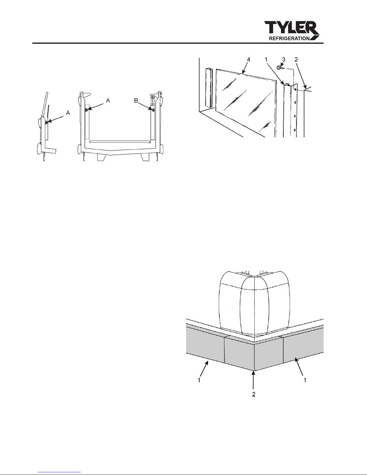
NOTE
The raceway houses the electrical wiring
and components for the case. All raceway
covers will be shipped loose.
Case Fan Circuit
This circuit is to be supplied by an uninter-
rupted, protected 120V circuit. The case fan
circuit is not cycled, except when equipped
for gas defrost. On gas defrost cases the fan
circuit is controlled by a 50/40 klixon when
used for medium temperatures.
NOTE
With gas defrost, the fans will not start
until the coil temperature reaches 40°F at
the fan delay klixon.
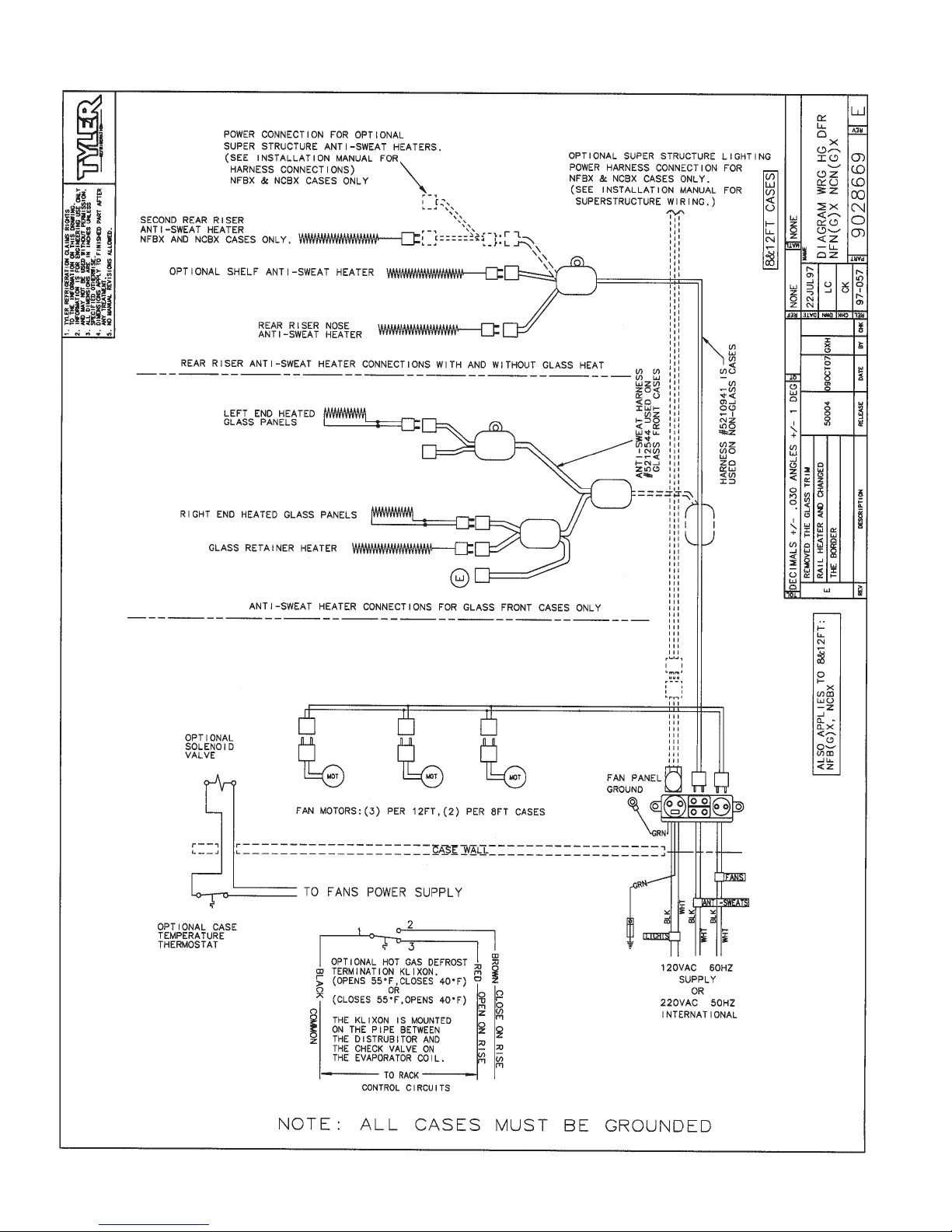
Anti-Sweat Circuit
All cases have at least one anti-sweat heater
in each discharge air grid and return air grid.
Cases with glass have an additional anti-
sweat heater under the glass retainer. Anti-
sweat heaters are wired directly to the main
power supply so they can operate at all
times.
Installation & Service Manual
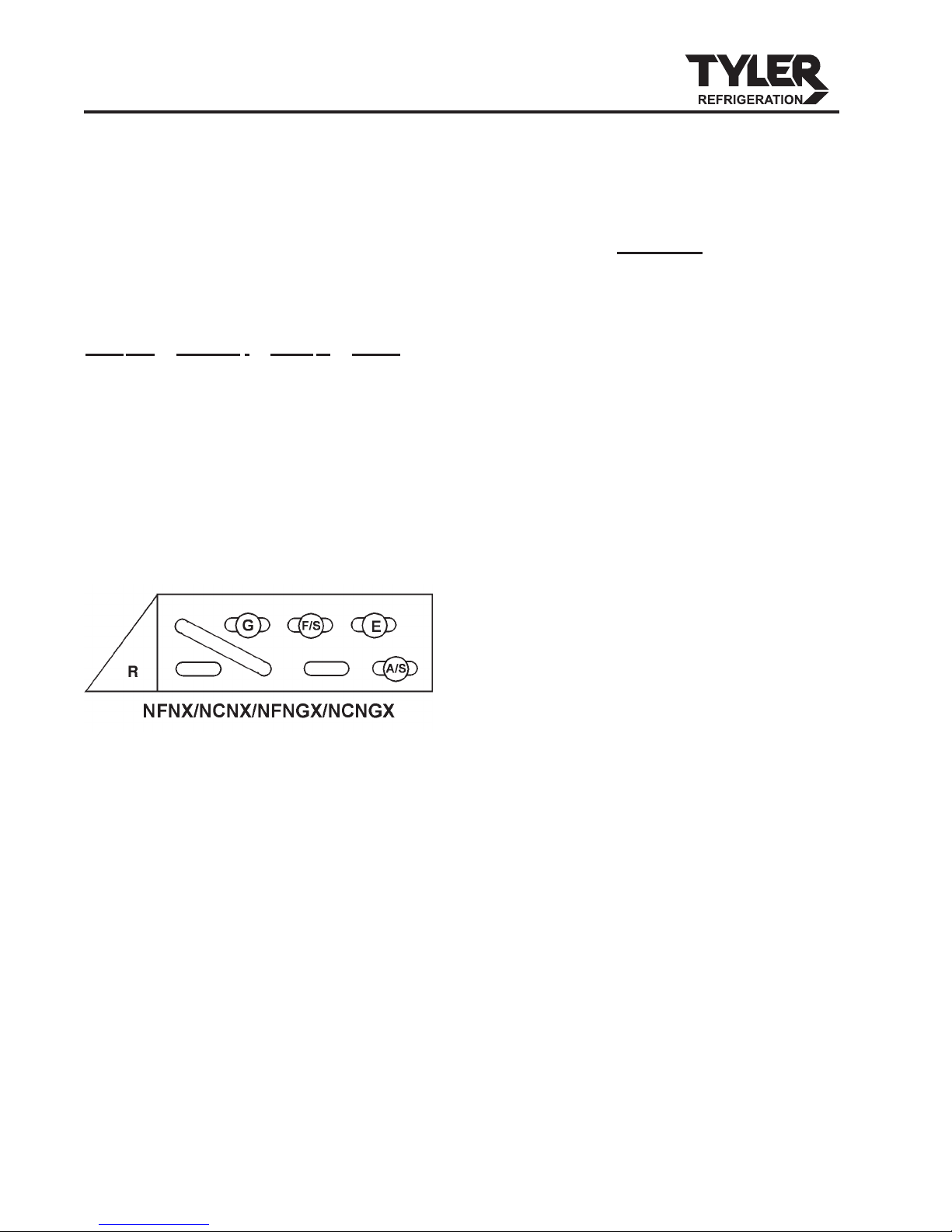
NFNX, NCNX, NFNGX,
NCNGX
November, 2007 Page 7