SAFETY
Understand that your safety and the safety of
other persons is measured by how you service
and operate this backhoe. Know the position
and operations of all controls before you they
to operate. Make
MakeMake
Make sure
suresure
sure you
youyou
you check
checkcheck
check all
allall
all controls
controlscontrols
controls
in all safe area before starting.
in all safe area before starting.in all safe area before starting.
in all safe area before starting.
Read
ReadRead
Read this
thisthis
this manual
manualmanual
manual completely
completelycompletely
completely and
andand
and thoroughly
thoroughlythoroughly
thoroughly
and make sure you understand all controls. All
equipment has a limit. Make sure you are aware
of the stability and load characteristics of this
backhoe before you begin operation.
The safety information given in this manual
does not replace any safety codes, insurance
needs, federal, state and local laws. Make
sure your machine has the correct equipment
required by your local laws and regulations.
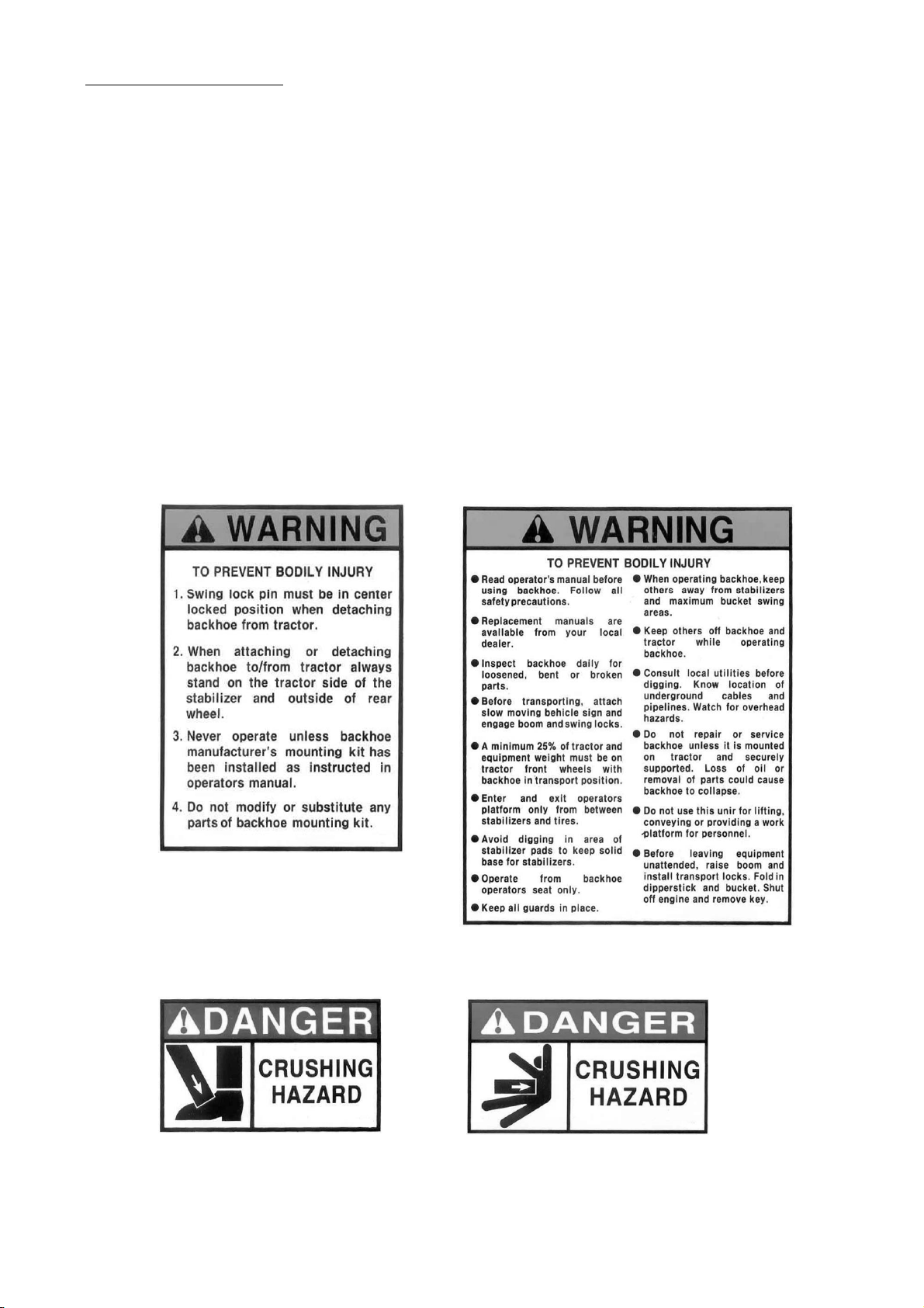
This safety alert symbol indicates important safety messages in this manual.
This safety alert symbol indicates important safety messages in this manual. This safety alert symbol indicates important safety messages in this manual.
This safety alert symbol indicates important safety messages in this manual.
When you see this symbol, carefully read the message that follows and
When you see this symbol, carefully read the message that follows and When you see this symbol, carefully read the message that follows and
When you see this symbol, carefully read the message that follows and
be alert to the possibility of personal injury or death.
be alert to the possibility of personal injury or death. be alert to the possibility of personal injury or death.
be alert to the possibility of personal injury or death.
SAFETY PRECAUTIONS
SAFETY PRECAUTIONSSAFETY PRECAUTIONS
SAFETY PRECAUTIONS
Before starting the engine of your tractor,
make sure all operation controls are in park
lock or neutral position.
Stop the backhoe arms gradually when lowering
or lifting loads.
- 4 -
Before applying hydraulic pressure, make sure
all hydraulic connections are tight and
components are in good condition.
When using remote hydraulic tractor valves on
some tractors, the backhoe lift and dump
cylinders will continue moving unless the
control levers are manually returned to neutral,
or until relief pressure is reached at the ends
of piston strokes. Observe the bucket
movement and maintain control with the
control levers.
Equip your tractor with a ROPS cab or frame
for your protection. See your tractor operator's
manual for correct seat belt usage.
Travel speed should be such that complete
control and machine stability is maintained at all
times. Where possible, avoid operation near
ditches, embankments and holes. Reduce
speed when turning, crossing slopes, and on
rough, slick or muddy surfaces.
A frequent cause of personal injury or death is
persons falling off and being run over. Do not
permit others to ride on your tractor. Only one
person, the operator, should be on the
machine when it is in operation.
Never use your hand to check for suspected
leaks under pressure. Use a piece of cardbord
or wood for this purpose. Escaping hydraulic oil
or diesel fuel leaking under pressure can have
have sufficient force to penetrate the skin and
cause infection or other injured by leaking fluid,
seek medical attention immediately.
Before leaving the tractor, stop the engine,
put all controls in neutral, engage the parking
brake and remove the key from the ignition.
To prevent personal injury, relieve all pressure
before disconnecting fluid lines.
lock or neutral position.
Stay off of slopes too steep for safe operation.
Shift down before you start up or down a hill
with a heavy load. Avoid "free wheeling"
Operate controls only when seated in the
operator's seat.
- 4 -