TYROLIT Hydrostress WSE2226P User manual

Operating Instructions
Control unit WSE2226
Index 000
Original operating instructions
10991502 en / 15.11.2016

Page 2
TYROLIT Hydrostress AG
Witzbergstrasse 18
CH-8330 Pfäkon
Switzerland
Tel. 0041 (1) 952 18 18
Fax 0041 (1) 952 18 00
Congratulations!
With a Hydrostress unit from TYROLIT, you have chosen a tried and tested piece of equipment
which has been designed and built to leading technical standards. Only genuine TYROLIT Hy-
drostress replacement parts can guarantee quality and interchangeability. If maintenance work
is neglected or carried out inexpertly we will be unable to honour our warranty obligations. Any
repair work must be carried out by trained personnel only.
Our after sales service is available to help ensure that your TYROLIT Hydrostress units remain in
perfect working order.
We hope that working with your TYROLIT unit will be a satisfying and fault-free experience.
TYROLIT Hydrostress
Copyright © TYROLIT Hydrostress

TYROLIT Hydrostress AG
Page 3
Safety
DANGER
Failure to comply with the safety instructions in the «Safety Manuals / System Manuals» may re-
sult in serious injuries or even death.
XMake sure that the «Safety Manuals / System Descriptions» for the relevant type of saw have
been fully read and understood.
DANGER
Death or serious injury can be caused by sudden start-up of the machine.
XBefore switching on the system, ensure that no other persons are present in the danger ar-
eas.
XSwitch the system o before connecting or disconnecting cables.
XOn leaving the system switch o and make safe so that it cannot be switched on again.
Death or serious injury as a result of the sawing machine continuing to run after an acci-
dent.
XEnsure that the EMERGENCY STOP button can be reached quickly.
Electric shock from live cables and connectors.
XSwitch o the control unit WSE2226 before connecting or disconnecting cables.
XEnsure that the power supply is earthed and tted with a residual current operated protec-
tive device (FI Type B) with a maximum residual current of 30mA.
Risk of re due to incorrect mains voltage.
XMake sure that the mains voltage and mains frequency correspond with the mains settings
of control unit WSE2226.
Action in an emergency
XPress the EMERGENCY STOP button on the remote controller.
If the EMERGENCY STOP has been activated on the radio remote controller, the LED pilot lamp
ashes quickly.
In an emergency the sawing machine can be also switched o using the main switch of control
unit WSE2226.
Emergency Stop
1
1.1

TYROLIT Hydrostress AG
Page 4
Description
Main components Control unit
1 Operating hours counter 8 Main motor connection
2 Main switch 9 Name plate
3 Feed motor connection 10 Indicator lights
4 Remote controller connection 11 Mains system selection button
5 Mains connector 12 Reset button
6 Water nipple / water inlet 13 Radio remote controller
7 Water connection / water outlet
Main components of radio remote controller
Main components of remote controller
1 Feed potentiometer 8 Pulse switch Control unit
2 On / O Main motor 9 EMERGENCY STOP
3 Main motor potentiometer 10 Indicator lights
4 Water On / O 11 Warning light (radio & battery)
5 Diameter selector switch 12 Position lock switch (Traverse feed)
6 Traverse feed joystick 13 Casing
7 Starter switch
2
2.1
2.2

TYROLIT Hydrostress AG
Page 5
Remote controller
The remote controller can be replaced by an accumulator or a battery operated radio remote
controller. The remote controller can also be operated using a cable.
Radio remote controller
The transmitter and receiver are a pair of matched units. They cannot be used with other devices.
Transmitter = radio remote controller
Receiver = control unit
Remote controller
Operating modes
Rechargeable battery operation:
The interchangeable rechargeable battery is inserted in the base of the casing. The operating
period with a fully charged battery is approximately 12 hours. A shorter operating period can
be expected at low temperatures. The reception distance is 25 m.
Battery operation:
The battery holder is included in the scope of supply and allows operation with three 1.5 V AA
batteries. The reception distance is 25 m.
Cable operation:
The cable insert is included in the scope of supply and allows connection of the remote control-
ler to the control unit WSE2226. The cable length is 10m. Cable operation makes it possi-
ble to work in areas where radio operation is not allowed (e.g. hospitals).
With cable operation all control signals are transmitted via the power cable.
The rechargeable/ordinary battery holders may not be inserted in the base of the casing during
cable operation.
2.3
2.4

TYROLIT Hydrostress AG
Page 6
Accessories for remote controller
The battery charger is exclusively for recharging the interchangeable rechargeable battery. The
battery holder must not be inserted.
Accessories
1 2x Interchangeable rechargeable batteries No. 10984306
2 Rechargeable battery charger No. 10984305
Rechargeable battery charger with
10-30 VDC connection
No. 10984840
3 Remote control cable No. 10991362
4 Battery holder No. 10984307
5 Key No. 10984309
During cable operation no interchangeable rechargeable battery or battery holder must be in-
serted into the remote controller.
2.5

TYROLIT Hydrostress AG
Page 7
Connections
Connecting remote controller and motor connections
9The control unit is isolated from the power supply
9Connectors/plugs are clean
9Cables are undamaged
X
Connecting the mains and water supply
9The power supply is earthed and tted with a residual current operated protective device
(FI Type B; max. residual current 30mA)
9Cable cross-section is sucient: for up to 25 m long 5 x 6 mm2, more than 25 m long 5 x 10 mm2
3
3.1
3.2

TYROLIT Hydrostress AG
Page 8
Operation
Overview of operating elements
Controls
1 Position lock switch (Traverse feed) 8 Main motor potentiometer
2 Water On / O 9 Diameter selector switch
3 EMERGENCY STOP 10 Feed joystick
4 Pulse switch control unit 11 Main switch Control unit
5 Starter switch 12 Reset button
6 Feed potentiometer 13 Mains system selection button
7 On / O, main motor
4
4.1

TYROLIT Hydrostress AG
Page 9
Starting the control unit WSE2226
CAUTION
The control unit WSE2226 can be damaged if it slips or overturns!
XMake sure that the control unit WSE2226 stands horizontally (handle at top).
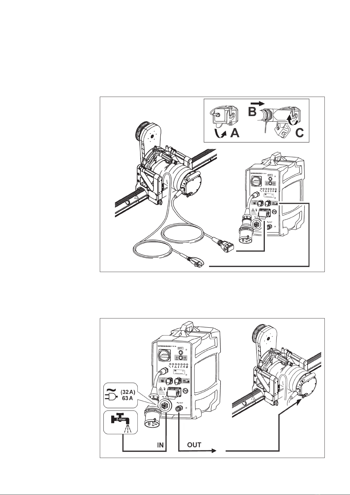
9Control unit WSE2226 is connected to the mains and the water supply.
9The sawing machine is connected to the control unit WSE2226.
9The remote controller EMERGENCY STOP has been deactivated.
9The control unit WSE2226 is not exposed to direct sunlight.
Starting the control unit WSE2226
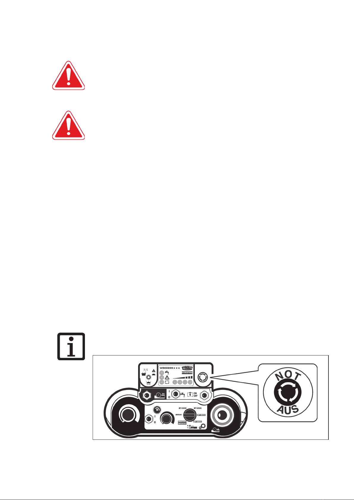
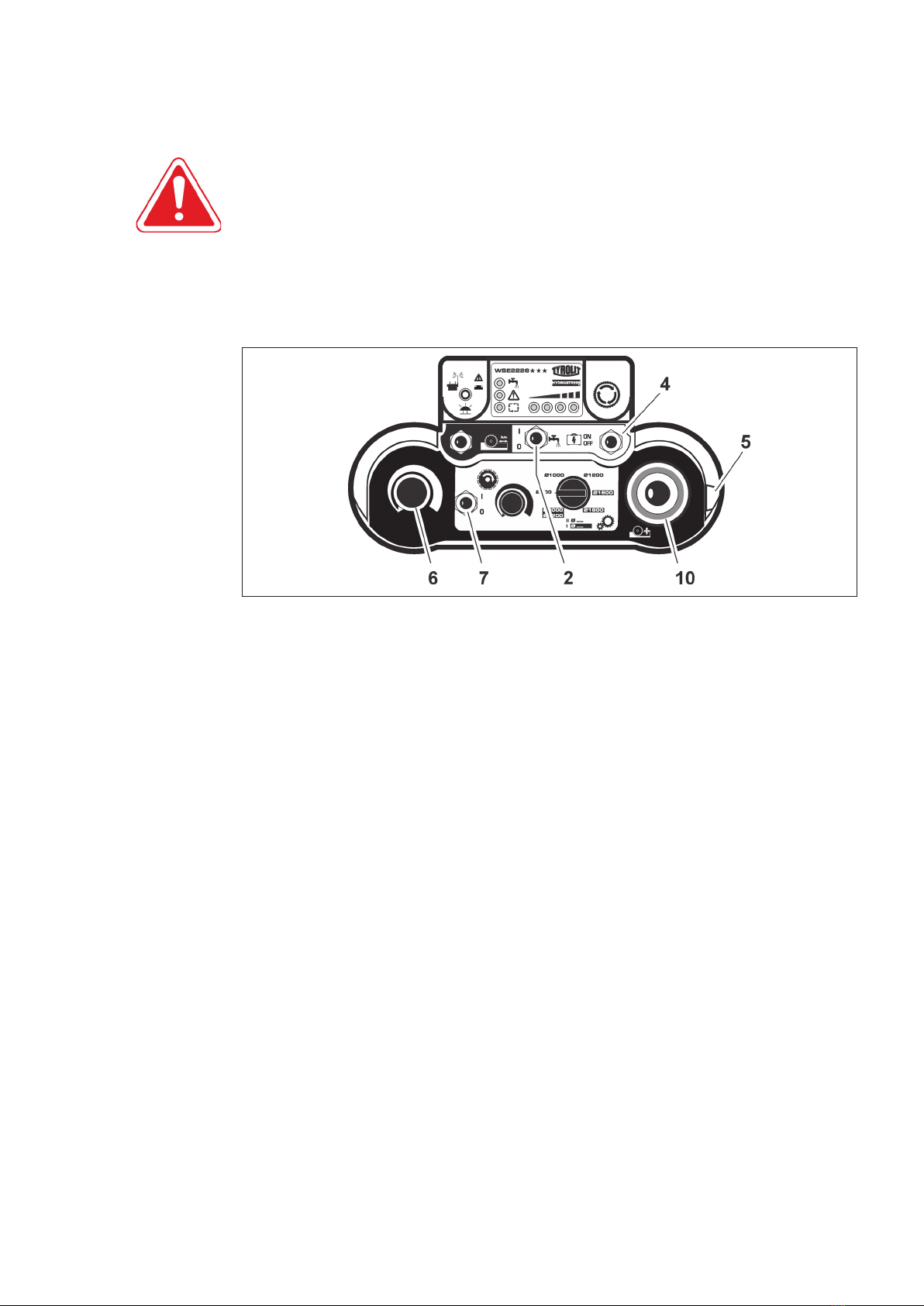
XMove the controls shown below on the remote controller to the 0 position.
Feed potentiometer (6)
Starter switch (5)
Feed joy stick (10)
Main motor On/O (7)
XSwitch on the control unit WSE2226 using the main switch (11).
XSwitch on the radio remote controller using the starter switch (5).
–Warning lights (radio and battery) at rst show red
–An audible signal sounds simultaneously
–Indicators ash coloured
–Second audible signal sounds
–Indicators show coloured
–Warning light ashes green
XPress the pulse switch (4) on the radio remote controller briey to the ON-position.
All indicator lights except the warning light and the group alarm on the radio remote con-
troller go o.
XPress the reset button (12) on the control unit.
XPress the remote control pulse switch (4) briey in the ON-position.
The the control unit 'ready' lights show green.
XOpen the water valve on the system supply line.
XPress the Water On/O switch (2) on the remote control unit to I.
–Water ows from the cutting tool
XPress the main motor On/O switch (7) on the remote controller to position I.
–The electric motor starts when the main motor potentiometer is in the max. position.
XThe control unit WSE2226 has started up and is ready for operation.
4.2

TYROLIT Hydrostress AG
Page 10
Remote control frequency change
The remote control systems are equipped with a frequency generator for frequency selection.
If the systems malfunction or the radio link is interrupted (another transmitter, range, empty
battery), the systems immediately go into EMERGENCY OFF mode.
New frequency search:
You can select the next frequency by switching the start switch on the remote control o and
back on.
The o/on switching procedure is limited to four attempts (channels). If the system has not
found a suitable frequency after four attempts, you must change to cable operation.
4.2.1

TYROLIT Hydrostress AG
Page 11
Selecting mains network
The control unit WSE2226 is preset for a 63A power supply network (63A button lights
up). It is possible to switch over to a 32A power supply network. The system automatically
returns to the 63A settings when it is restarted.
XTo set the power supply network to 32A press the power network selector (13), the button
light goes out.
Resetting must take place directly after switching on the control unit WSE2226.
Tool soft start
The control unit WSE2226 provides a facility for a tool soft start.
Proceed as follows:
XStarting the control unit WSE2226, see 4.2.
XTurn the main motor (8) potentiometer to the 0 position.
XPress the switch main motor (7) to I.
XSelect the desired output level, see 4.5.
XTurn the main motor (8) potentiometer slowly to 100% power.
Selecting tool station
After the control unit WSE2226 has been started correctly the tool station can be selected.
Selecting the power level
Proceed as follows:
XSet the diameter selector switch to the desired tool and turn the main motor potentiometer
from 0 to 100%.
XCheck gear at gearbox of drive motor.
The tool stations may not be changed during operation.
The tool stations are set with reference to the tool diameter for the optimum rotational speed
and cutting performance.
The rotational speed can be reduced using the main motor potentiometer but at the same time
the power is reduced.
4.3
4.4
4.5

TYROLIT Hydrostress AG
Page 12
Power control
The main motor and the feed motor power are controlled via the potentiometers.
Power control
Feed motor potentiometer (6)
Main motor potentiometer (8)
Adjusting the feed
The feed movements are selected with the joystick.
Adjusting the feed
During the cutting process the feed speed is automatically assisted by a feed facility.
4.6
4.7

TYROLIT Hydrostress AG
Page 13
Manually adjusting the feed speed
9Control unit WSE2226 has started
XSelect the required feed speed via the feed potentiometer (6).
Feed stop
So that the joystick does not have to be held in position during the travel feed motion the travel
feed can be locked.
Proceed as follows:
XPush the joystick in the desired travel direction and at the same time press the locking
switch (1).
XWhen the joystick and the locking switch are released the feed is locked.
In order to release the feed lock, move the joystick slightly in any desired direction.
Switching o the control unit WSE2226
Proceed as follows:
XSwitch o electric motor (7) On / O main motor.
XTurn o cooling water, switch (2) Water On / O.
XClose water valve on control unit WSE2226.
XTurn the start switch (5) on the remote controller to the 0 position.
XSwitch o the control unit WSE2226 using the main switch (11).
Only stop the wall saw WSE2226 using the EMERGENCY STOP function in an emergency.
CAUTION
Frost damage to control unit WSE2226!
Heat damage to control unit WSE2226!
XBlow out any water if there is a risk of frost (see chapter 4.9, Blowing out water).
XDirect sunlight on the WSE2226 control unit must be avoided.
Blowing out the water
9Main switch is set to OFF
XDisconnect the mains plug.
XDisconnect all water lines.
XConnect blow out pump to the water nipple.
XBlow out water until all of the cooling water has been removed.
XRemove the pump.
4.7.1
4.7.2
4.8
4.9

TYROLIT Hydrostress AG
Page 14
Deactivating EMERGENCY STOP
If the EMERGENCY STOP is activated on the radio remote controller, the radio and battery light
(8) ashes.
Deactivating EMERGENCY STOP
The following controls must be moved the 0 position:
Feed potentiometer (6).
Feed joy stick (10).
Main motor On/O (7).
Turn the EMERGENCY STOP button (3) clockwise.
Press pulse switch control unit (4) to the ON position.
After termination of work
Proceed as follows:
XTurn the main switch on the control unit WSE2226 to the 0-position.
XWithdraw the mains plug (Control unit WSE2226).
XDisconnect the water hoses from control unit WSE2226.
XBlow out the water from all the lines (blow out pump).
XDisconnect electric cable.
XClean the control unit WSE2226, the remote controller and the cable with a damp
cloth.
Cleaning using high pressure cleaning equipment is not permitted.
Products containing cleaning agent can damage parts of the control unit WSE2226, the
radio remote controller and the cable.
4.10
4.11

TYROLIT Hydrostress AG
Page 15
Reacting to displays
Symbols on the control unit / remote controller
Symbols on the control unit Symbols on the remote controller
1 Service 8 Radio and battery remote control
2 Control unit external fault 9 Cooling water
3 Fault within the control unit 10 Group alarm
4 Temperature 11 Ready for operation lights
5 Mains connector
6 EMERGENCY STOP
7 Potentiometers
5

TYROLIT Hydrostress AG
Page 16
Power and error displays on the control unit
Symbol Response Possible cause Action
Lights up red After the rst 100 operating
hours, then after every 200 op-
erating hours.
Carried out only by TYROLIT Hydrostress AG
or an authorised representative
Lights up red Fault:
- current overload
- short circuit
- earth fault Main motor
- defective feed motor
The control unit will not start.
XCheck network connection.
XCheck cable.
XReplace feed motors.
XContact TYROLIT Hydrostress AG customer service.
Lights up red Defective
- main contactor
- brake resistance
- over current Motor
- CAN fault
- group fault
The control unit will not start.
XContact TYROLIT Hydrostress AG customer service.
XCheck network connection.
Lights up red Over heated
- cooling element
- control unit
- main motor
The control unit will not start.
XCheck cooling. Wait until it can be restarted. Before starting
press the reset button.
XAvoid direct contact with sun light.
Lights up red Phase missing The drive unit will not start or switches o during operation.
XCheck the mains fuse in the distribution box and switch it on
if necessary.
XHave the site power supply checked.
XHave the extension cables, plugs and sockets
checked for faults.
Lights up red The EMERGENCY STOP has been
activated
- CAN fault
XDeactivate the EMERGENCY STOP.
XContact TYROLIT Hydrostress AG customer service.
Lights up red Feed potentiometer not in zero
position
The control unit will not start.
XSet the feed potentiometer to 0.

TYROLIT Hydrostress AG
Page 17
Power and error displays on the remote controller
Symbol Response Possible cause Action
Flashes red Rechargeable battery voltage
too low
XRecharge rechargeable battery.
Flashes rapidly
green
No radio connection
The EMERGENCY STOP has been
activated
XSwitch on the control unit.
XDefective receiver.
XNo receiver matched connection, see page 5.
No light shows No water ow The control unit will not start, motor does not run.
XPress the cooling water button. (LED shows blue).
Lights up red
or ashes
• Group alarm on the control
unit
• When the pulse switch control
unit is operated, the main mo-
tor On/O switch is in the po-
sition On
XObserve control unit fault indicators.
XPress the control unit reset button.
Lights up green The motor is ready to start
No light shows Contactor not ready XOperate control unit pulse switch.
Shows the current power range
Ideally: At the third, orange coloured diode (In iron fourth, red diode).

TYROLIT Hydrostress AG
Page 18
Servicing and maintenance
Cleaning using high pressure cleaning equipment is not permitted.
Cleaning using high pressure cleaning equipment can damage the control unit and the remote
controller.
Products containing cleaning agent can damage parts of the control unit WSE2226, the
radio remote controller and the cable.
Clean water lter
Clean water lter
6
Maintenance and servicing table
Before starting
up
On nishing
work
Weekly
Annually
After faults
After damage
Electrical system XCheck the condition and cleanliness
of electric cables, plugs/connectors
and switches.
X X X X
XCheck the condition and cleanliness
of connections. X X X X
Water economy XCheck water lines for cleanliness and
leaks. X X X X
XClean water lter. X X X
XBlow out the water if there is a risk of
frost. X X X
Entire WSE2226
control unit
XClean with damp cloth
no high pressure cleaner X
Service XTo be performed by TYROLIT Hydros-
tress AG or an authorised workshop.
First service after 100 operating hours
Further services after every further 200 operating hours
6.1

TYROLIT Hydrostress AG
Page 19
Faults
7
Faults
Faults Possible cause Solution
Control unit
does not run although the
mains cable is connected
Control unit is switched o XSwitch control unit on, see Chapter 4.
Mains cable is defective XReplace the mains cable.
No voltage at the power supply (build-
ing site)
XCheck the power supply.
Power supply phases incorrectly
connected
XCheck the power supply.
Phase missing See the chapter 5 entitled «Reacting to displays».
The control unit starts and
then cuts out again
Building site power supply cut-o unit
trips
XCheck and if necessary adapt the cut-o protection.
XIf necessary change the power supply.
XSee chapter entitled «Reacting to displays».
No power, even though
the control unit
is running
Incorrect voltage
Defective main motor
XMake sure that the control unit voltage and frequency
match the mains supply specications.
XContact TYROLIT Hydrostress AG customer service.
The control unit
suddenly cuts out
Over or under voltage XCheck the power supply. Refer to fault indicator.
Cross section of power supply cable too
small
XCheck the power supply.
Defective plug connection XCheck the plug connection.
XCheck the power supply.
Group alarm XRefer to fault indicator
Main motor is not running • Main motor potentiometer is in
0-position
• Defective main motor On / O switch
on remote controller
The remote controller 'ready to operate'
light does not come on.
XContact TYROLIT Hydrostress AG customer service.
XDo not start control unit, see Chapter 4.2
EMERGENCY STOP activated XDeactivate EMERGENCY STOP, see Chapter 4.10.
Overheating XCheck the water circuit and the plug-in couplings.
XRefer to fault indicator.
No water XSwitch on the water supply.
XRefer to fault indicator.
Remote controller
not working
Rechargeable battery or battery have
too little
charge
XReplace rechargeable battery and recharge or install
cable operation.
XReplace batteries.
Feed potentiometer indi-
cates no function
• Defective potentiometer in the remote
controller
• Feed motors not connected
• Defective feed motor
• Joystick is in the zero position
XContact TYROLIT Hydrostress AG customer service.
XSee Chapter 3.1 / 4.6 / 4.7
Feed motor fails to
build up power
Remote controller potentiometer is de-
fective or in the 0-position
XContact TYROLIT Hydrostress AG customer service.
XSee Chapter 4.7.1
Defective cable XContact TYROLIT Hydrostress AG customer service.
Motor fault XContact TYROLIT Hydrostress AG customer service.

TYROLIT Hydrostress AG
Page 20
Faults
Faults Possible cause Solution
No water emerging Water line blocked XClean the water line.
Water valve on the supply or water hose
are closed
XOpen the water valve.
Insucient water pressure XMake sure that the water pressure is at least 2 bar.
Water lter is blocked XRemove lter and clean
XContact TYROLIT Hydrostress AG customer service.
Switch for the radio remote controller
defective
XContact TYROLIT Hydrostress AG customer service.
Uncontrolled water leak • Water valve on the control unit is
defective
• Switch for the radio remote controller
defective
XStop water leaks using the hose water valve.
XContact TYROLIT Hydrostress AG customer service.
Group alarm on the remote controller XSee chapter entitled «Reacting to displays».
This manual suits for next models
1
Table of contents
Other TYROLIT Hydrostress Control Unit manuals