MAINTENANCE
INSTRUCTIONS
INTRODUCTION
All
U.S.
BLIND
STITCH
machines
are
designed
for
long
life
and
trouble-free
performance.
When
installed
and
lubricated
in
accordance
with
the
INSTALLATION
AND
OPERATING
INSTRUCTIONS,
only
the
minimum
maintenance
normally
associated
with
industrial
sewing
machines
will
be
required.
These
maintenance
requirements
will
generally
be confined
to
the
four
locations
described below,
at
which wear
may
be expected
after
extended
use.
When
such wear does
occur,
the
worn
part
may
be
readily
replaced
by
following
the
appropriate
instructions.
For ease
of
installation,
and
to
insure
satisfactory
service,
it
is
essential
that
only
genuine U.S.
BLIND
STITCH
parts
and needles are used.
They
are the only
parts
designed
specifically
for the machine, with the
built-in
long
life
and
ex
cellent
wearing
characteristics
typical
of
the
U.S.
BLIND
STITCH
machine.
A.
REPLACING
THE
LOOPER
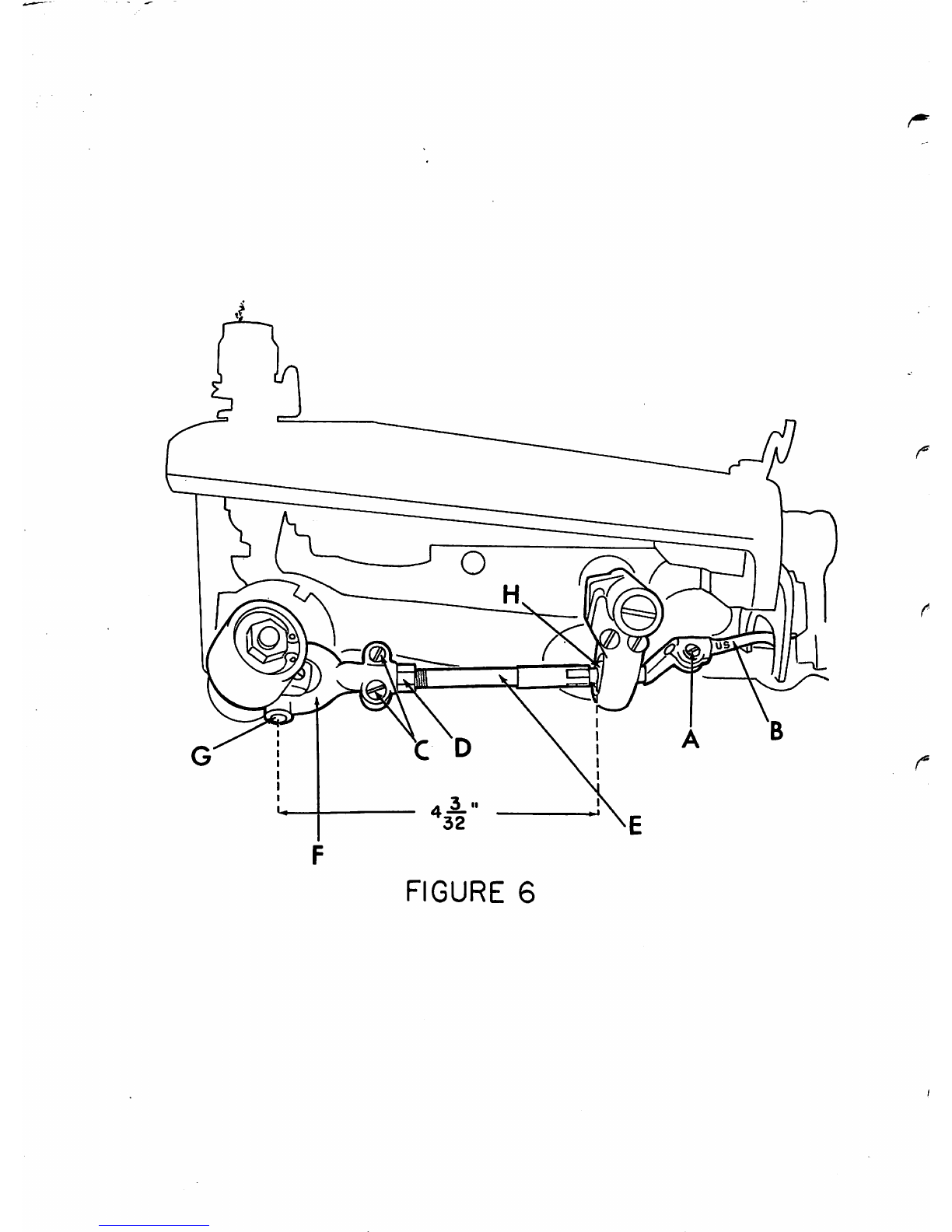
1.
Should
it
become
necessary
to
replace
the
looper
(item
"B"
in
Figure
6),
loosen
the
looper
clamp
screw
(item
"A"
in
Figure
6) and remove
the
old
looper.
Because
of
the
precise
fit
of
the
looper
in
the
looper
rod
it
may
be necessary to
exert
a moderate
amount
of
{
force
to
pull
the
looper
out.
Insert
the
new
looper
into
the
end
of
the
rod
as
far
as
it
will
go
before
bottoming
on
the
looper
shoulder.
r
2.
Any
time a looper
is
moved
or changed, recheck the looper
timing
and
reset
if
necessary. Proper looper timing
is
jJ
absolutely
essential
for
correct
stitch
formation.
As
described
in
detail
below,, a
properly
timed
looper
will
pass over the needle in the correct position to pick
up
the
loop, and
also
clear
the
chain-off
pin,
feeder,
looper
slot,
and
needle.
The
first
check
point for timing
the looper
is
at
the position
where
the looper picks the ^
thread loop
off
the needle during the needle
return
stroke.
u,
Referring
to
Figure 7, (Point "C"), the long prong of the
looper
should
pass
over
and
just
clear the scarf of the |
needle, approximately 3/32"
(2.4mm)
behind the
end
of the
c.
needle eye. At the
same
time, the short prong of the
looper should pass over the needle with about 1/64
(.406mm)
clearance,
and
must
be so
set
that
it
also
clears
the
chain-off
pin
(item
"D"
in
Figure
7).
• 'V>h' I
Si