8. Once clearance is established between the needle and the looper crotch,
continue
turning
the
handwheel away from
the
operator
until
the
needle
passes between the looper prongs, clearing
both
the long and the
short
prong.
If difficulty is experienced at this point, it may be necessary to modify some
of
the previous adjustments to the eccentric block or the looper rod length.
If this is done, recheck
the
previous
points
to insure
that
aposition is estab
lished
which
will satisfy all
of
the
clearance
conditions.
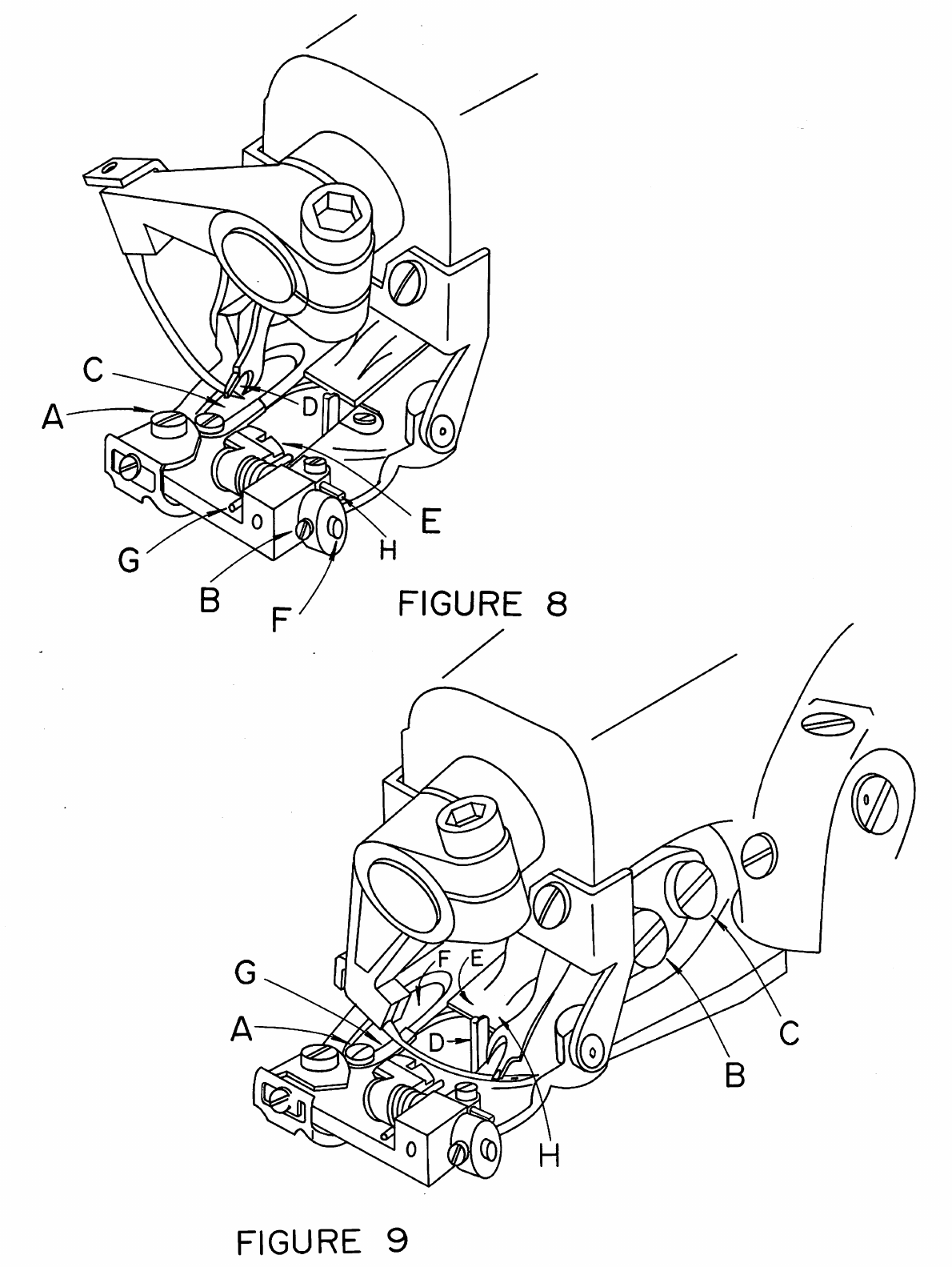
9. After all the necessary adjustments have been made, tighten all set screws and
the lock
nut
and recheck all the adjustment points. Referring to Figure 9, the
looper
should
now
clear
the
chain-offpin
("D"),
feeder
("E"),
looper
slot
("F"),
needle, and pass over the needle in the correct position to pick up the
loop.
B.
REPLACING
THE
NEEDLE
GUIDE
1. After considerable service, it may be expected
that
the wearing action
of
the
needle will cause asharp edged groove to form on
the
needle guide (item
"G"
in
Figure
9).
This condition can cause thread breakage
and
uneven penetration. When this
happens the guide should be replaced. The needle guide was specifically design
ed as a readily replaceable wear
plate
to
prevent damage
to
the
presserfoot from
the
action
of
the
needle.
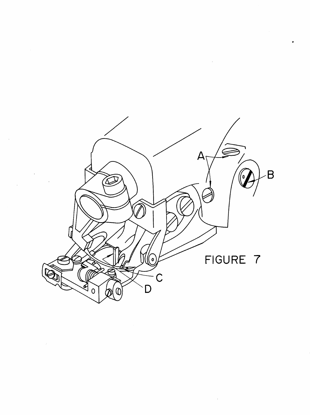
2. Loosen
the
needle guide attaching screw (item
"A"
in Figure 9) and remove the
worn
needle guide. Clear
out
any
lint
or
dirt
that
may
have
accumulated
under
the
old guide and insert
the
new guide. Insure
that
the
new guide is seated flush
with
the
top
and
side
of
the
presserfoot
and
then
retighten
the
attaching screw.
Slowly
turn
the
handwheel in the direction away from
the
operator
and check
to
insure
that
the
new
guide fits
properly
under
the
needle
and
that
no
inter
ference has
been
introduced
between
the
guide
and
the
looper.
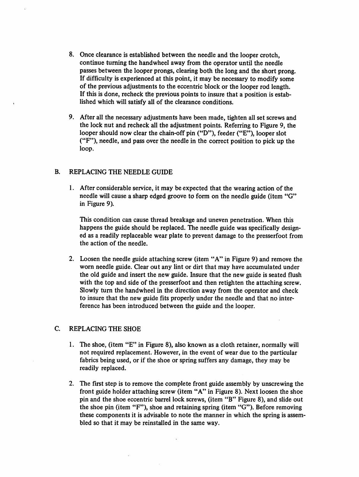
REPLACING
THE
SHOE
1.
The
shoe,
(item
"E"
in Figure
8),
also
known
as a
cloth
retainer,
normally
will
not
required
replacement.
However,
in
the
event
of
wear
due
to
the
particular
fabrics being used,
or
if
the
shoe
or
spring suffers
any
damage,
they
may
be
readily
replaced.
2.
The
first
step
is to remove
the
complete
front
guide assembly by unscrewing
the
front
guide
holder
attaching
screw
(item
"A"
in
Figure
8).
Next
loosen
the
shoe
pin
and
the
shoe
eccentric
barrel
lock
screws,
(item
"B"
Figure 8),
and
slide
out
the
shoe
pin
(item
"F'*),
shoe
and
retaining
spring
(item
"G*').
Before
removing
these
components
it is advisable
to
note
the
manner
in
which
the
spring is assem
bled
so
that
it
may
be reinstalled in
the
same
way.
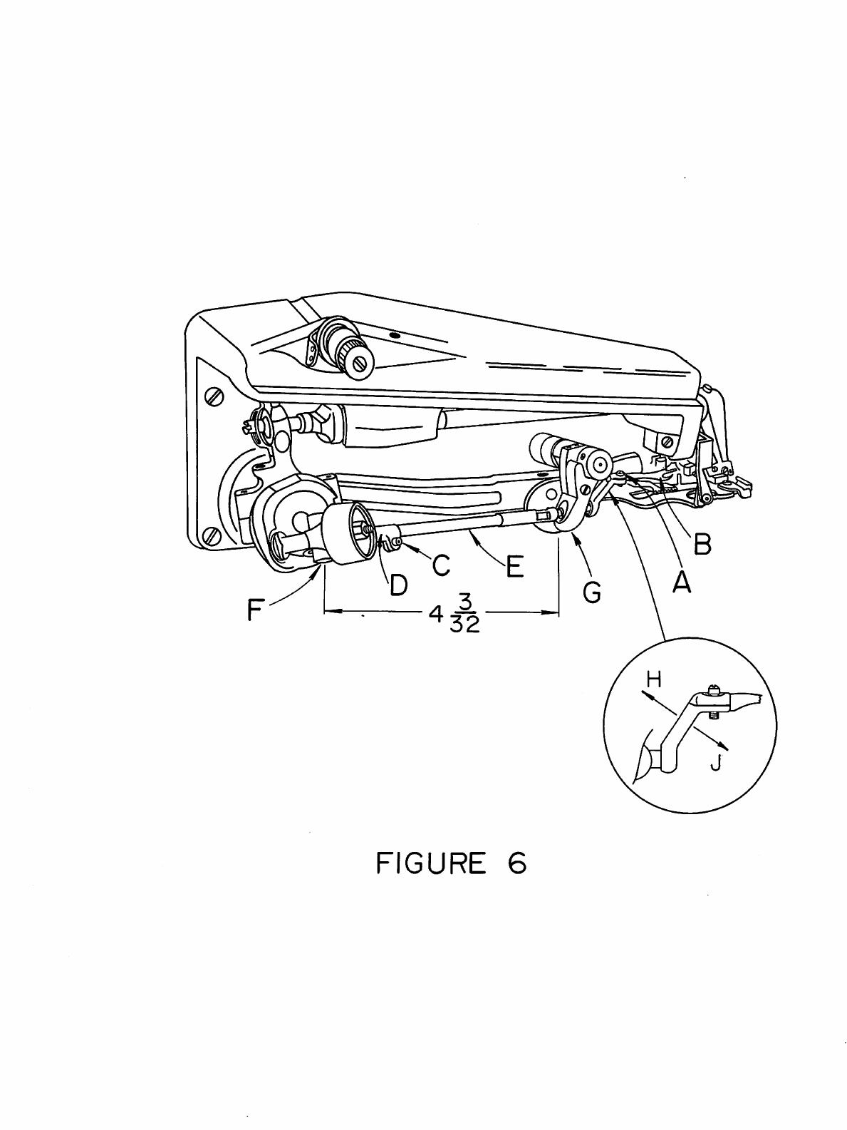
From the library of: Superior Sewing Machine & Supply LLC