JUKI DDL-8700 User manual

ii
ENGLISH

CONTENTS
1. SPECIFICATIONS .................................................................................... 1
2. SET-UP ..................................................................................................... 1
1. Installing the motor unit ......................................................................................... 1
2. Installing the control box ....................................................................................... 1
3. Installing the belt .................................................................................................... 2
4. Adjusting the pulley cover ..................................................................................... 2
5. Installation and adjustment for the protecting pin
and the belt slip-off preventing bracket................................................................ 3
6. Connecting the cords .............................................................................................. 4
7. Attaching the connecting rod ............................................................................... 11
3. FOR THE OPERATOR ........................................................................... 11
1. Operation of SC-500 ............................................................................................. 11
2. Explanation of the operation panel ..................................................................... 13
3. Setting for functions of SC-500 ........................................................................... 18
4. Function setting list .............................................................................................. 20
5. Detailed explanation of selection of functions .................................................. 24
6. Automatic compensation of neutral point of the pedal sensor ........................ 32
7. Bobbin thread remaining amount detection device, AE ................................... 32
8. Connection of the pedal of standing-work machine ......................................... 32
9. Setting of the auto lifter function ........................................................................ 33
10. Connection of the material end sensor (ED) ..................................................... 33
11. Initialization of the setting data .......................................................................... 34
4. MAINTENANCE ...................................................................................... 34
1. Replacing the fuse ................................................................................................ 34
2. Changing procedure between 100V to 120V and 200V to 240V
(Possible only for the voltage changeover type) ............................................... 36
3. Error codes ............................................................................................................ 37

−1 −
Supply voltage Single phase 100 to 120V 3-phase 200 to 240V Single phase 200 to 240V
Frequency 50 Hz / 60 Hz 50 Hz / 60 Hz 50 Hz / 60 Hz
Operating environment Temperature : 0 to 40˚CTemperature : 0 to 40˚CTemperature : 0 to 40˚C
Humidity : 90% or less Humidity : 90% or less Humidity : 90% or less
Input 390VA (LZ-228*: 460VA) 390VA (LZ-228*: 460VA) 390VA (LZ-228*: 460VA)
1. Installing the motor unit
Install the motor unit on the table with the fitting bolt
asm. supplied with the unit as accessories.
At this time, insert the nuts and washers supplied with
the unit as accessories as shown in the figure so that
the motor unit can be securely fixed on the table.
1) Press three bolts 1supplied with the unit as
accessories into the motor hanging bolt hole in the
table and fix them.
2) Temporarily tighten convex washer, spring washer
and nut on the side where two bolts are attached.
3) Hang the motor unit to the washer which has been
temporarily tightened, and attach convex washer,
spring washer and nut to the other bolt on the
opposite side.
4) After adjusting the installing position of the motor,
securely tighten the respective nuts.
2. Installing the control box
1) Loosen four screws 2supplied with the motor unit
as accessories, tighten screws 2after hanging
control box unit 3to the screws, and fix control
box unit 3.
1.SPECIFICATIONS
2.SET-UP
Install the motor unit to the control box following the instructions below.
1
2
3
Spring
washer
Nat
Convex
washer
(Caution) 1. Indication of the power consumption is the mean power consumption when DDL-8700
is mounted in accordance with the operating conditions JUKI specifies.
2. The power consumption changes in accordance with the operating conditions and the
mounted machine head. So, be careful.
3. Instantaneous maximum power consumption may become 1.5 times or more than the
mean power consumption.

−2 −
15mm (9.8N)
a
b
1
1
2
3. Installing the belt
1) The belt distance, between sewing machine pulley
and motor pulley, must be parallel.
2) The belt tension should be adjusted by turning the
tension adjust nuts to change height of the motor,
so that the belt sinks down by about 15 mm (9.8N)
when it is depressed by band at the center of the
belt span.
If the belt tension is not tight, speed is unstable at
low-speed or medium-speed operation, and the
needle will not stop exactly in position.
4. Adjusting the pulley cover
1) After adjusting the belt tension, adjust the pulley
cover 1so that the clearances between the belt
and the pulley cover 1, aand bshould be the
same.
2) After the completion of adjustment, tighten screws
2located on the side of pulley cover 1and
securely fix the pulley cover 1so that it does not
slip out of position.
Tension
adjust nuts
Belt

−3 −
AB
Belt
1
23
4
5
1
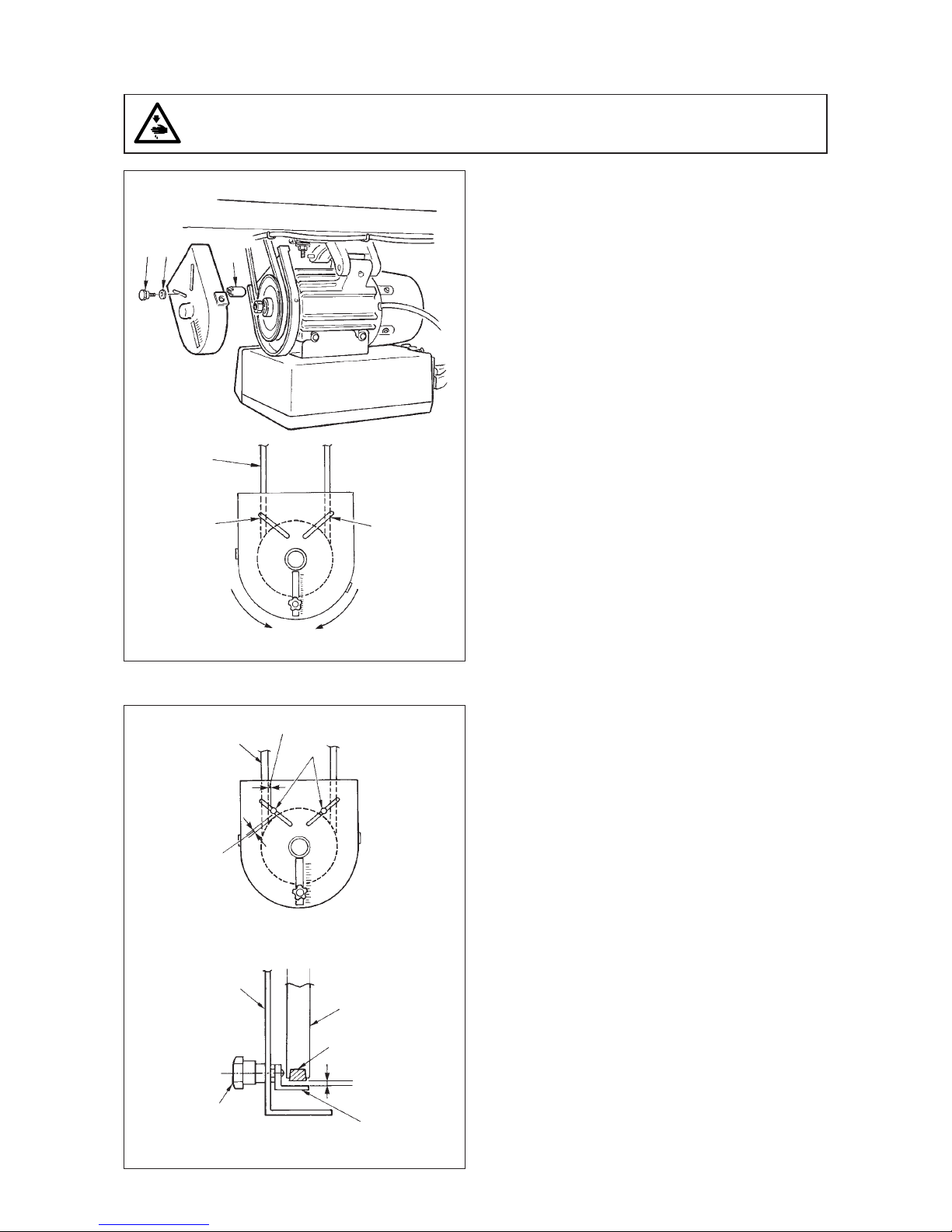
1) Attaching hole for the protecting pin
To attach protecting pin 1, select either attaching
hole Aor attaching hole Bin the motor pulley cover
in accordance with the direction of rotation of the
sewing machine and attach the pin in the selected
hole using screw 2and washer 3supplied with
the unit.
a) If the motor shaft rotates in direction A in the
figure on the above:
/Attach protecting pin 1in attaching hole A.
b) If the motor shaft rotates in direction B in the
figure on the above:
/Attach protecting pin 1in attaching hole B.
2) Adjustment for the protecting pin and the belt slip-
off preventing bracket
Adjust the position of protecting pin 1and belt slip-
off preventing bracket 4in accordance with the
figure on the left.
a) Adjusting the protecting pin
Loosen screw 2and adjust so that protecting
pin 1is positioned at the location indicated in
the figure on the left.
b) Adjusting belt slip-off preventing bracket
Loosen screw 5and adjust so that belt slip-
off preventing bracket 4is positioned at the
location indicated in the figure on the left.
If protecting pin 1is not properly adjusted, it
is possible that your fingers may be caught in
the clearance provided between the pulley and
the belt resulting in injury. If belt slip-off
preventing bracket 4is not properly adjusted,
it is possible to allow the belt to slip off causing
safety hazard.
3) After the adjustment, tighten screws 2and 5so
as to secure protecting pin 1and belt slip-off
preventing bracket 4to prevent these components
to fluctuate because of vibration.
4) Before starting the operation of the sewing
machine, ascertain that protecting pin 1and belt
slip-off preventing bracket 4do not come in contact
with the pulley and the belt.
5. Installation and adjustment for the protecting pin and the belt slip-off preventing bracket
WARNING :
To protect against possible personal injury due to abrupt start of the machine, be sure to start the
following work after turning the power off and ascertaining that the motor is at rest.
4 mm or less
Belt
4 mm or less
Adjusting position for protecting pin
Pulley
cover Motor
pulley
Belt
3 mm or less
Adjusting position for belt slip-off preventing braket
Attaching
hole A
Attaching
hole B

−4 −
Following connectors are prepared when loosening the front cover fixing screws Aof SC-500 and opening the
cover. Connect the machine head connectors to the positions corresponding to each other so as to fit the
devices mounted on the machine head.
WARNING :
•To prevent personal injury caused by abrupt start of the sewing machine, carry out the work after
turning OFF the power switch and a lapse of 5 minutes or more.
•To prevent damage of device caused by maloperation and wrong specifications, be sure to connect
all the corresponding connectors to the specified places.
• To prevent personal injury caused by maloperation, be sure to lock the connector with lock.
•As for the details of handling respective devices, read carefully the Instruction Manuals supplied
with the devices before handling the devices.
6. Connecting the cords
A
9
23
1
45
!0
7
!2
OPC circuit board A (asm.)
!3
A
Front cover
68
!1
!4
!5
!6
1CN30 Motor signal connector
2CN32 Machine head connector
3CN33 Needle bar position detector connector
4CN36 Machine head solenoid connector
5CN37 Presser foot lifter solenoid connector
6CN38 CP-160 panel connector
7CN39 Standing machine pedal connector
8CN40 Signal for extension connector (For the details, refer to Engineer's Manual.)
9CN51 Not used
!0 CN52 Not used
!1 CN53 Bobbin thread remaining amount detection solenoid connector
!2 CN189 External interface signal connector
!3 CN59 Bobbin thread count-up output connector
!4 CN55 Material end detection sensor (ED) connector
!5 CN58 Standing machine pedal connector
!6 CN57 Bobbin thread remaining amount detection sensor connector

−5 −
1) Pass the cords 笊of the thread trimming solenoid,
reverse-stitching solenoid, etc., and the cords of
the synchronizer 笆, machine head 4P connector
3through hole Ain the table to route them down
under the machine table.
2) Loosen setscrew 5in front cover 4.
3) Pressing the side of front cover 4in the direction
of the arrow, open the front cover toward you.
Note : Be sure to open / close the front cover with
your hands.
4) Connect 14P code 1coming from the machine
head to connector 7(CN36).
5) Connect 4P connector coming from the machine
head 3to connector 8(CN32).
6) Connect 7P connector 2coming from the machine
head to connector 9(CN33).
7) When the optional AK device is attached, connect
2P connector coming from the AK device to
connector !1(CN37) .
8) Connect the connector 6coming from the motor
to connector !0 (CN30) on the circuit board.
(Caution)
1. When using the AK device, set whether to
use the AK device after confirming how to
select the auto-lifter function. (Refter to
page 33.)
2. Be sure to securely insert the respective
connectors after checking the inserting
directions since all connectors have the
inserting directions.
(When using a type with lock, insert the
connectors until they go to the lock.)
The sewing machine is not actuated unless
the connectors are inserted properly.
In addition, not only the problem of error
warning or the like occurs, but also the
sewing machine and the control box are
damaged.
3. Perform the insertion of the connector by
lending your hands to the front cover.
1
A23
5
4
1
2
3
6
89
7
!0
!1

−6 −
[ Connection of the connector for CP panel ]
Exclusive connectors are prepared for connection of
the connector for CP-160.
Paying attention to the orientation of the connector
!2, connect it to connector !3 located on the circuit
board. After connecting, securely lock the connector.
9) After inserting the connector, put all cords together
with cable clip band !4 located on the side of the
box.
(Caution)
1. Fix the cord clamp and the cable clip band
following the attaching procedure.
2. When removing the cable clip band,
remove it while pressing the hook of the
cable clip band.
(Caution) 1. Fix the cable clip band following the attaching procedure as shown in the figure.
2. To remove the cable clip band, push the cable clip band until it comes off while pressing
the hook of the band following the removing procedure as shown in the figure.
How to fix cable clip band !4
Pull
How to remove cable clip band
Push
Pushing the hook portion, push the band to remove it.
Push the hook.
Pull Push
!2
!3
!4
Push

−7 −
12)Connect connector 4P !5 to connector !
6locat
ed
on the side of the box.
13)Connect motor
outpu
t cord !7 of the power switch
to connector !8.
14)Binding of the cords coming from machine head
Bind the cable attached to the machine head at
two places with the cable clip band !9 supplied with
the unit as accessories as shown in the figure.
(Do not bind the motor signal cable together.)
15)Make sure that the power switch is turned OFF
and insert power supply cord @0 coming from the
power switch into the power plug socket.
(Caution)
1. Check again the supply voltage indicated
on the control box before connecting the
power cord.
2. Prepare the power switch conformed to the
safety standard.
3. Be sure to connect the ground wire ( green
/ yellow).
5
4
!5
!6
!7
!8
@0
!9
!9
10) Close front cover 4while paying attention to
pinching of the wire.
11) After that, fix it with the screw 5.

−8 −
1
2
3
4
Crimp style terminal section
b
4
5
[ For CE specifications only ]
1) Remove three screws 1located on the side of the
control box.
2) Set power source cover installing plate 2supplied
with the unit as accessories to the control box main
unit with the three screws which have been
removed.
3) Remove nut section 4from cord bush 3supplied
with the unit as accessories.
4) After checking the direction of the nut, pass the
nut through the power source cord supplied with
the unit as accessories.
(Caution) Note that the flat face of the nut should
face the power source cover installing plate
side.
5) Pass the terminal of the power source cord through
the hole from the inside of the power source cover
installing plate.
6) Pass the cord bush, while paying attention to the
direction, through the power source cord from the
power source cord terminal side.
7) Insert connector 5of the power source cord to
the connector (top) of the control box.
(Caution) Securely insert the connector while
paying attention to the direction.
8) Tighten nut 4and securely fix the cord bush to the
installing plate.
9) Clamp section bof the cord bush and securely fix
it to the cord.

−9 −
6
8
7
10) Insert connector 6coming from the motor to the
connector of the control box from the inside.
11) Securely fix power source cover 7supplied with
the unit as accessories to power source cover
installing plate 2with two screws 8supplied with
the unit as accessories while being careful that the
cord is not caught by the cover.
* For handling the cable, refer to 14) and 15) of 6. Connecting the cords.

−10 −
1
2
3
5
4
6
1) Remove three screws 1located on the side of the
control box.
2) Set power source cover installing plate 2supplied
with the unit as accessories to the control box main
unit with the three screws which have been
removed.
3) Pass the terminal of the power source cord through
the hole from the inside of the power source cover
installing plate.
4) After checking the direction of the nut 3, pass the
nut through the power source cord supplied with
the unit as accessories and insert it into the conduit.
(Caution) Note that the flat face of the nut should
face the power source cover installing plate
side.
5) Securely fix it to the installing fittings with nut 3
from both sides.
[ For LA specifications only ]
6) Insert connector 4of the power source cord to the connector (top) of the control box.
(Caution) Securely insert the connector while paying attention to the direction.
7) Securely fix power source cover 5supplied with the unit as accessories to power source cover installing
plate 2with two screws 6supplied with the unit as accessories while being careful that the cord is not
caught by the cover.
* For handling the cable, refer to 14) and 15) of 6. Connecting the cords.

−11 −
3.FOR THE OPERATOR
1. Operation of SC-500
1) Press ON button 笊of the power switch to turn ON
the power.
(Caution) When the buzzer is kept beeping
immediately after turning ON the power,
press OFF button 2on the sewing machine
to turn OFF the power since connection of
the cord or power voltage may be wrong.
2) When the needle bar is not in its UP position, it
automatically rotates to reach the UP position.
(Caution)
1. When turning ON the power for the first
time, it will be slightly delayed since
initialization is performed.
2. When turning ON the power, do not place
your hands under the needle.
3) When depressing front part 4of the pedal, the
sewing machine rotates at the number of
revolutions in accordance with the depressing
amount.
When the pedal is returned to the neutral position,
the sewing machine stops.
4) When lightly depressing back part 5of the pedal,
the presser goes up. (PFL type only)
5) When strongly dpressing back part 6of the pedal,
thread trimming is performed.
(Caution) For KFL and PFL types, thread trimming
entering point is different from each other.
7. Attaching the connecting rod
1) Fix connecting rod 1to installing hole Bof pedal
lever 2with nut 3.
2) Installing connecting rod 1to installing hole Awill
lengthen the pedal depressing stroke, and the pedal
operation at a medium speed will be easier.
WARNING :
To protect against possible personal injury due to abrupt start of the machine, be sure to start the
following work after turning the power off and a lapse of 5 minutes or more.
1
2
B
A
3
笊
笆
5
4
6

−12 −
2
7
8
6) When operation panel 7is connected, various
sewing patterns such as reverse feed stitching at
sewing start, reverse feed stitching at sewing end,
etc. can be set.
Refer to the Instruction Manual for the operation
panel for the details.
7) When pressing touch-back switch 8, reverse feed
can be performed.
8) When sewing is completed, make sure that the
sewing machine has stopped.
Then, press the OFF button 2of the power switch
to turn OFF the power.

−13 −
2. Explanation of the operation panel
1/ switch : Used for determining the contents of setting.
When this switch is pressed, flashing stops and the contents of setting
are determined.
2 / switch : Used for changing the contents of setting.
When this switch is pressed, changeable positions flash on and off.
By pressing the switch, flashing position shifts in the right direction.
3switch : Used for changing the contents of the selected display (flashing
section).When this switch is pressed, the contents of the display
increase.
4switch : Used for changing the contents of the selected display (flashing
section).
When this switch is pressed, the contents of the display decrease.
5PATTERN SELECTION display : The selected pattern is displayed.
6REVERSE STITCHING : Rendered effective when reverse stitching pattern is selected.
AT START display “ ” Without reverse stitching display / “ ” Reverse stitching display/
“ ” Double reverse stitching display
7REVERSE STITCHING : Rendered effective when reverse stitching pattern is selected.
AT END display “ ” Without reverse stitching display / “ ” Reverse stitching display/
“ ” Double reverse stitching display
8NUMBER OF STITCHES display : Number of stitches of reverse stitching or overlapped stitching is
displayed.
9MATERIAL EDGE SENSOR : Lights up when the material edge sensor setting is selected.
display Function setting No. 2
!0 ONE-SHOT AUTOMATIC : Lights up when the one-shot automatic stitching is selected.
STITCHING display Function setting No. 76
!1 AUTOMATIC : Lights up when the automatic thread trimming by depressing the
THREAD TRIMMING display front part of the pedal is selected.
Function setting No. 3
!2 THREAD TRIMMING : Lights up when the thread trimming prohibition is selected.
PROHIBITION display Function setting No. 9
1243!1 !2
6789!0
5

−14 −
3) Press switch 3or switch 4and
select the reverse stitching pattern.
Reverse stitching patterns and displays are as
follows.
: Reverse stitching
: Double reverse stitching
: Without reverse stitching
4) Press / switch 1to make reverse
stitching at end display 7flash on and off, and set
the pattern in the same way as step 3).
[ Setting procedure of the reverse stitching ]
1) Hold pressing / switch 1, and press
/ switch 2to select the reverse
stitching pattern.
(Every time / switch 2is pressed,
reverse stitching pattern/overlapped stitching
pattern change over alternately.)
2) Press / switch 1to make reverse
stitching at start display 6flash on and off.
Every time / switch 1is pressed, the
flashing position shifts in the right direction.
(Caution) The sewing machine does not start in
the flashing state.
Operating procedure of the sewing pattern
(1) Reverse stitching pattern
Reverse stitching patterns below can be set by using the operation panel.
Reverse stitching patterns that can be set
Reverse stitching
at start display
Sewing pattern
A
Overlapped stitching pattern
Reverse stitching pattern
B
D
C
D
C
A
B
A
BB
A
D
C
D
C
A
B
A
B
A
B
D
C
D
C
D
C
D
C
D
C
A
B
A
B
1
21
2
1
Shift direction
Flash
Contents of reverse
stitching slection
updating with swith3
3
4
⇔
7
6
7
6Flash
updating with swith4
1
Reverse stitching
at end display

−15 −
5) Press / switch 1to make number of
stitches display 6flash on and off, and set the
number of stitches for the respective processes of
the stitching.
6) Press switch 3or switch 4to
change the number of stitches.
The number of stitches can be changed up to as
many as 15 stitches for the A, B, C, and D
processes respectively.
However, displays are as follows.
10 stitches = A, 11 stitches = b, 12 stitches = c, 13
stitches = d, 14 stitches =E and 15 stitches = F
7) When the setting of all items has been completed,
press / switch 2to determine the
contents of the setting. (Flashing stops.)
1
243
8
A
B
C
B
C
D
1
21
2
⇔
1
243
6
Overlapped stitching pattern
Reverse stitching pattern
(2) Overlapped stitching pattern
Overlapped stitching patterns below can be set by using the operation panel.
A : Number of stitches of normal stitching setting
0 to 15 stitches
B : Number of stitches of reverse stitching setting
0 to 15 stitches
C : Number of stitches of normal stitching setting
0 to 15 stitches
D : Number of times of repetition
0 to 9 times
(Caution) When process D is set to 5 times, the
sewing is repeated as A /B /C /B /C.
[Setting procedure of the overlapped stitching]
1) Hold pressing / switch1, and press
/ switch 2to select the overlapped stitching
pattern.
(Every time / switch 2is pressed,
reverse stitching pattern/overlapped stitching
pattern change over alternately.)
2) The number of stitches for process A becomes in
flashing state.
3) Every time / switch 1is pressed, the
flashing position shifts in the right direction and the
display of the process where setting can be
changed flashes on and off.
4) Press switch 3or switch 4to
change the number of stitches.
5) When the setting of all processes has been
completed, press / switch 2to
determine the contents of the setting. (Flashing
stops.)
(Caution) When the overlapped stitching is
selected, the automatic operation display
flashes on and off. It is not possible to
release the automatic operation.

−16 −
13
4
a
a
13
13
4
13
4
(3) Special setting
For material end sensor function, automatic thread trimming function, one-shot automatic stitching function and thread
trimming prohibition function which are displayed in the front panel, it is possible to change the set value by directly
moving to the function setting mode while the power is turned ON in addition to the normal function setting procedure.
[ Moving procedure to the function setting mode ]
1) Hold pressing / switch 1, and press
switch 3to move to the function setting
mode.
(Caution) Function setting No. 2 is displayed
immediately after the changeover.
2) When returning to the normal mode, press /
switch 2and determine the contents of
the setting.
1Material end sensor function setting (Function
setting No. 2)
It is rendered effective when connecting the
optional material end sensor.
It is possible to change the set value with
switch 3or switch 4
0 : Material end sensor function is prohibited.
1 : Material end sensor function is effective.
When "1" is selected, material
end sensor display lights up
when the mode has returned to
the normal one.
2Thread trimming operation after material end stop
setting (Function setting No. 3)
Press / switch 1to advance to the
function setting No. 3.
It is possible to change the set value with
switch 3or switch 4.
0 : Material end stop
1 : Automatic thread trimming after detection
of material end
When "1" is selected, the
automatic thread trimming
display lights up when the mode
is returned to the normal one.
3Number of stitches to stop the sewing machine after
detection of material end setting (Function setting
No. 4)
Press / switch 1to advance to the
function setting No. 4.
It is possible to change the set value with
switch 3or switch 4.
Specified number of stitches : 0 to 19 stitches
2

−17 −
a
a
13
4
13
4
4One-shot automatic stitching setting function
(Function setting No. 76)
Press / switch 1to advance to the
function setting No. 76.
It is possible to change the set value with
switch 3or switch 4.
0 : Pedal designated speed is prior.
1 : Automatic operation
(Caution) It is rendered effective when the material
end sensor function is set.
It is not possible to prohibit the one-shot
operation at the time of the overlapped
stitching operation.
Speed of rotation is the speed set at the
function setting No. 38.
When "1" is selected, the one-
shot automatic stitching display
lights up when the mode is
returned to the normal one.
5Thread trimming prohibition function setting
(Function setting No. 9)
Thread trimming operation at normal stitching and
overlapped stitching can be prohibited by selecting
the thread trimming prohibition.
Press / switch 1to advance to the
function setting No. 9.
It is possible to change the set value with
switch 3or switch 4.
0 : Thread trimming is effective.
1 : Thread trimming is prohibited.
When "1" is selected, the thread
trimming prohibition display lights
up when the mode is returned to
the normal one.
(Caution) When the specified number of stitches
is insufficient, there is a case where the
sewing machine cannot stop within the
specified number of stitches depending on
the speed of rotation of the sewing
machine.

−18 −
3. Setting for functions of SC-500
Functions can be selected and specified by means of the four setting switches and light emitting diode located
inside the front cover of the SC-500.
(Caution) • Do not perform switch operations other than those described in the following explanations.
•Be sure to re-turn the power switch ON after one second or more has passed. If the power
is turned ON immediately after turning it OFF, the sewing machine may not work normally.
In this case, turn ON the power again.
How to change over to the function setting modo
1) Turn OFF the power to the unit.
2) Pressing switch 4, turn ON the power to the unit.
3) Indication 5,6 will be shown on the display. (If
the indication fails to change, re-perform the
procedures 1) and 2).
1234
5
6
4
4
1Switch for entering specified value changed
and updating setting No. in DOWN direction
2Switch for entering specified value changed
and updating setting No. in UP direction
Specified value
Specified No.
3Down switch (DOWN)
4Up switch (UP)
Other manuals for DDL-8700
3
This manual suits for next models
1
Table of contents
Other JUKI Sewing Machine manuals

JUKI
JUKI M-1 Series User manual

JUKI
JUKI TL-98QE User manual

JUKI
JUKI DMN-530-4 User manual

JUKI
JUKI DU-141H-4 User manual

JUKI
JUKI MO-103N User manual

JUKI
JUKI DLM-5400N-7 User manual

JUKI
JUKI DLU-5494N-7 User manual

JUKI
JUKI LU-2810-7 Series User manual

JUKI
JUKI AK118 User manual

JUKI
JUKI DU-1181 Quick start guide

JUKI
JUKI MO-6000G Series Quick start guide

JUKI
JUKI HZL-70HW-B User manual

JUKI
JUKI HZL-12Z User manual

JUKI
JUKI TL-2010Q User manual

JUKI
JUKI DDL-8700-7 User manual

JUKI
JUKI TSU-471 Quick start guide

JUKI
JUKI LBH-1795AN User manual

JUKI
JUKI DLN-6390 Quick start guide

JUKI
JUKI LZ-271 User manual

JUKI
JUKI LBH-781 User manual