U.S. BLIND STITCH 1099 Series Instruction Manual

U.S.
BLIND
STITCH
MACHINE
COHP.
EXPRESS
STREET
&
SKYLINE
DRIVE
PLAINVIEW
N.Y.
11803
TELEPHONE:
516-433-4350
CABLE
ADDRESS:"BLINSTIT
PLAINVIEW
NEW
YORK"
1099
SERIES
COVERING
THE
FOLLOWING
STANDARD
SUB
CLASSES:
1099LP
1099LP-1
1099PB
1099PB-1
1099PBT
1099PBW
MAINTENANCE
<&
PARTS
CATALOG
©
1979
•
U.S.
BLIND
STITCH
MACHINE
CORF.
U
S,
r-';
Mi
I
m
From the library of: Diamond Needle Corp

ni
-
MAINTENANCE
INSTRUCTIONS
FOR
1118,1099
&
1108
SERIES
INTRODUCTION
A. Replacing
the
Looper
B. Replacing
the
Needle Guide
C. Replacing
the
Shoe
D. Replacing
the
Feeder
From the library of: Diamond Needle Corp

MAINTENANCE
INSTRUCTIONS
INTRODUCTION
All U.S. BLIND STITCH machines are designed for long life and trouble-free performance. When
installed
and
lubricated
in
accordance
with
the
INSTALLATION
AND
OPERATING
INSTRUC
TIONS, only the minimum maintenance normally associated with industrial sewing machines will
be required. These maintenance requirements will generally be
confined
to
the
four
locations des
cribed
below,
at
which
wear
may
be
expected
after
extended
use. When
such
wear
does
occur,
the
worn
part
may
be readily
replaced
by
following
the
appropriate
instructions.
For
ease
of
installa
tion, and to insure satisfactory service, it is essential
that
only genuine U.S. BLIND STITCH parts
and needles are used. They are
the
only
parts designed specifically
for
the
machine, with
the
built-
in long life
and
excellent wearing characteristics typical
of
the
U. S. BLIND STITCH machine.
A.
REPLACING
THE
LOOPER
1. Should it become necessary to replace the looper (item
"B"
in Figure 6),
loosen
the
looper
clamp
screw
(item
"A"
in Figure 6)
and
remove
the
old
looper. Because
of
the
precise fit
of
the looper in
the
looper
rod
it may be
necessary
to
exert
a
moderate
amount
of
force
to
pull
the
looper
out.
Insert
the new looper
into
the end
of
the
rod as far as it will go before
bottoming
on
the
looper
shoulder.
2. Any time a looper is moved or changed, recheck the looper timing and reset
if
necessary.
Proper
looper
timing is absolutely essential
for
correct
stitch
formation. As described in detail below, aproperly timed
looper
will pass
over
the
needle in
the
correct
position
to
pick
up
the
loop,
and
also clear
the
chain-off pin, feeder, looper slot, and needle. The first check
point
for timing
the
looper
is at the position where the looper picks
the
thread loop
off
the
needle during the needle return stroke. Referring to Figure 7, (Point
"C"),
the
long
prong
of
the
looper
should
pass over
and
just
clear
the
scarf
of
the
needle, approximately
3/32"
(2.4mm)
behind
the
end
of
the
needle eye. At
the
same time,
the
short
prong
of
the
looper
should
pass over
the
needle
with
about
1/64"
(.406mm)
clearance,
and
must
be so
set
that
it also clears
the
chain-off
pin
(item
"D"
in Figure 7).
From the library of: Diamond Needle Corp

3. To adjust the looper so that the timing checks out as noted in paragraph 2,
it may be rotated within its clamp by a limited amount. This adjustment
should be made with the looper clamp screw (item
"A"
in Figure 6) loosened,
and the looper bottomed against its shoulder. Do
not
move the looper in or
out, and do
not
attempt
to force the looper
to
turn beyond the limited
amount
of
travel
available.
4.
If
the adjustment described in paragraph 3 is insufficient to provide
the
correct
timing, it willbe necessary to turn the looper rod (item
"E"
in Figure6) itself.
Thismay be accomplishedby looseningwith looper rod clamp screw (item
"C"
in Figure6). The rod is then free to turn in the looper rod fork (item
"D"
in
Figure 6). It will normally be necessary to make only a very small adjustment
in order to get the looper into the correct rotational position for proper timing.
If, for any reason,
the
rod has been removed
or
the
basic setting
of
the
looper
rod
has
been
disturbed
by
alarge
amount,
it
may
be
reset
by
noting
that
the
distance from
the
center
of
the
looper
rod
fork
pin (item
"F"
in Figure 6)
to
the rear face of the looper rod ball (item
"G"
in Figure 6) is normally 4 & 3/32
inches (104mm) (refer to Figure 6). If the rod is set to this dimension then only
minor
adjustment
will be required
to
bring
the
looper
into
the
correct
timing
position. Note
that
this dimension is merely a guide
to
assist in setting a rod and
variations
may
be
expected
from
machine
to
machine.
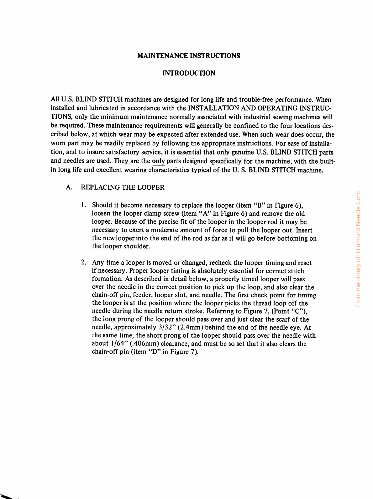
5. If, after completing the above adjustments, it is found
that
the looper is either
too
low or
too
high, it will be necessary
to
adjust
the
eccentric stud. First loosen
the
two
set
screws (item
"A"
in Figure 7). Place a wide blade screwdriver in
the
slot
of
the
eccentric
stud
(item
"B"
in Figure 7) and, using a slight turning
motion,
raise or lower the
looper
as required. Once
the
proper
height is established, check
to see whether the looper must be moved to the left or
to
the right prior to retight-
ening the eccentric block set screws. If such a movement is required, it may be ob
tained by lightly tapping the eccentric block in the correct direction with the
handle
of
a
screwdriver.
From the library of: Diamond Needle Corp

0
0\
FIGURE
6
From the library of: Diamond Needle Corp

6. Once the looper is timed with respect to the needle as outlined in paragraphs 2
thru
5above, slowly
turn
the
handwheel in a direction away from
the
operator,
until the looper approaches the edge
of
the looper slot. (Point
"C"
in Figure 8)
in the presserfoot. At this point make sure the small prong
of
the looper clears
this edge. If it does
not
clear, adjust the eccentric block as outlined in paragraph
5
until
the
interference
is
eliminated.
6A. If timing
of
looper still proves difficult, its possible
that
looper sweep required
adjustment. If looper is too close to chain
off
pin and also, too close to needle
guide on opposite position,
the
looper
sweep is
too
short.
If looper on pick up stroke, is
too
far to right
of
chain
off
pin and
too
close
to
needle
rest
at
left
of
presserfoot,
the
looper
sweep is
too
wide.
For
adjustment, refer
to
insert illustration (Figure 6). To widen
looper
sweep,
flex or bend looper crank in direction
of
arrow
"H".
To shorten looper.sweep,flex or bend looper crank in direction
of
arrow
"J".
Both
adjustments should be gradual and sweep checked frequently.
7. Continue turning
the
handwheel away from
the
operator
until
the
point
of
the
needle starts to
enter
the area in between the looper prongs. (Refer to Point
"D"
in Figure 8). If the needle strikes the crotch
of
the looper, the looper has general
ly been set too far forward. Check to see if the looper has been inserted into the
clamp as far as it will go. It should be inserted until
the
shoulder on the looper
is stopped on the clamp. If this check is satisfactory, recheck the distance from
the center
of
the looper rod fork pin to the rear face
of
the looper rod ball. Refer
to
paragraph 4 and reset
if
necessary. If
neither
of
the
above
two
measures
cor
rects
the
problem, it is possible
that
the needle lever
may
be set
too
low and
required
adjustm.ent.
From the library of: Diamond Needle Corp

FIGURE
7
From the library of: Diamond Needle Corp

8. Once clearance is established between the needle and the looper crotch,
continue
turning
the
handwheel away from
the
operator
until
the
needle
passes between the
looper
prongs, clearing
both
the long and the
short
prong.
If
difficulty is experienced at this
point,
it
may
be necessary to modify some
of
the
previous adjustments to
the
eccentric block or the
looper
rod
length.
If
this is
done,
recheck
the
previous
points
to
insure
that
aposition is estab
lished
which
will satisfy all
of
the
clearance
conditions.
9. After all the necessary adjustments have been made, tighten all set screws and
the
lock
nut
and
recheck all
the
adjustment
points. Referring to Figure 9, the
looper
should
now
clear
the
chain-off
pin
("D"),
feeder
("E"),
looper
slot
("F"),
needle,
and
pass over
the
needle in
the
correct position to pick up
the
loop.
B.
REPLACING
THE
NEEDLE
GUIDE
1.
After
considerable
service,
it
may
be
expected
that
the
wearing
action
of
the
needle will cause asharp edged groove
to
form
on
the
needle guide
(item
"G"
in
Figure
9).
This
condition
can
cause
thread
breakage
and
uneven
penetration.
When
this
happens
the
guide
should
be replaced.
The
needle guide was specifically design
ed as a readily
replaceable
wear
plate
to
prevent
damage
to
the
presserfoot
from
the
action
of
the
needle.
2. Loosen
the
needle guide
attaching
screw (item
"A"
in Figure
9)
and
remove
the
worn
needle guide. Clear
out
any
lint
or
dirt
that
may
have
accumulated
under
the
old guide
and
insert
the
new guide. Insure
that
the
new
guide is seated flush
with
the
top
and
side
of
the
presserfoot
and
then
retighten
the
attaching
screw.
Slowly
turn
the
handwheel in
the
direction away from
the
operator
and
check
to
insure
that
the
new guide fits
properly
under
the
needle
and
that
no
inter
ference
has
been
introduced
between
the
guide
and
the
looper.
C.
REPLACING
THE
SHOE
1.
The
shoe, (item
"E"
in Figure 8), also known as a
cloth
retainer, normally will
not
required
replacement.
However,
in
the
event
of
wear
due
to
the
particular
fabrics being
used,
or
if
the
shoe
or
spring suffers
any
damage,
they
may
be
readily
replaced.
2. The first
step
is
to
remove
the
complete
front
guide assembly by unscrewing
the
front
guide
holder
attaching screw (item
"A"
in Figure 8). Next loosen
the
shoe
pin and the shoe eccentric barrel lock screws, (item
"B"
Figure 8), and slide
out
the
shoe
pin
(item
"F"),
shoe
and
retaining spring (item
"G")-
Before removing
these
components
it is advisable
to
note
the
manner
in which the spring is assem
bled
so
that
it
may
be
reinstalled in
the
same
way.
From the library of: Diamond Needle Corp

e
FIGURE
8
FIGURE
9
From the library of: Diamond Needle Corp

3.
When
replacing
an
old
shoe,
make
sure
that
the
replacement
shoe
properly
fits
the
pin
without
binding
and
without
excessive looseness. In
the
event
that
the
pin
has
worn
and
does
not
fit
the
new
shoe
properly,
it
should
be
replaced
at
the
same
time
as
the
shoe-pin.
After
replacing
the
shoe,
shoe
pin
spring
into
shoe
eccentric
barrel,
re-
tighten
screws
(item
"B"
Figure 8),
and
check
to
insure
that
the
center
of
the
shoe
is
lined
up
with
the
center
of
the
rib. Also insure
that
the
shoe
clears
both
sides
of
the
opening
of
the
presserfoot.
4. In
and
out
position
of
shoe should
now
be checked.
For
light fabrics, shoe should
be as close
to
needle as possible.
For
heavy fabrics
with
seam,
shoe
should
be
set
back
as far as possible from needle. To move
shoe
in
and
out
turn
eccentric barrel
(item
"I"
Figure 8). After the correct location is established, be sure to tighten
screws,
(item
"B"
Figure
8).
4A. An additional shoe
adjustment
is also possible.
The
height
of
the shoe can now be
controlled, (item *'H" in Figure 8). This is a tapered pin
and
position can be ad
justed so
that
the shoe, whenever required, can be controlled as far as elevation is
concerned. By moving the tapered pin in or
out
the shoe can be kept from pressing
down on some fabrics which require little, if any shoe pressure. By having this
control, it sometimes will aid in penetration
of
difficult fabrics. The normal posi
tion
of
the shoe, when set properly on most fabrics, is
that
the shoe will show move
ment
on
the
penetration
cycle on
one
ply
of
fabric.
5.
REPLACING
THE
CHAIN
OFF
PIN
1. After considerable service, it may become necessary to replace
the
chain
off
pin,
(Item
"D"
in Figure 7).
2. Remove the chain off pin attaching screwand remove the chain off pin, clean
out any lint or dirt that may
have
accumulated. Attach the newchainoff pin,
using
the
screw
previously
removed.
Insure
that the
chain
off pinis
against
the
side and forward edge of the slot in the presserfoot, and then tighten the screw.
From the library of: Diamond Needle Corp

D.
REPLACING
THE
FEEDER
1. In
the
event
that
the
machine develops difficulty by failing to properly feed
the
work,
a
worn
feeder is
frequently
found
to
be
the
cause.
After
considerable service,
especially with certain hard fabrics,
the
feeder
teeth
have a tendency to become
dull,
and
the
feeder
should
be
replaced.
In
order
to
remove
the
old
feeder,
remove
the
front
feeder
attaching
screw
(item
"B"
in Figure
9)
and
loosen
the
rear
feeder
attaching
screw
(item
"C"
in Figure
9).
The
old
feeder
may
then
be slid
out
of
place.
Insert
the
new
feeder
under
the
rear
screw
and
replace
the
front
screw.
2. Before
tightening
the
attaching
screws
check
to
see
that
the
feeder is
set
to
the
proper
depth.
Referring
to
Figure 10 this should be
approximately
1/32"
(.795mm)
below
and
parallel
to
the
bottom
of
the
presserfoot
for
all
light
and
medium
weight
fabrics.
For
heavy fabrics,
the
setting
should be
approximately
1/16"
(1.59mm)
below
and
parallel
to
the
bottom
of
the
presserfoot.
These
dimensions
are
intended
as
guides
and
may
be
modified
as
required
by
the
specific
fabrics.
Once
the
proper
depth
is
established,
rotate
the
hand
wheel
slowly
in a
direction
away
from
the
oper
ator
and
check
to
insure
that
the
feeder
clears
the
looper
(see Figure 9,
Point
"H")
and
also
clears
both
sides
of
the
feeder
slot
in
the
presserfoot.
Firmly
tighten
feeder
attaching screws (Figure 9, Items
"B"
&
"C")
before resuming sewing.
0
FIGURE
10
From the library of: Diamond Needle Corp

1099
SERIES
PARTS
CATALOGUE
COVERING
THE
FOLLOWING
STANDARD
SUB-CLASSES:
1099LP
1099LP-1
1099PB
1099PB-1
1099PBT
1099PBW
MAIN
FRAME
GROUP
5182
Side
Cover
Assembly
1005
1401
Washer,
Clamp
Screw
1006
5019
Screw,
Side
Cover
1093
7004
Guard,
Belt
1289
1069
Screw,
Guard
1240
5174
Thread
Tension
Regulating
Ass'y.
1089
Consists
of:
7028
7023
Thread
Guide
1096
1324
Disc."
Thread
Tension
1107
1330
Post,
Thread
Tension
3281
1329
Spring,
Tension
1108
7022
Nut,
Tension
1080
1811
Pin,
Spring
1070
3021
Screw,
Feed
Lever
Plate
Tube,
Oil
Wick,
Oil
Screw,
Set
Screw,
Set
Pin,
Presserfoot
Screw,
Set
Plate,
Top
Cover
Screw,
Top
Cover
Screw,
Bridge
Mtg.
Washer,
Clamp
Screw
Screw,
Clamp
Thread
Guide
Screw,
Thread
Guide
From the library of: Diamond Needle Corp

ASS
Y
I
070
I
080
005
7022
I
324
I
089
I
240^
^
I I
08
50
19
MAIN
FRAME
GROUP
I
330
5 I
74
I
006
I
096
I
006
I
069
7004
From the library of: Diamond Needle Corp

7012
5003-1*
5004-1*
See
Table
5041-1*
See
Table
MAIN
SHAFT
GROUP
Main
Shaft
1845
Rib
Connection
Lever
&
Eccentric
Ass'y,
1974
Screw
Eccentric
5226**
1973
Screw
For
Stud
1880
Screw,
Clamp
Needle
Connection
Ass*y.
1072
Screw
1134-1
Guard
1132
Screw
5231
1131-1
Screw
Needle
Connection
Ass'y.
1072
Screw
1134-1
Guard
1132
Screw
1131-1
Screw
*Sold
as
an
Assembly
Only
**
The
Following
Optional
Handwheel
Ass'y.
Are
Available
5188-1
Handwheel
With
Position
Hub
5240
Handwheel
Double
Pulley
Ass'y.
5253
Handwheel,
Double
Pulley
and
Positioner
Hub
Ass'y.
TABLE
Collar
Ass'y.
1971
Screw
Handwheel
Ass'y.
3290
Handwheel
3291
Screw
3032
Pulley
Ass'y.
1121
Screw
1069
Screw
Stitch
Collar
Ass'y.,
Regular
1834
Set
Screw
Model
Needle
Connection
Ass'y
1099PB,
1099PB-1,
1099PBT
1099LP,
1099LP-1,
1099PBW
5041-1
5004-1
From the library of: Diamond Needle Corp

(2)
I
072
(2)
I I
32
>SEE
TABLE
331
(2)1072
(2)1 8
34
7012
1973
1015
ASS'Y
ASSY
5228
ASS'Y
SEE
FEED
DRIVE
GROUP
2 I
974
5003-1
ASS'Y
I
880
2
197!
5175
ASS'Y
MAIN
SHAFT
GROUP
3032
!
ASS'yJ
5226-
ASS'Y
From the library of: Diamond Needle Corp

FEED
DRIVE
GROUP
5208
Feed
Lever
&
Stitch
Collar
Ass'y
(Sold
as
Ass'y.
only)
5016
Feed
Rocker
Ass'y.
3019
Feed
Lever
Plate
3021
Screw
-
Lever
Plate
1821
Thrust
Collar
Ass'y
1870
Set
Screw
2100*
Feeder
1119
Feeder
Screw
*Types
of
Feeders
Available
Fine
2101
Armoloyd
2125
Carbide
2119
Rubber
2120
From the library of: Diamond Needle Corp

50
I 6
ASS'Y
2
00
2 I I
19
FEED
DRIVE
GROUP
5208
ASS'Y~1
2
1834
ASS'Y
ASST
I
82
ASS
Y
(2
18
70
30
I 9
From the library of: Diamond Needle Corp

5082
NEEDLE
DRIVE
GROUP
Needle
Lever
Ass*y
1076
3050
1137
1243
1136
Screw
Screw
Clamp
Pin
Lever
5135
Collar
Ass'y.
1089
Screw
1095
Shaft
1118
Screw
NEEDLE
SIZES
AVAILABLE
Use
Genuine
U.S.B.S,
Needles
for
Best
Results
Long
Needles
-
System
251
Regular
Point
Sizes
00
10
15
20
25
30
35
40
55
Ball
Point
Sizes
10
15
20
25
Spear
Point
Sizes
10
15
20
25
30
35
65
Short
Needles*
*Short
Needles
Used
on
Model
LP,
LP-1
0
1
1
2
2
3
3
4
4
1/2
1/2
1/2
1/2
From the library of: Diamond Needle Corp

37
5082
J
'243
ASS'Y^
II
36
il076
I I I 8
(2)1
089
3050
NEEDLE-SPECIFY
SIZE
REQUIRED
NEEDLE
DRIVE
GROUP
From the library of: Diamond Needle Corp

Part
No,
2200
1150
5233
5230
5213
5186
5206
LOOPER
DRIVE
GROUP
Description
Looper
Stud,
Looper
Adjustment
Collar
Ass'y.
1870
Set
Screw
Looper
Rod
Fork,
Sleeve
&
Stud
Ass'y
Consists
of:
1154
Fork
1155
Pin
3049
Screw
1979
Nut
1123
Stud
1146
Nut
5006
Looper
Rod
Sleeve
Ass'y.
(Not
sold
separately)
1094
Screw
Looper
Rod
&
Fork
Ass'y.
Consists
of:
51^5
Looper
Rod
&
Ball
Ass'y.
1154
Fork
3049
Screw
1979
Nut
Looper
Rod
&
Carrier
Ass'y.
Consists
of:
5017
Looper
Rod
Carrier
Ass'y.
1117
Screw
5185
Looper
Rod
&
Ball
Ass'y.
Looper
Rod,
Fork
&
Carrier
Ass'y.
Consists
of:
5186
Ass'y.
1154
Fork
3049
Screw
1979
Nut
From the library of: Diamond Needle Corp
Other manuals for 1099 Series
2
This manual suits for next models
6
Table of contents
Other U.S. BLIND STITCH Sewing Machine manuals

U.S. BLIND STITCH
U.S. BLIND STITCH 718-1 User manual

U.S. BLIND STITCH
U.S. BLIND STITCH 1118 Series User manual

U.S. BLIND STITCH
U.S. BLIND STITCH 1099 Series Instruction Manual

U.S. BLIND STITCH
U.S. BLIND STITCH 1118 Series Instruction Manual

U.S. BLIND STITCH
U.S. BLIND STITCH 1099 Series Instruction Manual