U.S. BLIND STITCH 1118 Series User manual

UU.S. BLINDSTITCH
MACHINE COMPANY
IS A DIVISION OF NEWYORK SEWING MACHINE ATTACHMENT CORP.
Stitching Perfection
2011-15 85th Street, North Bergen, NJ 07047
Tel: 201-809-2009 • 1-800-225-2852 • FAX: 201-861-9201
e-mail: sewingmachines@usblindstitch.com • www.usblindstitch.com
SERIES: 1118, 1099, 718, 99
STANDARD SUBCLASSES
MAINTENANCE CATALOG
COPYRIGHT © 2001 U.S. BLINDSTITCH MACHINE COMPANY IS A DIVISION OF NEW YORK SEWING MACHINE ATTACHMENT CORP. ALL RIGHTS RESERVED.
THIS CATALOG AND/OR ANY PORTION THEREOF MAY NOT BE REPRODUCED IN ANY FORM WHATSOEVER WITHOUT WRITTEN PERMISSION OF ITS COPYRIGHT OWNER.
INSTALLATION
AND OPERATING
INSTRUCTIONS
FOR
U.S. BLINDSTITCH
MACHINES
From the library of: Diamond Needle Corp

U.S. BLINDSTITCH MACHINE CO.
IS A DIVISION OF NEWYORK SEWING MACHINE ATTACHMENT CORP.
2011-15 85th Street, North Bergen, NJ 07047 •Web: www.usblindstitch.com
Tel: 201-809-2009 • 1-800-225-2852 • FAX: 201-861-9201 • e-mail: [email protected]
2
A Machine is Only as Good as its NEEDLE!
Don’t Take Chance – Avoid Trouble
Top quality sewing demands top quality machines equipped with top quali-
ty needles to achieve perfect results.
Peak efficiency in today’s high-speed sewing of synthetics, and wash and
wear fabrics is accomplished only with needles of superior quality and perform-
ance.
Imitations or substitutes are a costly compromise. Pennies saved on infe-
rior needles only prove to be expensive dollars in the long run.
The quality of U.S. Needles is, in fact, a matter of world-wide recognition
and cannot be duplicated. The confidence of our customers in U.S. Needles is
the knowledge that quality is always and has been foremost in our products.
For durability and freedom from breakage, U.S. Needles are unequalled.
Their uniform construction, carefully controlled finish and curvature assure
efficient, economical stitching.
BE SURE TO USE ONLY
GENUINE U.S. NEEDLES
Look for this Label
on all parts
The same precision construction and working
perfection exists in all U.S. Machine Parts.
BE SURE TO GET U.S. – ACCEPT NO SUBSTITUTE
GENUINE
U.S. NEEDLES
U.S. BLINDSTITCH
MACHINE CO.
2011-15 85th Street
North Bergen, NJ 07047
1-800-225-2852
TEL: 201-809-2009
FAX: 201-861-9201
From the library of: Diamond Needle Corp

U.S. BLIND STITCH MACHINE CO.
IS A DIVISION OF NEWYORK SEWING MACHINE ATTACHMENT CORP.
2011-15 85th Street, North Bergen, NJ 07047 •Web: www.usblindstitch.com
Tel: 201-809-2009 • 1-800-225-2852 • FAX: 201-861-9201 • e-mail: [email protected]
3
INDEX
Adjusting The Depth Of Needle Penetration . . . . . . . . . . . . . . . . . . . . . 8
Adjusting The Knee Lifter. . . . . . . . . . . . . . . . . . . . . . . . . . . . . . . . . . . . 6
Adjusting The Length Of Stitch. . . . . . . . . . . . . . . . . . . . . . . . . . . . . . . 10
Adjusting The Stitch Line Location . . . . . . . . . . . . . . . . . . . . . . . . . . . . . 8
Adjusting The Thread Tension . . . . . . . . . . . . . . . . . . . . . . . . . . . . . . . . 8
Inserting The Work In The Machine . . . . . . . . . . . . . . . . . . . . . . . . . . . . 8
Installation And Operating Instructions . . . . . . . . . . . . . . . . . . . . . 3 thru 6
Lubricating The Machine . . . . . . . . . . . . . . . . . . . . . . . . . . . . . . . . . . . . 7
Maintenance Instructions for 1118, 1099 & 1108 Series . . . . . . 12 thru 17
Needles . . . . . . . . . . . . . . . . . . . . . . . . . . . . . . . . . . . . . . . . . . . . . . . 11
Replacing the Feeder. . . . . . . . . . . . . . . . . . . . . . . . . . . . . . . . . . . . . . 15
Replacing the Looper. . . . . . . . . . . . . . . . . . . . . . . . . . . . . . . . . . 12 & 13
Replacing the Needle. . . . . . . . . . . . . . . . . . . . . . . . . . . . . . . . . . . . . . 15
Replacing the Needle Guide. . . . . . . . . . . . . . . . . . . . . . . . . . . . . . . . . 15
Threading the Machine . . . . . . . . . . . . . . . . . . . . . . . . . . . . . . . . . . . . . 6
Threading the Shoe . . . . . . . . . . . . . . . . . . . . . . . . . . . . . . . . . . . . . . 15
❖❖❖
INSTALLATION AND OPERATING INSTRUCTIONS
I. UNPACKING AND INSTALLING THE MACHINE
A. Unpacking
B. Fitting the machine to the table top
C. Locating the machine with respect to the table edge
D. Motor drive
II. OPERATING INSTRUCTIONS
A. Lubricating the machine
B. Adjusting the knee lifter
C. Threading the machine
D. Inserting the work in the machine
E. Adjusting the stitch line location
F. Adjusting the thread tension
G. Adjusting the depth of needle penetration
H. Adjusting the length of stitch
I. Replacing the needle
From the library of: Diamond Needle Corp

U.S. BLINDSTITCH MACHINE CO.
IS A DIVISION OF NEWYORK SEWING MACHINE ATTACHMENT CORP.
2011-15 85th Street, North Bergen, NJ 07047 •Web: www.usblindstitch.com
Tel: 201-809-2009 • 1-800-225-2852 • FAX: 201-861-9201 • e-mail: [email protected]
4
INSTALLATION AND OPERATING INSTRUCTIONS
I. UNPACKING AND INSTALLING THE MACHINE
A. UNPACKING
1. Cardboard Carton: Open the carton and remove the corrugated liner. Insure that the envelope
containing the accessories is not misplaced or accidentally discarded. Lift the machine out of the
carton with the plywood base still attached. Next, remove the bolts attaching the plywood base,
and set the bolts aside for use in mounting the machine.
B. FITTING THE MACHINE TO THE TABLE TOP
1. The machine should be mounted on a blank table top, if possible.
C. LOCATING THE MACHINE WITH RESPECT TO THE TABLE EDGE
1. The specific location will depend upon the style and model of the machine being mounted.
a. Models without work plates, such as the 1099-PB-1 etc., are set even with the front edge
of the table top.
b. Models with regular size work plates (swing-away or stationary), such as the 1118-1108
etc., are set with the work plate extended one inch (1”) to one and one half inches (1”)
beyond the front edge of the table top.
c. Models with extra-large work plates are set back far enough from the front edge of the
table top to permit mounting of the support post. The edge of the support post should be set
back about one inch (1”) from the forward edge of the table top.
d. These locations may be varied somewhat to suit the comfort of the operator and the
nature of the particular type of work to be handled. In all cases it is extremely important to
insure that the lifter rod will clear the edge of the table.
2. After establishing the position of the machine as noted above, move it sideways until the
machine handwheel lines up with the motor drive pulley. The belt slot may now be cut in the
table top. Install the belt to insure that the correct machine location has been established. Mark
the center of the bolt holes in the base of the machine, and remove,the machine from the table
top. Drill 3/8" holes for the mounting bolts, place the felt pad, supplied with each machine, on
the table top, replace the machine in its proper location and install the attaching bolts, washers
and nuts. Insure that the machine is firmly clamped in position and the bolts securely fastened.
3. Position the thread stand behind the machine to the right of the handwheel, and secure in
place with the supplied wood screws.
D. MOTOR DRIVE
1. The machine is shipped with a handwheel and pulley combination which is properly sized to
insure operation at the correct speed when used in accordance with the following recommendations.
a. When an individual motor and clutch unit is employed, it is recommended that the motor
be rated at 1/3 HP and 1725/1750 RPM. On all standard models, a 3” pulley should be used.
On models intended for alteration work such as the 1118-2, a 2” pulley should be used.
b. When the machine is mounted on a power table stand, a 4” pulley should be employed.
If at all possible, when using such stands, the machine should be so mounted so as to avoid
twisting the belt.
c. The maximum machine speed recommended for any installation is 3000 RPM, unless
otherwise specified.
2. The machine should be mounted so as to insure that the direction of rotation of the handwheel
is away from the operator. In other words, the handwheel rotates in a clock-wise direction when
looking at the face of the wheel pulley, as shown by the arrow in Figure 1.
3. Either V-belting or round leather belting may be used. When installing the belt use Just
enough tension to prevent slippage. Excessive tension will cause rapid belt wear and can possibly
damage the machine.
From the library of: Diamond Needle Corp

U.S. BLIND STITCH MACHINE CO.
IS A DIVISION OF NEWYORK SEWING MACHINE ATTACHMENT CORP.
2011-15 85th Street, North Bergen, NJ 07047 •Web: www.usblindstitch.com
Tel: 201-809-2009 • 1-800-225-2852 • FAX: 201-861-9201 • e-mail: [email protected]
5
CAUTION: BEFORE OPERATING THE MACHINE LUBRICATE IN ACCORDANCE
WITH THE INSTRUCTIONS IN THE FOLLOWING SECTION.
II. OPERATING INSTRUCTIONS
A. LUBRICATING THE MACHINE
1. Before operating the machine, it is extremely important that it be properly lubricated in accordance
with the following instructions. The use of GOOD QUALITY MACHINE OIL is recommended,
do not use stainless oils or motor oil.
2. Place a few drops of oil at all the points shown on the oiling chart in Figure 1. Remove the
side cover shown on Figure 1 by loosening the cover attaching bolt “A”. Then place a few drops
of oil at all the points shown on-the oiling chart in Figure 2.
3. In production use, the machine should be oiled on a daily basis in accordance with the
instructions in item 2 above.
FIGURE 1
OIL
OIL
DIRECTION OF
HANDWHEEL
ROTATION
OIL
OIL
OIL
SIDE COVER
From the library of: Diamond Needle Corp

U.S. BLINDSTITCH MACHINE CO.
IS A DIVISION OF NEWYORK SEWING MACHINE ATTACHMENT CORP.
2011-15 85th Street, North Bergen, NJ 07047 •Web: www.usblindstitch.com
Tel: 201-809-2009 • 1-800-225-2852 • FAX: 201-861-9201 • e-mail: [email protected]
6
4. For special purpose machines DP MODEL equipped with two main bearing gravity feed oil
cups, it is necessary to insure that sufficient oil is maintained in the visible reservoir. The addition
of oil is readily accomplished through the conveniently located filler hole on top of the reservoir.
When the toggle on top of these oil cups is in the upright position, a metered amount of oil is
continuously delivered from the reservoir to the bearing. If the machine is to be left idle for any
period of time, the toggle should be flicked to the horizontal position in order to shut off the oil
flow. It is important to note that machines equipped with these gravity feed oil cups must also
be lubricated in accordance with the instructions in item 2 above, except for the two locations
where the oilers are found.
5. The electric motor drives should be lubricated in accordance with the motor manufacturer’s
recommendations.
B. ADJUSTING THE KNEE LIFTER
1. In order to insure optimum operator comfort, the knee lifter has been provided with 2 adjustments.
a. The lifter pad may be moved up and down the lifter rod by loosening the set screw on the
back of the pad, moving it to the proper knee height, and retightening the set screw.
b. The lifter rod itself may be moved from left to right as follows: Loosen the screw attaching
the small window plate on top of the feed frame (see Figure 1, item “B”) and swing this
plate out of the way. By inserting a screw driver into the window, the two screws which lock
the lifter rod to the lifter rod bracket may be loosened. Move the rod to the desired location
and tighten the two lifter rod bracket screws. Replace the window plate in its proper location
and tighten the window plate screws.
C. THREADING THE MACHINE
1. Use any type of thread which is suitable for the work being sewn. This includes mercerized,
silk and synthetic threads.
2. Prior to starting the threading operation, the handwheel should be turned in the direction
away from the operator until the needle reaches the extreme left hand portion of its swing. This
will put it into the most convenient position for threading.
FIGURE 2
OIL
OIL
OIL
OIL
OIL
OIL
From the library of: Diamond Needle Corp

U.S. BLIND STITCH MACHINE CO.
IS A DIVISION OF NEWYORK SEWING MACHINE ATTACHMENT CORP.
2011-15 85th Street, North Bergen, NJ 07047 •Web: www.usblindstitch.com
Tel: 201-809-2009 • 1-800-225-2852 • FAX: 201-861-9201 • e-mail: [email protected]
7
3. Referring to the threading chart in Figure 3, it can be seen that the threading procedure is a
simple one. The thread is passed from front to back through the rear thread guide hole “A”. It
then slides between the two tension discs “B” and is brought out to the right of the guide arm
“C”. Carried forward, the thread is passed through the front thread guide “D” and down through
the needle clamp guide hole “E”. It then is passed through the eye of the needle "F", entering
on the underside of the needle and being removed at the top. The thread should be pulled
through to extend past the eye of the needle by a few inches.
D. INSERTING THE WORK IN THE MACHINE
1. Prior to inserting the work, the handwheel should be turned in the direction away from the operator
until the needle reaches the extreme left hand portion of its swing.
2. The knee lifter is then pressed to the right which drops the feed frame and creates a gap
between the presser foot and the platters.
3. The work is inserted underneath the presser foot and the edge of the hem fold or the ribbon
edge is lined up with the center of the spring-loaded cloth retainer or “shoe”. The lifter is then
released which locks the work in position. It is very important to insure that during machine operation,
the operator’s knee is not permitted to rest against the knee lifter. This can effect needle penetration
and result in non-uniform stitch quality.
FIGURE 3
SIDE VIEW
From the library of: Diamond Needle Corp

U.S. BLINDSTITCH MACHINE CO.
IS A DIVISION OF NEWYORK SEWING MACHINE ATTACHMENT CORP.
2011-15 85th Street, North Bergen, NJ 07047 •Web: www.usblindstitch.com
Tel: 201-809-2009 • 1-800-225-2852 • FAX: 201-861-9201 • e-mail: [email protected]
8
4. Atrial run should now be made along a few inches of work. Do not attempt to pull the work
through the machine as the machine will feed it automatically at the proper rate. The operator
merely needs to guide the work by resting it against the edge guide located on the presser foot.
E. ADJUSTING THE STITCH LINE LOCATION
1. If, on the trial run, it is found that the stitch formation has missed the edge of the hem fold or ribbon,
the edge guide, which is located at the front of the presser foot, should be moved to the left.
2. If it is found that the stitch formation is too far past the edge of the hem fold or ribbon, the edge
guide should be moved to the right.
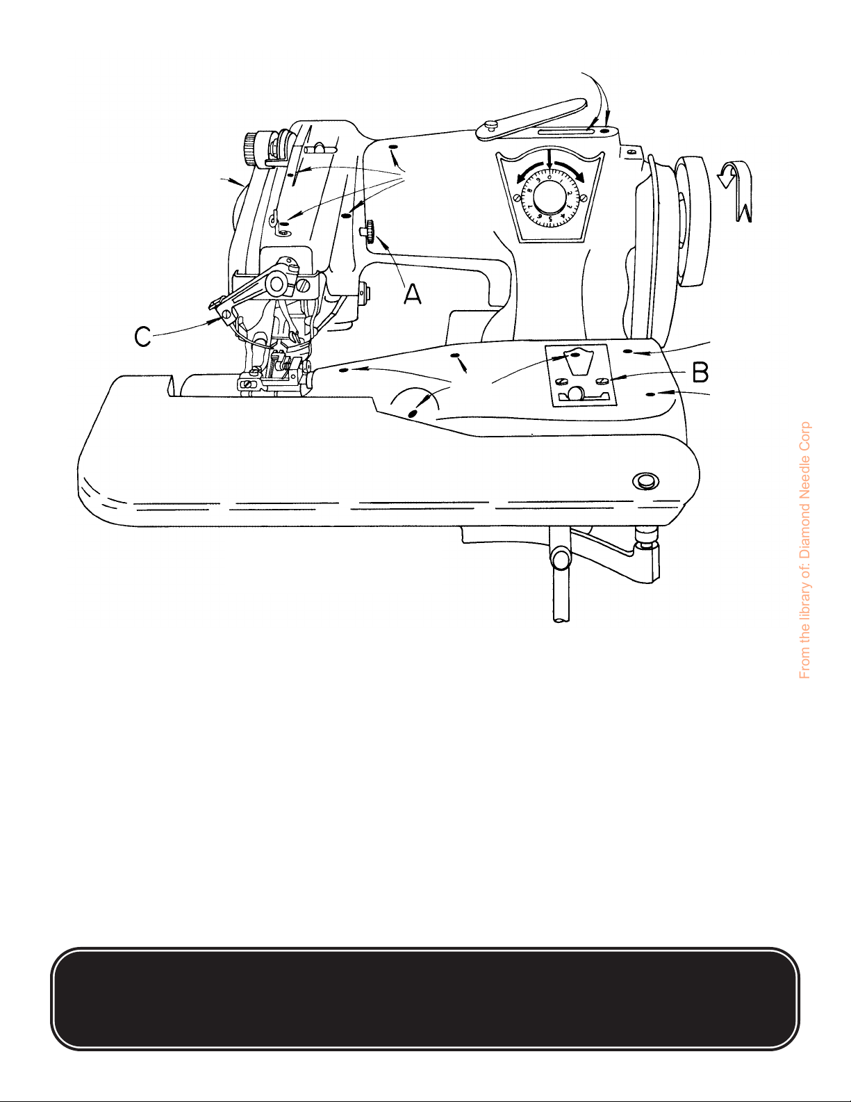
F. ADJUSTING THE THREAD TENSION
1. Insufficient thread tension will result in a loose, poorly holding stitch. If the trial run indicates this
to be the case, turn the tension nut (item“G”in Figure 3) to the right, thus increasing thread tension.
2. Too much thread tension may result in puckering of the work, thread breakage, and skipped
loops. If this happens, turn the tension nut to the left, loosening the thread tension.
G. ADJUSTING THE DEPTH OF NEEDLE PENETRATION
1. Because of the large variation in the thickness and nature of the fabrics encountered in
production operations, U.S. BLIND STITCH machines incorporate a simple and convenient device
to compensate for these variations. The exact degree of needle penetration desired is obtained by
merely turning the penetration dial conveniently located on the front of the machine as shown in
Figure 4.
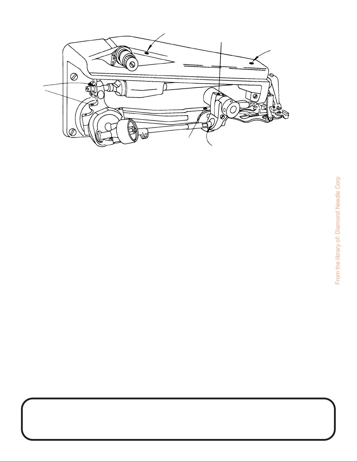
2. The amount of needle penetration of the work which is obtained is governed by the gap between
he needle and the oscillating rib which feeds the work into the needle. This is illustrated by the two
views at the bottom of Figure 4. The view at the left shows a minimum gap which would be used
with thinner fabrics, and the view at the right shows a large gap which would be employed with the
heavier fabrics. Extremely fine adjustments between these two extremes is readily obtainable.
3. Every machine shipped from the factory has been carefully sewn-off and the needle penetration
adjusted exactly for the fabric used during the sew-off operation. When different fabrics are
employed in the actual production operation it will, of course, be necessary to readjust the penetration
as follows:
a. If the needle skips material or a generally deeper and stronger penetration is desired, turn
the knob on the regulating dial (See Figure 4) a few clicks to the left in the direction of the arrow
indicating “More”. This will raise the rib closer to the needle and provide more penetration. This
adjustment should be made gradually, moving only a few clicks at a time, until exactly the correct
amount of penetration is obtained.
b. If too deep a penetration is obtained, turn the knob on the regulating dial (See Figure 4) a
few clicks to the right in the direction of the arrow indicating “Less”. This will lower the rib and provide
less penetration.
c. If the machine has been maintained in the proper adjustment, it should never be necessary
to move too far in either the “More” or “Less” direction in order to obtain the proper penetration. If
a change in excess of four or five numbers on the dial is required without achieving the proper
penetration, the needle should be carefully inspected. A blunted or feathered needle will not provide
the proper penetration. If a good needle is installed and it still does not catch the material, it is likely
that the knob has been turned one or more full revolutions out of adjustment. If for this or any other
reason it becomes necessary to reset the penetration dial to the correct position, the following
procedure should be used.
From the library of: Diamond Needle Corp

U.S. BLIND STITCH MACHINE CO.
IS A DIVISION OF NEWYORK SEWING MACHINE ATTACHMENT CORP.
2011-15 85th Street, North Bergen, NJ 07047 •Web: www.usblindstitch.com
Tel: 201-809-2009 • 1-800-225-2852 • FAX: 201-861-9201 • e-mail: [email protected]
9
FIGURE 4
RIB SHAFT
ADJUSTMENT
FOR – MORE – RIB SHAFT
ADJUSTMENT
FOR – LESS –
PENETRATION DIAL
From the library of: Diamond Needle Corp

U.S. BLINDSTITCH MACHINE CO.
IS A DIVISION OF NEWYORK SEWING MACHINE ATTACHMENT CORP.
2011-15 85th Street, North Bergen, NJ 07047 •Web: www.usblindstitch.com
Tel: 201-809-2009 • 1-800-225-2852 • FAX: 201-861-9201 • e-mail: [email protected]
10
1. On skip-stitch models place the skip-stitch ratio lever in the 1 to 1 position.
2. Turn the handwheel in the proper direction until the point of the needle is directly over the center
(or high point) of the rib.
3. Turn the knob to the left “More” until the rib just barely touches the point of the needle.
4. Make another test run and adjust the knob in accordance with (a) and (b) above.
H. ADJUSTING THE LENGTH OF STITCH
1. It is rarely necessary to change the length of the stitch on U.S. BLIND STITCH machines once
they have been preset at the factory. However, in the event that the need does arise, the simple
procedure outlined below should be followed:
2. Remove the side cover by loosening the attaching screw (item “A” in Figure 1) and observe the
machine from the rear.
3. The numbered disc (item“A”in Figure 5) is called the stitch regulating collar. The position of this
collar with respect to a notch on the rim of the feed eccentric (item“B”in Figure 5) determines the
length of stitch. Before changing the length of the stitch, note the original setting of the notch with
respect to the stitch regulating collar.
4. Loosen the screw (item“C”in Figure 5) which locks the stitch regulating collar in position. Insert
a screwdriver blade in the split on the stitch regulating collar which will be found directly beneath
the locking screw. While holding the screwdriver firmly in position, move the handwheel until the
notch on the rim of the feed eccentric is lined up with the desired number on the stitch regulating
collar. To increase the length of stitch from the original setting, move the notch to a higher number.
To decrease the length of stitch from the original setting, move the notch to a lower number.
5. Before retightening the stitch regulating collar locking screw, turn the handwheel slowly by hand
and observe to insure that no interference has been created between the feed dog and the presser
foot and looper.
6. After the correct adjustment has been established, the stitch regulating collar locking screw
should be retightened. When retightening the screw, however, pull the handwheel to the right and
hold it in that position until the screw is completely tight. This will assist in the proper reseating of
the stitch regulating collar.
FIGURE 5
A
B
C
D
From the library of: Diamond Needle Corp

U.S. BLIND STITCH MACHINE CO.
IS A DIVISION OF NEWYORK SEWING MACHINE ATTACHMENT CORP.
2011-15 85th Street, North Bergen, NJ 07047 •Web: www.usblindstitch.com
Tel: 201-809-2009 • 1-800-225-2852 • FAX: 201-861-9201 • e-mail: [email protected]
11
7. After completing the adjustment, thoroughly oil the feed lever and eccentric, particularly in the
area indicated by “D” in Figure 5; and replace the side cover.
I. REPLACING THE NEEDLE
1. U.S. needles are designed and manufactured specifically to meet the precise sewing requirements
of the U.S. BLIND STITCH MACHINES. Because of the importance of a properly designed needle
in achieving consistent high quality stitching, it is extremely important that only GENUINE U.S.
NEEDLES be used at all times.
2. When it becomes necessary to replace worn or damaged needles, the following procedure
should be followed:
a. Turn the penetration dial to the right (“Less”) three or four numbers to insure that the rib is
lowered sufficiently to clear the needle.
b. Loosen the needle clamp screw (item “C” in Figure 1), slide the clamp rearward sufficiently
to release the old needle, and remove and discard it. Insert the new needle and push it up into the
groove of the needle lever as far as it will go. Make sure that the flat on the shank of the needle
faces rearward and the needle is properly seated in the groove. Tighten the needle clamp screw
and turn the handwheel slowly making sure that the needle passes lightly over the needle guide on
the presser foot and clears the looper. Readjust the needle penetration as described in a previous
section, prior to resuming operation.
3. When it becomes necessary to replace worn or damaged needles, the following procedure
should be followed:
a. Turn the penetration dial to the right (“Less”) three or four numbers to insure that the rib is
lowered sufficiently to clear the needle.
b. Loosen the needle clamp screw (item “C” in Figure 1), slide the clamp rearward sufficiently
to release the old needle, and remove and discard it. Insert the new needle and push it up into the
groove of the needle lever as far as it will go. Make sure that the flat on the shank of the needle
faces rearward and the needle is properly seated in the groove. Tighten the needle clamp screw
and turn the handwheel slowly making sure that the needle passes lightly over the needle guide on
the presser foot and clears the looper. Re-adjust the needle penetration as described in a previous
section, prior to resuming operation.
4. NEEDLES NEEDLE SIZES AVAILABLE
Use Genuine U.S. BLIND STITCH Needles for Best Results
Long Needles – System 251
Regular Point Sizes Ball Point Sizes Spear Point Sizes
00 10 10
10 15 15
15 20 20
20 25 25
25 30
30 35
35 65
40
55
Short Needles Also Available – Ask For List
From the library of: Diamond Needle Corp

U.S. BLINDSTITCH MACHINE CO.
IS A DIVISION OF NEWYORK SEWING MACHINE ATTACHMENT CORP.
2011-15 85th Street, North Bergen, NJ 07047 •Web: www.usblindstitch.com
Tel: 201-809-2009 • 1-800-225-2852 • FAX: 201-861-9201 • e-mail: [email protected]
12
III. – MAINTENANCE INSTRUCTIONS FOR 1118, 1099 & 1108 SERIES
INTRODUCTION
A. Replacing the Looper
B. Replacing the Needle Guide
C. Replacing the Shoe
D. Replacing the Feeder
MAINTENANCE INSTRUCTIONS
INTRODUCTION
All U.S. BLIND STITCH machines are designed for long life and trouble-free performance. When
installed and lubricated in accordance with the INSTALLATIONAND OPERATING INSTRUCTIONS, only
the minimum maintenance normally associated with industrial sewing machines will be required. These
maintenance requirements will generally be confined to the four locations described below, at which wear
may be expected after extended use. When such wear does occur, the worn part may be readily replaced
by following the appropriate instructions. For ease of installation, and to insure satisfactory service, it is
essential that only genuine U.S. BLIND STITCH parts and needles are used. They are the only parts
designed specifically for the machine, with the built-in long life and excellent wearing characteristics
typical of the U. S. BLIND STITCH machine.
A. REPLACING THE LOOPER
1. Should it become necessary to replace the looper (item “B” in Figure 6), loosen the looper
clamp screw (item “A” in Figure 6) and remove the old looper. Because of the precise fit of the
looper in the looper rod it may be necessary to exert a moderate amount of force to pull the looper
out. Insert the new looper into the end of the rod as far as it will go before bottoming on the looper
shoulder.
3
__
32
4
FIGURE 6
From the library of: Diamond Needle Corp

U.S. BLIND STITCH MACHINE CO.
IS A DIVISION OF NEWYORK SEWING MACHINE ATTACHMENT CORP.
2011-15 85th Street, North Bergen, NJ 07047 •Web: www.usblindstitch.com
Tel: 201-809-2009 • 1-800-225-2852 • FAX: 201-861-9201 • e-mail: [email protected]
13
2. Any time a looper is moved or changed, recheck the looper timing and reset if necessary.
Proper looper timing is absolutely essential for correct stitch formation. As described in detail
below,a properly timed looper will pass over the needle in the correct position to pick up the loop,
and also clear the chain-off pin, feeder, looper slot, and needle. The first check point for timing
the looper is at the position where the looper picks the thread loop off the needle during the needle
return stroke. Referring to Figure 7, (Point“C”), the long prong of the looper should pass over
and just clear the scarf of the needle, approximately 3/32” (2.4mm) behind the end of the needle
eye. At the same time, the short prong of the looper should pass over the needle with about
1/64” (.406mm) clearance, and must be set that it also clears the chain-off pin (item“D”in Figure 7).
3. To adjust the looper so that the timing checks out as noted in paragraph 2, it may be rotated
within its clamp by a limited amount. This adjustment should be made with the looper clamp
screw (item “A” in Figure 6) loosened, and the looper bottomed against its shoulder. Do not
move the looper in or out, and do not attempt to force the looper to turn beyond the limited
amount of travel available.
4. If the adjustment described in paragraph 3 is insufficient to provide the correct timing, it will
be necessary to turn the looper rod (item “E” in Figure 6) itself. This may be accomplished by
loosening with looper rod clamp screw (item “C” in Figure 6).The rod is then free to turn in
the looper rod fork (item “D” in Figure 6). It will normally be necessary to make only a very
small adjustment in order to get the looper into the correct rotational positirm for proper timing.
If, for any reason, the rod has been removed or the basic setting of the looper rod has been disturbed
by a large amount, it may be reset by noting that the distance from the center of the looper rod
fork pin (item “F” in Figure 6) to the rear face of the looper rod ball (item “G” in Figure 6) is
normally 4 & 3/32 inches (104mm) (refer to Figure 6). If the rod is set to this dimension then
only minor adjustment will be required to bring the looper into the correct timing position. Note
that this dimension is merely a guide to assist in setting a rod and variations may be expected
from machine to machine.
5. If, after completing the above adjustments, it is found that the looper is either too low or too
high, it will be necessary to adjust the eccentric stud. First loosen the two set screws (item“A”
in Figure 7). Place a wide blade screwdriver in the slot of the eccentric stud (item “B” in Figure 7)
and, using a slight turning motion, raise or lower the looper as required. Once the proper height
is established, check to see whether the looper must be moved to the left or to the right prior to
retightening the eccentric block set screws. If such a movement is required, it may be obtained
by lightly tapping the eccentric block in the correct direction with the handle of a screwdriver.
FIGURE 7
From the library of: Diamond Needle Corp

U.S. BLINDSTITCH MACHINE CO.
IS A DIVISION OF NEWYORK SEWING MACHINE ATTACHMENT CORP.
2011-15 85th Street, North Bergen, NJ 07047 •Web: www.usblindstitch.com
Tel: 201-809-2009 • 1-800-225-2852 • FAX: 201-861-9201 • e-mail: [email protected]
14
6. Once the looper is timed with respect to the needle as outlined in paragraphs 2 thru 5 above,
slowly turn the handwheel in a direction away from the operator, until the looper approaches the
edge of the looper slot. (Point “C” in Figure 8) in the presserfoot. At this point make sure the
small prong of the looper clears this edge. If it does not clear, adjust the eccentric block as outlined
in paragraph S until the interference is eliminated.
6A. If timing of looper still proves difficult, its possible that looper sweep required adjustment.
If looper is too close to chain off pin and also, too close to needle guide on opposite position,
the looper sweep is too short.
If looper on pick up stroke, is too far to right of chain off pin and too close to needle rest at left
of presserfoot, the looper sweep is too wide.
For adjustment, refer to insert illustration (Figure 6). To widen looper sweep,
flex or bend looper crank in direction of arrow “H”.
To shorten loopersweep, flex or bend looper crank in direction of arrow “J”
Both adjustments should be gradual and sweep checked frequently.
7. Continue turning the handwheel away from the operator until the point of the needle starts
to enter the area in between the looper prongs. (Refer to Point "D" in Figure 8). If the needle
strikes the crotch of the looper, the looper has generally been set too far forward. Check to see
if the looper has been inserted into the clamp as far as it will go. It should be inserted until the
shoulder on the looper is stopped on the clamp. If this check is satisfactory, recheck the distance
from the center of the looper rod fork pin to the rear face of the looper rod ball. Refer to paragraph
4 and reset if necessary. If neither of the above two measures corrects the problem, it is possible
that the needle lever may be set too low and required adjustment.
8. Once clearance is established between the needle and the looper crotch, continue turning
the handwheel away from the operator until the needle passes between the looper prongs,
clearing both the long and the short prong. If difficulty is experienced at this point, it may be
necessary to modify some of the previous adjustments to the eccentric block or the looper rod
length. If this is done, recheck the previous points to insure that a position is established which
will satisfy all of the clearance conditions.
FIGURE 8
From the library of: Diamond Needle Corp

U.S. BLIND STITCH MACHINE CO.
IS A DIVISION OF NEWYORK SEWING MACHINE ATTACHMENT CORP.
2011-15 85th Street, North Bergen, NJ 07047 •Web: www.usblindstitch.com
Tel: 201-809-2009 • 1-800-225-2852 • FAX: 201-861-9201 • e-mail: [email protected]
15
9. After all the necessary adjustments have been made, tighten all set screws and the lock nut
and recheck all the adjustment points. Referring to Figure 9, the looper should now clear the
chain-off pin (“D”), feeder (“E”), looper slot (“F”), needle, and pass over the needle in the correct
position to pick up the loop.
B. REPLACING THE NEEDLE GUIDE
1. After considerable service, it may be expected that the wearing action of the needle will
cause a sharp edged groove to form on the needle guide (item “G” in Figure 9).
This condition can cause thread breakage and uneven penetration. When this happens the
guide should be replaced. The needle guide was specifically designed as a readily replaceable
wear plate to prevent damage to the presser foot from the action of the needle.
2. Loosen the needle guide attaching screw (item “A” in Figure 9) and remove the worn needle
guide. Clear out any lint or dirt that may have accumulated under the old guide and insert the
new guide. Insure that the new guide is seated flush with the top and side of the presser foot
and then retighten the attaching screw. Slowly turn the handwheel in the direction away from
the operator and check to insure that the new guide fits properly under the needle and that no
interference has been introduced between the guide and the looper.
C. REPLACING THE SHOE
1. The shoe, (item "E" in Figure 8), also known as a cloth retainer, normally will not required
replacement. However, in the event of wear due to the particular fabrics being used, or if the
shoe or spring suffers any damage, they may be readily replaced.
2. The first step is to remove the complete front guide assembly by unscrewing the front guide
holder attaching screw (item “A”in Figure 8). Next loosen the shoe pin and the shoe eccentric
barrel lock screws, (item “B” Figure 8), and slide out the shoe pin (item “F”), shoe and retaining
spring (item “G”). Before removing these components it is advisable to note the manner in
which the spring is assembled so that it may be reinstalled in the same way.
FIGURE 9
From the library of: Diamond Needle Corp

U.S. BLINDSTITCH MACHINE CO.
IS A DIVISION OF NEWYORK SEWING MACHINE ATTACHMENT CORP.
2011-15 85th Street, North Bergen, NJ 07047 •Web: www.usblindstitch.com
Tel: 201-809-2009 • 1-800-225-2852 • FAX: 201-861-9201 • e-mail: [email protected]
16
3. When replacing an old shoe, make sure that the replacement shoe properly fits the pin without
binding and without excessive looseness. In the event that the pin has worn and does not fit the
new shoe properly, it should be replaced at the same time as the shoe-pin. After replacing the
shoe, shoe pin spring into shoe eccentric barrel, retighten screws (item “B” Figure 8), and
check to insure that the center of the shoe is lined up with the center of the rib. Also insure that
the shoe clears both sides of the opening of the presser foot.
4. In and out position of shoe should now be checked. For light fabrics, shoe should be as close
to needle as possible. For heavy fabrics with seam, shoe should be set back as far as possible
from needle. To move shoe in and out turn eccentric barrel (item“I” Figure 8). After the correct
location is established, be sure to tighten screws, (item “B” Figure 8).
4A. An additional shoe adjustment is also possible. The height of the shoe can now be controlled,
(item “H” in Figure 8). This is a tapered pin and position can be adjusted so that the shoe,
whenever required, can be controlled as far as elevation is concerned. By moving the tapered
pin in or out the shoe can be kept from pressing down on some fabrics which require little, if any
shoe pressure. By having this control, it sometimes will aid in penetration of difficult fabrics. The
normal position of the shoe, when set properly on most fabrics, is that the shoe will show movement
on the penetration cycle on one ply of fabric.
D. REPLACING THE CHAIN OFF PIN
1. After considerable service, it may become necessary to replace the chain off pin,
(Item “D” in Figure 7).
2. Remove the chain off pin attaching screw and remove the chain off pin, clean out any lint or
dirt that may have accumulated. Attach the new chain off pin, using the screw previously
removed. Insure that the chain off pin is against the side and forward edge of the slot in the
presser foot, and then tighten the screw.
From the library of: Diamond Needle Corp

E. REPLACING THE FEEDER
1. In the event that the machine develops difficulty by failing to properly feed the work, a worn feeder
is frequently found to be the cause. After considerable service, especially with certain hard fabrics,
the feeder teeth have a tendency to become dull, and the feeder should be replaced. In order to
remove the old feeder, remove the front feeder attaching screw (item “B” in Figure 9) and loosen
the rear feeder attaching screw (item“C”in Figure 9). The old feeder may then be slid out of place.
Insert the new feeder under the rear screw and replace the front screw.
2. Before tightening the attaching screws check to see that the feeder is set to the proper depth.
Referring to Figure 10 this should be approximately 1/32” (.795m below and parallel to the bottom
of the presserfoot for all light and medium weight fabrics. For heavy fabrics, the setting should be
approximately 1/16” (1.59mm) below and parallel to the bottom of the presserfoot. These dimensions
are intend as guides and may be modified as required by the specific fabrics. Once the proper
depth is established, rotate the handwheel slowly in a direction away from the operator and check
to insure that the feeder clears the looper (see Figure 9, Point “H”) and also clears both sides of
the feeder slot in the presserfoot. Firmly tighten fee attaching screws (Figure 9, Items “B” & “C”)
before resuming sewing.
FIGURE 10 1
__
32
U.S. BLIND STITCH MACHINE CO.
IS A DIVISION OF NEWYORK SEWING MACHINE ATTACHMENT CORP.
2011-15 85th Street, North Bergen, NJ 07047 •Web: www.usblindstitch.com
Tel: 201-809-2009 • 1-800-225-2852 • FAX: 201-861-9201 • e-mail: [email protected]
17
From the library of: Diamond Needle Corp
Other manuals for 1118 Series
1
This manual suits for next models
4
Table of contents
Other U.S. BLIND STITCH Sewing Machine manuals

U.S. BLIND STITCH
U.S. BLIND STITCH 1118 Series Instruction Manual

U.S. BLIND STITCH
U.S. BLIND STITCH 718-1 User manual

U.S. BLIND STITCH
U.S. BLIND STITCH 1099 Series Instruction Manual

U.S. BLIND STITCH
U.S. BLIND STITCH 1099 Series Instruction Manual

U.S. BLIND STITCH
U.S. BLIND STITCH 1099 Series Instruction Manual