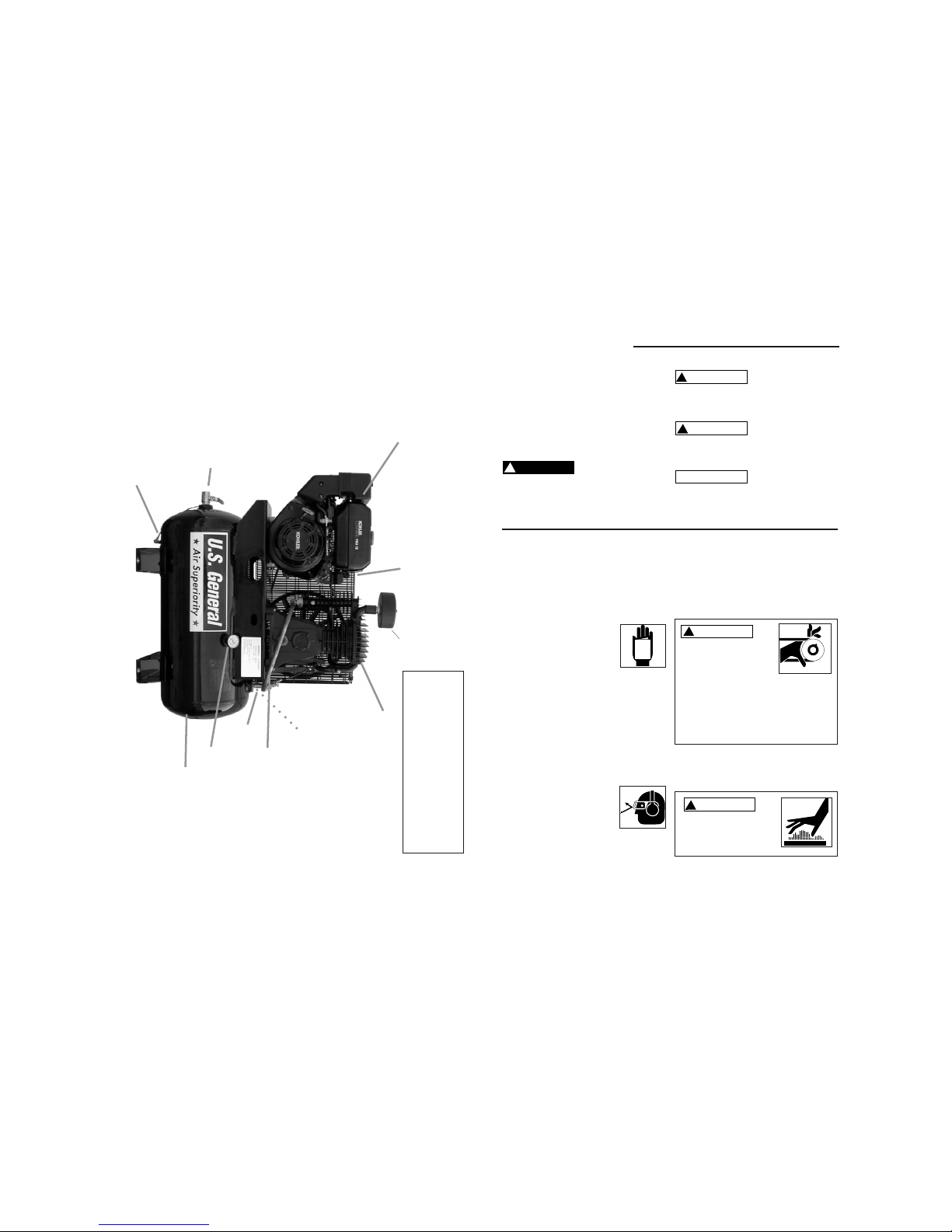
Operating Your Compressor
!
CAUTION
All lubricated compressor pumps dis-
charge some condensed water and oil
with the compressed air. Install appropri-
ate water/oil removal equipment and con-
trols as necessary for the intended appli-
cation.
NOTICE
Before starting the compressor,
thoroughly read all component
instruction manuals, especially the
engine manual.
NOTICE
Failure to install appropriate
water/oil removal equipment may
result in damage to machinery or
workpiece.
NOTICE
Do not attach air tools to open
end of the hose until start-up is
completed and unit checks OK.
To ensure proper operation, unit
must be on a level surface.
Moisture in compressed air will form into
droplets as it comes from an air compres-
sor pump. When humidity is high or when
a compressor is in continuous use for an
extended period of time, this moisture will
collect in the tank. When using a paint
spray gun, this water will be carried from
the tank through the hose, and out of the
gun as droplets mixed with the spray
material.
Moisture in Compressed Air
IMPORTANT: This condensation will cause
water spots in a paint job, especially when
spraying other than water based paints.
A filter in the air line, located as near to the
gun as possible will eliminate most of this
moisture..
Start-Up
3. Connect the negative (-) battery cable
to a mounting bolt or an acceptable
engine ground connection.
4. Connect the positive (+) battery cable
to the positive (+) battery terminal.
5. Connect the negative (-) battery cable
to the negative (-) battery terminal.
IMPORTANT: Number 2 wire or larger
is recommended.
1. Locate the starter solenoid terminal.
This is the top post farthest from the
block with the small red wire..
2. Connect the positive (+) battery cable
to the starter solenoid terminal.
Battery Connection
!
CAUTION
Make sure to follow instructions
carefully to avoid a short and poss-
ible damage to the starter solenoid
and/or battery. Always connect the
positive (+) battery cable to the
starter solenoid before connecting
the negative (-) battery cable.
1. Turn the gas lever to the “On” position.
Turn the choke lever to the left.
Turn key to the “On” position, then to
the “Start” position or pull start grip to
start the engine. Once the engine is
running, turn the choke lever to the
original “right hand” position.
See Engine Manual for More Detailed Instructions
Page 6
2. This compressor is equipped with an auto-
matic start- relief valve. This valve allows
the unit to run (unloaded) for a few
seconds before air pressure starts to build
in the tank.
3. When maximum tank pressure is reached,
the compressor automatically unloads,
slowing the engine to idle. The engine
remains at idle until tank pressure falls
to a preset level. The engine will then
accelerate and air will once again build
pressure in the tank.
4. To turn off compressor, turn key to the
“Off” position.
Note: Turn Gas Off when not in use.
Remember to drain moisture from tank
daily.
Operating Your Compressor (continued)
Adjusting A Regulator
(Regulator must be purchased Separately)
1. To adjust the regulator, pull out on the
regulator knob. Turn regulator knob
clockwise to raise outlet pressure and
turn regulator knob counterclockwise to
decrease outlet air pressure.
2. Once desired outlet pressure is obtained,
push regulator knob in to lock setting.
Maintenance
!
WARNING
Disconnect spark plug and drain
air system completely of all air
pressure prior to performing
maintenance on compressor..
NOTICE
Consult engine manual for scheduled
maintenance instructions.
DAILY
1. Check oil level at sight glass. Check
engine oil level.
2. Drain moisture from tank.
3. Visually check for loose parts or
excessive noise or vibration.
WEEKLY
1. Inspect air filter. Replace if necessary.
2. Check safety valve by pulling ring and
releasing. Valve should seal once
released.
3. Clean excessive dirt/dust from unit..
MONTHLY
Check belt tension and alignment.
3 Months
Change Oil. A compressor grade non-
detergent oil should be used.
Most automotive detergent oils cause excess
carbon build-up and should not be used.
Cold climates (Below 30°F) use 20WT
Moderate Climates (30°F-90°F) use 30WT
Hot Climates (Above 90°F) use 40WT
Page 7