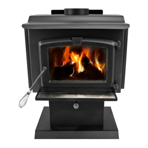
U.S. Stove Defender II User manual

Defender II
SAFETY NOTICE:
If this heater is not properly installed, a house re may result.
For your safety, follow the installation instructions. Never
use make-shift compromises during the installation of this
heater. Contact local building or re ofcials about permits,
restrictions and installation requirements in your area.
CAUTION!
Please read this entire manual before you install or use your
new room heater. Failure to follow instructions may result in
property damage, bodily injury, or even death. Improper
Installation Could Void Your Warranty!
Save these instructions. This manual will help you to obtain
efcient, dependable service from the heater, and enable
you to order repair parts correctly. Keep in a safe place for
future reference.
853363-0204i
CALIFORNIA PROPOSITION 65 WARNING:
This product can expose you to chemicals including carbon monoxide, which
is known to the State of California to cause cancer, birth defects and/or other
reproductive harm. For more information, go to www.P65warnings.ca.gov
Ce produit peut vous exposer à des produits chimiques, y compris le
monoxyde de carbone, qui est connu dans l'État de Californie pour causer
le cancer, des malformations congénitales et / ou d'autres problèmes de
reproduction. Pour plus d'informations, visitez www.P65warnings.ca.gov
Owner’s Manual Model: US1100E
U.S. Stove
227 Industrial Park Rd. South
Pittsburg, TN 37380, USA Phone:
(800)750-2723 www.usstove.com
Tested Per EPA Methods ALT-125, ASTM
E2515, ASTM E3053 and CSA B415
Certied to UL 1482-2011 (R2015) and
ULC-S627-00 (R2016)
Approved for mobile home installation
in USA and Canada
U.S. Environmental Protection Agency
Certied to comply with 2020
particulate emissions standards.
Report Number: F19-473
R

-2-
This manual describes the installation and operation of the Defender II, US1100E wood heater. This heater meets
the 2020 U.S. Environmental Protection Agency’s cordwood emission limits for wood heaters sold after May 15,
2020. Under specic test conditions this heater has been shown to deliver heat at rates ranging from 15,196 to
40,594 Btu/hr. Note: The BTU ratings mentioned above are based on the EPA test protocol under specic test
conditions. Our advertised BTU’s are based on the rst hour of operation at high burn rate burning dry cordwood.
CAUTIONS:
• HOT WHILE IN OPERATION. KEEP CHILDREN, CLOTHING AND FURNITURE AWAY. CONTACT MAY CAUSE SKIN
BURNS.
• DO NOT USE CHEMICALS OR FLUIDS TO IGNITE THE FIRE.
• DO NOT LEAVE THE STOVE UNATTENDED WHEN THE DOOR IS SLIGHTLY OPENED.
• DO NOT BURN GARBAGE, FLAMMABLE FLUID SUCH AS GASOLINE, NAPHTHA OR MOTOR OIL.
• DO NOT CONNECT TO ANY AIR DISTRIBUTION DUCT OR SYSTEM.
• ALWAYS CLOSE THE DOOR AFTER THE IGNITION.
Combustible: Wood
Colors: Metallic Black
Flue Pipe Diameter: 6” (153 mm)
Flue Pipe Type: (Standard Single Wall or Double Wall): Black or Blued Steel 2100°F (650°C)
Minimum Chimney Height: 12’ (3.7 m)
Maximum Log Length: 18” (458 mm)
Electrical: 120VAC, 0.55A, 60Hz
Dimensions
Overall:
Depth x Width x Height:
21.5” x 22.5” x 29.25”
(547 mm X 572 mm X 743 mm)
Combustion Chamber:
Width x Depth: 18.25” x 11.5” (464 mm X 293 mm)
Firebox Volume:
Cubic Feet: 1.35ft3
Door Opening: Width x Height: 16” x 9” (407 mm X 229 mm)
Pyroceramic Glass Door: (Viewing) Width x Height: 15” x 8” (381 mm X 204 mm)
Weight (lbs): 180 lbs
UNPACK AND INSPECT
Remove the packing from the appliance and inspect for any damage. Your appliance is packed with the door
handle spring not installed. Ensure that the bricks are positioned correctly and not broken (see illustration for
proper brick arrangement). Make sure that the bafe board, above the air tubes, is in place and undamaged.
(DO NOT REMOVE).
Brick Conguration
Note: Register your product on line at www.usstove.com. Save your receipt with your records for any claims.

-3-
Step 1 - THE BLOWER ASSEMBLY MUST BE DISCONNECTED FROM THE SOURCE OF ELECTRICAL SUPPLY BEFORE
ATTEMPTING THE INSTALLATION. With pliers, cut the 4 tabs and remove panel on the back of the stove. Note:
Discard the panel.
Step 2 - Fix the assembly to the back of the stove with the four screws provided. THE BLOWER ASSEMBLY IS
INTENDED FOR USE ONLY WITH A STOVE THAT IS MARKED TO INDICATE SUCH USE. DO NOT ROUTE THE SUPPLY CORD
NEAR OR ACROSS HOT SURFACES!
Assembly
Installation
SAFETY NOTICE
• IF THIS STOVE IS NOT PROPERLY INSTALLED, A HOUSE FIRE MAY RESULT. TO REDUCE THE RISK OF FIRE, FOLLOW
THE INSTALLATION INSTRUCTIONS.
• CONSULT YOUR MUNICIPAL BUILDING DEPARTMENT OR FIRE OFFICIALS ABOUT PERMITS, RESTRICTIONS AND
INSTALLATIONS REQUIREMENTS IN YOUR AREA.
• USE SMOKE DETECTORS IN THE ROOM WHERE YOUR STOVE IS INSTALLED.
• KEEP FURNITURE AND DRAPES WELL AWAY FROM THE STOVE.
• NEVER USE GASOLINE, GASOLINE-TYPE LANTERN FUEL, KEROSENE, CHARCOAL LIGHTER FLUID, OR SIMILAR
LIQUIDS TO START OR “FRESHEN UP” A FIRE IN THIS HEATER. KEEP ALL SUCH LIQUIDS WELL AWAY FROM THE
HEATER WHILE IT IS IN USE.
• IN THE EVENT OF A CHIMNEY FIRE, PUSH THE AIR CONTROL FULL CLOSED TO DEPRIVE THE FIRE OF OXYGEN.
CALL THE FIRE DEPARTMENT.
• DO NOT CONNECT TO ANY AIR DISTRIBUTION DUCT OR SYSTEM.
• A SOURCE OF FRESH AIR INTO THE ROOM OR SPACE HEATED SHALL BE PROVIDED WHEN REQUIRED.
• ONLY OPERATE THE STOVE WITH THE DOOR CLOSED. OPERATING WITH THE DOOR OPEN COULD CAUSE
OVERFIRING.
POSITIONING THE STOVE
It is very important to position the wood stove as close as possible to the chimney, and in an area that will favor
the most efcient heat distribution possible throughout the house. The stove must, therefore, be installed in the
room where the most time is spent and in the most spacious room possible. Recall that wood stoves produce
radiating heat, the heat we feel when we are close to a wood stove. A wood stove also functions by convection,
that is through the displacement of hot air accelerated upwards and its replacement with cooler air. If necessary,
the hot air distribution from the stove may be facilitated by the installation of a blower. Route power cord away
from unit. Do not route power cord under or in front of appliance. The wood stove must not be hooked up to a
hot air distribution system since an excessive accumulation of heat may occur.
FLOOR PROTECTOR
This heater must have a non-combustible oor protector (ember protection) installed beneath it if the oor is
of combustible material. If a oor pad is used, it should be UL listed or equal. The oor pad or non-combustible
surface should be large enough to extend under the stove and beyond each side as indicated. If there is a
horizontal run of ue pipe, there needs to be oor protection under it that extends two inches beyond either side
of the pipe.

-4-
FLOOR PROTECTOR DIMENSIONS
H
J
K
L
MN
P
Q
Key Dimension Inch mm
HStove Width 22.48 571
JStove Depth 20.76 528
*K Front 16 407
LBack 2 51
M Left 8 204
NRight 8204
P Total Width 38.48 978
Q Total Length 38.76 985
* Canadian installations require 18” (457mm)
FREE STANDING STOVE CLEARANCES
A wood stove must never be installed in a hallway or near a staircase, since it may block the way in case of re
or fail to respect required clearances. It is of utmost importance that the clearances to combustible materials be
strictly adhered to during installation of the stove. Refer to the tables below:
• Do not place any combustible material within 4’ (1.2m) of the front of the unit.
• The clearance between the ue pipe and a wall are valid only for vertical walls and for vertical ue pipe.
• The chimney connector must not pass through an attic or roof space, closet or similar concealed space, a
oor, or a ceiling.
• For Canadian installations, where passage through a wall, or partition of combustible construction is desired,
the installation must conform to CAN/CSA-B365.
• A ue pipe crossing a combustible wall must have a minimum clearance of 18” (457.2mm).
• To reduce ue clearances from combustible materials, contact your local safety department.
Key Dimensions Inch mm
ABackwall to Stove 17 432
B Sidewall to Stove 21 534
CWall to corner (Angled Installation) 14 356
D Ceiling Height 84 2134
EBackwall to Flue 20 508
F Sidewall to Flue 29 737
G Wall to Flue (Angled Installation) 22 559
CLEARANCE TO WALLS
Side wall
Backwall
Side wall
Backwall
CORNER INSTALLATION
CLEARANCE TO WALLS
Ceiling
CORNER INSTALLATION
CLEARANCE TO
WALLS & CELING

-5-
SPECIAL MOBILE HOME REQUIREMENTS
WARNING! - Do not install in a sleeping room
CAUTION! - The structural integrity of the mobile home oor, wall, and ceiling/roof must be maintained.
In addition to the previously detailed installation requirements, mobile home installations must meet the following
requirements:
• The space heater is to be connected to a factory-built chimney conforming to CAN/ULC-S629, Standard for
650°C Factory-Built Chimneys.
• The heater must be permanently attached to the oor. There are two holes in the pedestal base, use 3/8”
bolts through the oor.
• The heater must be electrically grounded to the steel chassis of the mobile home with 8 GA copper wire
using a serrated or star washer to penetrate paint or protective coating to ensure grounding.
• When moving your mobile home, all exterior venting must be removed while the mobile home is being
relocated. After relocation, all venting must be reinstalled and securely fastened.
• Outside Air is mandatory for mobile home installation. See your dealer for purchasing.
• Check with your local building ofcials as other codes may apply.
• Only use the specied components listed in this manual for this unit. The use of components that are not
meant for this unit can cause unsafe conditions.
COMBUSTION AIR ASSEMBLY INSTRUCTIONS
This appliance requires a source of combustion air. If your home is of tight construction or has negative pressure
problems, you will need an outside source of air. Below is a list of possible indicators that a source of outside
combustion air may be required.
MOBILE HOME INSTALLATIONS - REQUIRED
• Your stove does not draw steadily, smoke rollout occurs, wood burns poorly, or back-drafts occur whether or
not there is combustion present.
• Existing fuel-red equipment in the house, such as replaces or other heating appliances, smell, do
not operate properly, suffer smoke roll-out when opened, or back-drafts occur whether or not there is
combustion present.
• Opening a window slightly on a calm (windless) day alleviates any of the above symptoms.
• The house is equipped with a well-sealed vapor barrier and tight tting windows and/or has any powered
devices that exhaust house air.
• There is excessive condensation on windows in the winter.
• A ventilation system is installed in the house.
If an outside air intake is required, you may purchase a standard 4” Dryer Vent kit from your local hardware
supply store and install it on the rear of the appliance.
When using a Dryer venting kit, the outlet cover must be of a design that DOES NOT close by means of a ap
or trap door. You must purchase a style that allows a continuous in-ow of air and that has a rodent screen. This
adapter can be purchased from your dealer.
4FAK INSTALLATION
Follow the manufacturer’s installation instructions for attaching the dryer vent kit to the home. Then, attach it to
the adapter on the combustion air inlet on the back of the pedestal as shown.
“Dryer Venting Kit”
Installation
Slide the hose clamp over the aluminium ex pipe. Then slide the ex pipe
over the air intake tube of the stove. Next tighten the hose clamp over the
end of the aluminium ex hose.
Table of contents
Other U.S. Stove Wood Stove manuals
Popular Wood Stove manuals by other brands

RAIS
RAIS attika NEXO 100 GAS installation guide

WoodPro
WoodPro WS-TS-1500 owner's manual

Contura
Contura C 586W installation instructions

Palazzetti
Palazzetti EVA GENERAL INFORMATION - WARNINGS - INSTALLATION - MAINTENANCE

Lopi
Lopi 1250 Republic owner's manual

Panadero
Panadero CAPRI 3V Usage and maintenance instructions