UAT ADSL USB NIC User manual

EXHIBIT C
User Manual

Installation Guide For UAT ADSL USB Modem
1
ADSL USB NIC User Manual
Revision 1.0
01-10-2001
T is document contains confidential information and is
proprietary to UAT Inc.
No part of t is document may be reproduced in any form or by any means
wit out t e prior permission of UAT Inc.
All specifications are subject to change without notice.
UAT Inc.
2F, No.5, Alley22, Lane 513, Jui Kuang Rd,
Nei Hu, Taipei
Taiwan, R.O.C
Tel: (886) 2 8797 8488
Fax: (886) 2 2657 0997

Installation Guide For UAT ADSL USB Modem
2
elcome to ADI USB ADSL Modem!
Introduce yourself to t e new world of fast Internet. ADI provides a w ole new fast and
simple plug-n-play Universal Serial Bus (USB) Windows environment for Internet access.
T e ADI ADSL USB Modem contains a complete evaluation package including ardware
reference design, Windows software drivers, test/utility software, design documents,
performance reports and t is user manual.
T e manual is written based on t e ADI ADSL USB Modem ardware release Version 3.1.3,
t e software release Version Alp a01 and t e ADIMON GUI Ve rsion 2.5.
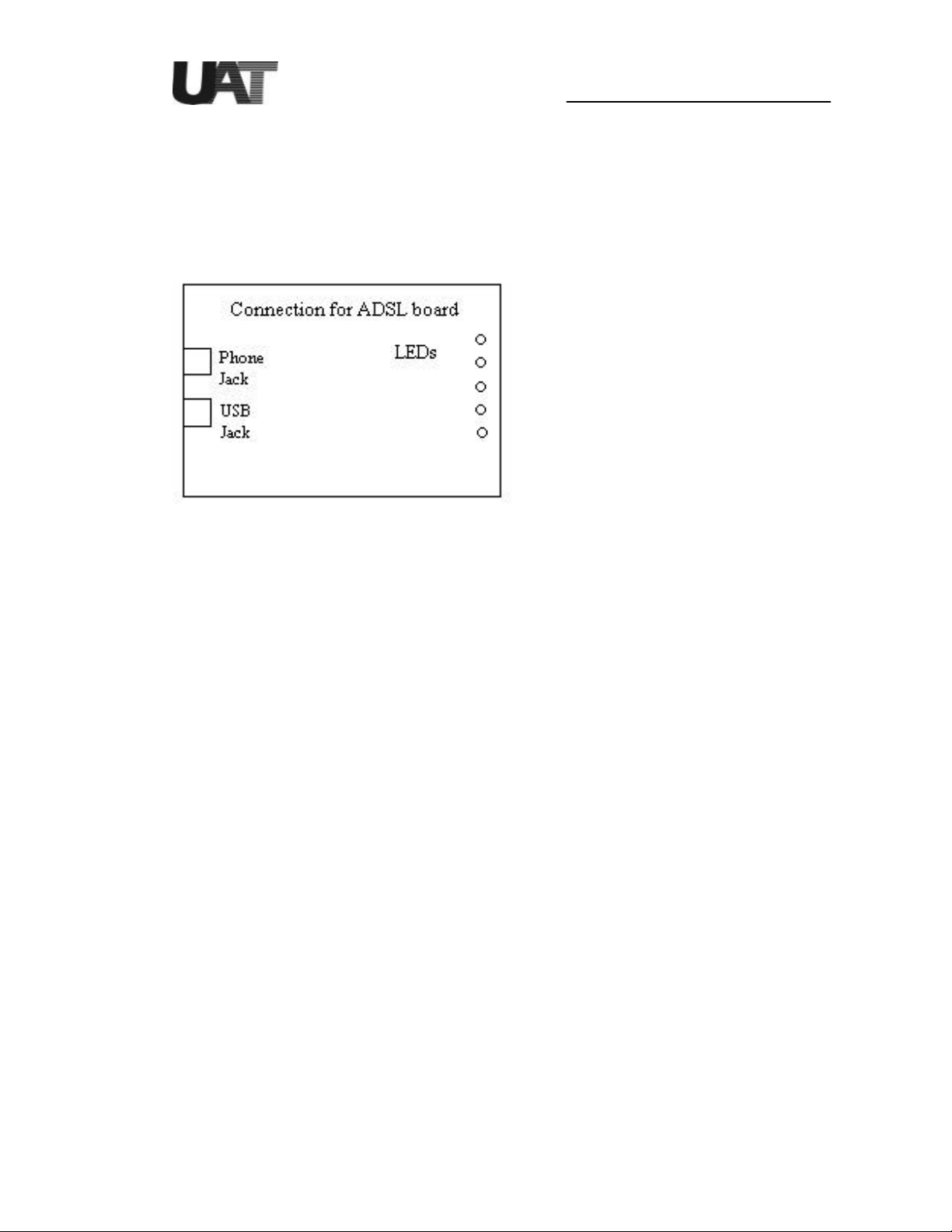
T e ADI ADSL USB Modem features:
?? Plug and Play USB 1.1 specification interface
?? Rate Adaptive ADSL tec nology t at adapts to your p one line conditions
?? Receive line rate up to 10Mbps (downstream) and transmit line rate up to 1Mbps
(upstream)
System Requirements
To use t e USB Modem, your PC or notebook s ould ave:
?? Pentium 233MHz CPU or faster
?? 32MB system memory or more
?? 3MB free space on your ard drive
?? 256 color VGA or ig er resolution
?? Microsoft Windows 98 or Windows 98 Second Edition CD-ROM
?? Floppy drive and CD-ROM drive
?? One available USB port and one USB cable
?? RJ11 p one wire
?? DSLAM or central office modem ready
T e s ielded USB cable is to be used in order to ensure compliance wit FCC Part 15,
and it is t e responsibility of t e user to provide and use s ielded USB cable from modem
to personal computer.
CAUTION: Any c anges of modifications not expressly approved by t e grantee of t is
device could void t e users aut ority to operate t e equipment.
Document Annotations
Important Instruction
Special Note

Installation Guide For UAT ADSL USB Modem
3
Hardware Installation
Familiarizing yourself with your USB ADS Modem
Your modem as one RJ-11 p one jack and USB cable jack receptacle for data connection.
POTS splitters or microfilters can be required to work concurrently wit conventional POTS
equipment suc as p one, fax and V.90 modem. Various LEDs display modem status.
Installing the ADS USB modem
To install t e modem:
1. Turn on your computer and run Windows 98.
2. Plug USB cable from main computer to modem.
3. Connect your modem using standard p one wire and plug t e ot er side of t e wire
to your ouse p one jack w ic is connected to central office modem provided by
service provider.
4. Windows USB plug-n-play feature s ould automatic ally recognize t e modem and ask for
software installation.

Installation Guide For UAT ADSL USB Modem
4
Driver Install
To install t e drivers for Windows 98, plug t e modem to system using USB cable before
power up t e PC or after Windows is running:
1. Windows 98 PnP detects t e USB modem USB devices. Click on “Next” from below
screen.
2. Let Windows 98 searc for t e best driver.

Installation Guide For UAT ADSL USB Modem
5
3. Select floppy disk or CD-ROM (recommended) w ic contain “E:/ driver/USB/00-12-20/
cpe sw ndis sw ndis usb alp a01 for Windows 98 to install t e USB firmware loader.
Click on “Next” to continue.
4. Windows 98 detects t e ADI USB firmware loader. Click on “Next” to continue.
5. Click on “Finis ”. ADI firmware is being loaded into t e system.

Installation Guide For UAT ADSL USB Modem
6
6. Click on “Yes” to re start t e PC.
7. Next is to install t e ADI USB modem device driver “ADIUSBAE” into t e system.
Windows 98 PnP automatically detects t e modem and click “Next” to continue.
8. Let Windows 98 searc for t e proper device driver.

Installation Guide For UAT ADSL USB Modem
7
9. Select floppy disk or CD-ROM(recommended) w ic contains “ADIUSBAE.SYS” and
“ADIUSBAE.INF” for Windows 98 to install t e USB device driver. Click on “Next” to
continue.
10. Follow t e installation dialogs to install t e driver.

Installation Guide For UAT ADSL USB Modem
8
11. Now restart t e computer as t e system asks.
Note: Unplug the USB cable and do not plug it back until system finishes running
indows. Otherwise, unexpected crash might be occurred.

Installation Guide For UAT ADSL USB Modem
9
ADIMON USB User Interface GUI Setting Up
After t e PC being restarted, please go to t e Start Menu->Program-> Windows
Explorer->[E:]->Driver->USB->00-12-20-> cpe sw ndis usb alp a01, for ADIMON USB
User Interface setting up.

Installation Guide For UAT ADSL USB Modem
10
Changing USB driver parameters
To verify t e modem is properly installed, open “Control Panel” and click on “System” icon.
In t e “Device Manager” window you s ould see t e “ADI USB ADSL Modem” in t e
“Network adapters” list entry. C eck USB modem “Properties” to see w et er modem is
successfully installed.
1. Wit out unplug t e USB modem, open “Control Panel” t en select “Network” panel.
2. Select “ADI USB ADSL modem” t en click on “Properties”.

Installation Guide For UAT ADSL USB Modem
11
3. Click on “Advanced” tab. and c ange desired driver parameters from t e following
windows:
Click on “OK” and back to t e Network window to c ange t e TCP/IP Net work Settings.
Changing the TCP/IP Network Settings
Click on t e “Network” icon to display t e network status. Hig lig t “TCP/IP ->ADI USB
ADSL Modem” and click on “Properties”.
Obtain all t e TCP/IP setup information from your network administrators in order to
configure t e TCP/IP protocol. If DHCP server is not available from t e CO side, enter
t e IP address and subnet mask. Also enter t e DNS and Gateway information w en
necessary.

Installation Guide For UAT ADSL USB Modem
12
After t e IP address being set, please go to Network->ADI USBADSL loader, click on
“Properties” and set t e same IP address as in t e above procedure.
Now restart t e PC again as t e system requires.
Modem Parameter Descriptions
CMV OPTN x
Current ADI modem firmware CMV parameter values can be viewed and c anged ere.
Refer to t e ADI ADSL modem software specification for details.
C ange LineType greater t an 4 to trigger t e software driver to pass all t e non-default
OPTN values. If LineType is less t an 5, driver uses internal OPTN default values
regardless of your new settings. Unless you are familiar wit OPTN CMVs, do not c ange
t ese parameters.
Debug Level
T is entry is used for modem debug and development. It sets different levels of debug
print messages. It can be any combinations of t e following values:
0: Minimum messages
1: Errors only
2: Trace only
4: Detail messages only
For example, if you set it to 7 (4+2+1) it prints all debug messages to t e debugger.
Default value is set to 10.
Debug Module
Defines t e modules need to be debugged. Default is 0xFFFFFFFF w ic covers all t e
modules.
DMT state timer
Time interval to send and receive CMV messages to train t e modem in milliseconds.
Default is 200.
IDMA Boot
Modem firmware can be loaded eit er from t e on-board Flas device (default) or from t e IDMA interface
(Flas less boot) of t e modem. C ange value to 1 for IDMA Boot.
In t e current software driver release, only Windows 98 Second Edition supports IDMA Boot option.
Line Type
Select default CMV settings for ADSL line types: T1.413, G.DMT or G.LITE.
0: G.LITE
OPTN0 = 0x00900044
OPTN2 = 0x23700000
OPTN4 = 0x321

Installation Guide For UAT ADSL USB Modem
13
PFCL1 = 0x0000000a
1: G.DMT
OPTN0 = 0x00000044
OPTN2 = 0x23700000
OPTN4 = 0x111
2: T1.413
OPTN0 = 0x00000044
OPTN2 = 0x23700000
OPTN4 = 0x2
4: Default setting
OPTN2 = 0x23700000 (only setting)
ADSL firmware is currently defaulted to T1.413.
Number o RX Bu er
Driver receive buffer sizes are 50 (minimum), 1024 (maximum), 50 (default).
Number o TX Bu ers
Driver transmit buffer sizes are 50 (minimum), 1024 (maximum), 50 (default).
Retrain
Time interval to receive CMV messages from modem in msec after modem is successfully
trained. T is value affects t e line re-train response time. Default value is 300.
RFC1483 VCI
Default value is 32. T is s ould matc wit central office modem value.
RFC1483 VPI
Default value is 0. T is s ould matc wit central office modem value.
RFC1483Mode
Value 0 indicates Et ernet driver.
Value 2 indicates IP driver.
After c anging t e desired parameter value(s), click “OK” to close t e “Modem Properties”
windows. W ile t e system asks for reboot, eit er reboot t e PC or simply unplug t e
USB cable, wait a few seconds and plug back to t e modem. New values will t en be
loaded into t e system.

Installation Guide For UAT ADSL USB Modem
14
After t e ADSL USB modem as been successfully installed. ADIMON GUI can be opened
from Start Menu ->Program->Adiusb. Double click on t e “ADIMON’ icon.
T e first screen is t e Summary Window, w ic s ows t e ADSL modem status including
ADSL line and data rates.

Installation Guide For UAT ADSL USB Modem
15
Information Field Description
Transmit Line Rate Upstream data rate negotiated by t e ADSL link (Kbit/s)
Receive Line Rate Downstream data rate negotiated by t e ADSL link (Kbit/s)
Transmit Data Rate Actual user data transmit rate (Kbit/s)
Receive Data Rate Actual user data receive rate (Kbit/s)
Modem Status Status of t e modem:
(IDLE, OPERATIONAL, INITIALIZING, FAILED)
T e Details Window provides detailed information for t e ADSL, ATM and Packets
parameters. T e information is grouped accordingly to DSL, ATM and PACKETS. T e
meanings of eac field are listed in t e table below.

Installation Guide For UAT ADSL USB Modem
16
DSL Information
Field
Description
ADSL Standard ADSL Standard (ANSI T1.413, G.DMT, G.LITE, Multi-Standard)
Transmit Rate Upstream data rate negotiated by DSL link (Kbit/s)
Receive Rate Downstream data rate negotiated by DSL link (Kbit/s)
CRC Number of errors per second since training
Margin Near end (CPE) current SNR margin (dB)
Attenuation Current attenuation (dB)
VID-CPE Vendor ID of t e DSL ATUR
VID-CO Vendor ID of t e DSL ATUC
FEC Number of uncorrectable errors since start of link
ATM
Information Field
Description
Transmitted Cells Number of (non-IDLE) ATM cells transmitted since start of link
Received Cells Number of (non-IDLE) ATM cells received since start of link
Delineation ATM delineation status: LOSS or GOOD. GOOD implies t at
ATM Sync is ac ieved and maintained.
VPI Virtual Pat Identifier field used in t e ATM cell eader
VCI Virtual C annel Identifier field used in t e ATM cell eader
HEC Number of received ATM cells wit errors in t e ATM cell eader
since start of link.
Packet
Information Field
Description
Transmitted Number of AAL5 packets transmitted since start of link
Received Number of AAL5 packets received since start of link
Total Loss Number of AAL5 packets received t at are discarded (due to CRC
errors and oversize)
Loss % Percentage of AAL5 packets received t at are discarded
CRC Number of A AL5 packets wit c ecksum errors
Oversized Number of oversized packets received
T e Configuration Window allows users to c ange t e modem configuration information.
For configuration c anges to take effect, t e USB modem is required to unplug and plug
back from t e USB cable (or simply reboot t e PC).

Installation Guide For UAT ADSL USB Modem
17
Information Field Description
ATM T e VPI and VCI values can be c anged ere, t e values are to be
entered using decimal format
Encapsulation For t e NDIS driver, c oices include Bridge LLC SNAP, Bridge VC
MUX, Route LLC SNAP or Route VC MUX. NDISWAN driver
selection will be added in later release version.
ADSL Standard C oices are ANSI T1.413, G.LITE, G.DMT and Multi-Standard
T e Version Window can be opened from t e Details Windows.
Information Field Description
ADIMON GUI version
Hardware Evaluation board version
Driver Windows device driver version
Firmware DSL modem firmware version
VxD Virtual device driver version
T e ADIMON GUI consists of a User Interface (written using MFC and compiled under
Visual C++ 6.0) and a Virtual Device Driver (VxD) t at facilitates information s aring
between t e USB device driver and t e user interface (compiled using Windows 98 DDK).
For product customization, source code is available upon request.

Installation Guide For UAT ADSL USB Modem
18
Uninstall the USB ADSL modem
To uninstall t e modem:
1. From Windows Start menu, c oose Programs->Adiusb and click on “UNINST”. Click
“ Yes” to confirm file deletion, UNInstallS ield will remove t e related files
2. From Windows Start menu again, c oose Settings->Control Panel and select “Network”
properties. Hig lig t “ADI USB ADSL Loader” and “ADI USB ADSL Modem” and
remove bot entries. Click on “OK” to exit. Restart t e PC w ile system asks.
3. Unplug t e USB modem.

Installation Guide For UAT ADSL USB Modem
19
Troubleshooting the Modem
Please read t e following Q&A to elp debugging t e problems wit your ADI ADSL USB modem.
USB driver is not re-loaded after unplug and plug back the USB cable to modem.
C eck “Device Manager” from “System Properties”, delete unknown USB device(s) if any.
After followed driver installation procedures, modem is still not working.
One obvious way is to c eck on board LED status. Provided DSLAM is ready for operation, LED D6 s ould
be “blinking” (default setting) for t e central office modem detection. Make sure line type selection matc es
wit w at DSLAM supports.
hich OS works the best?
Bot Windows 98 and Windows 98 2nd Edition are supported. Windows 98 2nd Edition supports USB bus
power management and Native ATM functions, t erefore it is recommended to use. Most versions of
Windows 95 and Windows NT do not support USB. Windows Millennium and Windows 2000 will be fully
supported in future software releases. Consult your local ADI representatives for release sc edules.
How do I know if ADI USB driver is installed correctly?
Open “Network Panel” from “Control Panel” folder. “ADI USB ADSL Modem” entry under t e Adapter tab
s ould exist. Click on its “Properties”, it will s ow t at USB is corr ectly installed or not. Also select
“Device Manager” menu from “System” properties of “Control Panel” to c eck t e existence of USB driver
from “Network adapters”.
Is my modem trained correctly?
LED D6 s ould remain “ON” w en t e modem is correctly linke d to t e central office modem. T e blinking
rate of LED D9 indicates ow frequent CRC errors occur in t e ADSL modem. Excessive CRCs will cause
rate reduction in data flow.
Is the line passing data?
To determine if data flow is occurring, execute t e program “Netstat.exe” (e.g. “netstat –e” to view Et ernet
statistics) from a DOS Window. If data flow is occurring, t e values given by Netstat s ould be increasing
every time it is executed.
How do I set modem IP address?
To determine t e modem IP address, execute t e program “ipconfig.exe” (e.g. “ipconfig /all”) from a DOS
Window. T e IP address is s own on t e line “IP Address”. For example: IP Address . . . . . . . . . : 196.168.0.2
Consult your network administrator or service provider to determine if it is valid or not. IP address is set in
“Network Panel” from “Control Panel” folder. Double click on “TCP/IP ->ADI USB ADSL Modem” to
c ange IP address.
Can’t install the device driver?
If you ave installed previous release versions of device driver, ext ra uninstall steps are required:
- Remove "ADI USB ADSL Modem" and "ADI USB ADSL Loader" from Control Panel->Network
Properties.
- Searc and delete *ADIUSB*.*, *ADILOAD*.* and *ADILDR*.* files under all t e
subdirectories of Windows (suc as C:\Windows). T en unplug and plug back t e USB
modem, remove "ADI Modem Firmware" from System Properties->Device Manager.
- Reboot PC before new driver installation.
Table of contents
Popular Modem manuals by other brands

Option Wireless Technology
Option Wireless Technology iCON 505M user guide

Patton electronics
Patton electronics 1058DVs Product Quick Reference

Patton electronics
Patton electronics 2703 user manual

Abocom
Abocom FM56CC Specifications

Linksys
Linksys ADSL2MUE Product data

Intel
Intel 536EPXX - PRELIMINARY datasheet