UAV-1001101-001 Page 9 | 26
7 Installation
7.1 Magnetic Mounting
The Vektor comes with strong rare earth magnetic mounts designed
specifically to hold the unit in place at speeds up to 165 kmh (100 mph).
This ensures that the transponder may remain installed during normal
airfield operations or when the vehicle is operating on public motorways.
To mount the transponder, ensure that roof of the vehicle is made of metal,
magnetic mounts will not attach with sufficient force to fiber glass or
aluminum roofs. In addition, before placing the unit on the roof, ensure that
the area is clean of dust, debris or rust. To ensure proper contact with the
roof, the area of the roof should present a flat, uniform surface. Areas with
ridges and irregular contours should be avoided.
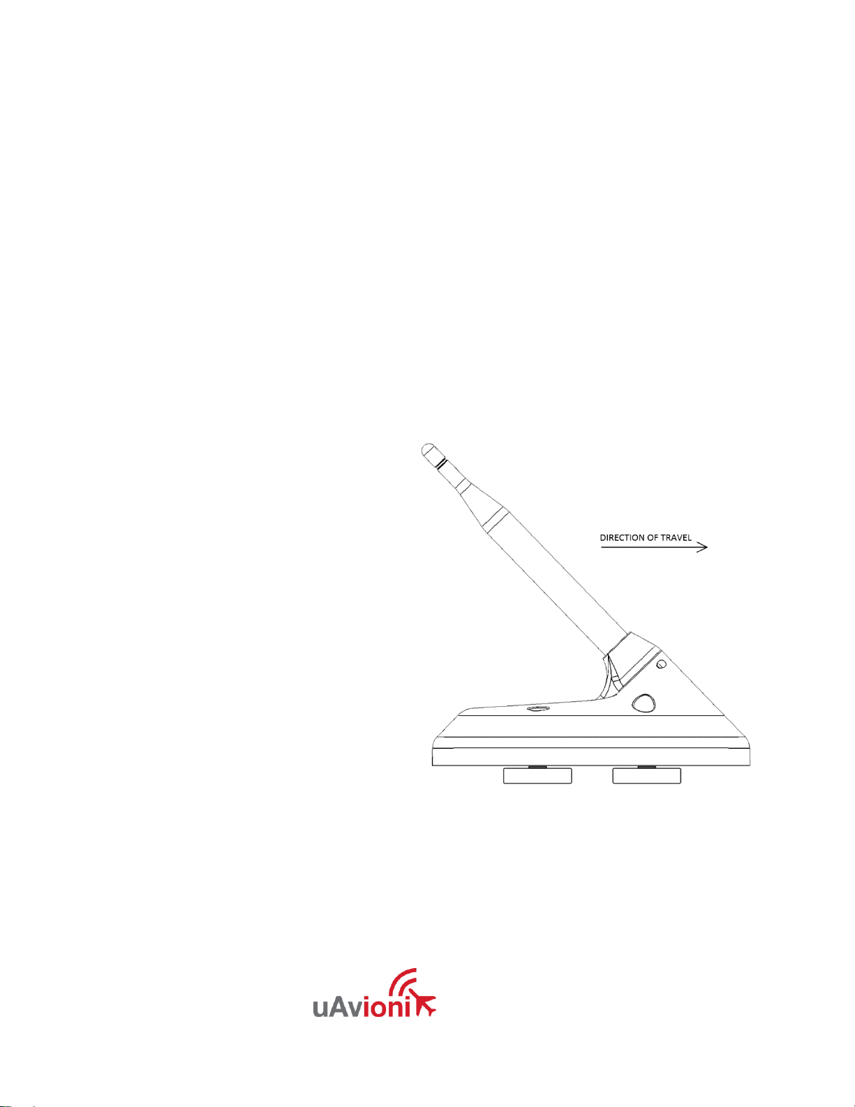
To minimize unnecessary wind
loading of the unit, align the unit
to the front of the vehicle or the
primary direction of travel. In
addition, to ensure GPS
accuracy and minimize time to
position lock, the unit should
have a clear line of sight to the
sky. To mitigate reflections or
blocking of 1090 MHz
transmissions, the unit should
be a minimum of 12 cm from
other roof mounted equipment
such as warning lights, and 50
cm from other radio frequency
emitting antennas.
The power cable from unit will protrude from the bottom of the unit and the
magnetic mounts provide sufficient clearance for the cable. The area where
the cable makes entry into the unit has been weatherproofed to ensure
compliance with IP67 moisture and dust penetration standards.