UberFly Super Honey Hawk Manual

Table of Contents
Contents
Table of Contents..............................................................................................................................................2
Preamble...........................................................................................................................................................4
Required Materials ............................................................................................................................................4
Tools / Supplies..........................................................................................................................................4
Finishing Parts............................................................................................................................................5
Build Steps........................................................................................................................................................7
Cut Out or Dislodge The Pieces.....................................................................................................................7
Chamfer the Control Surfaces........................................................................................................................7
Glue the Horizontal Parts together.................................................................................................................7
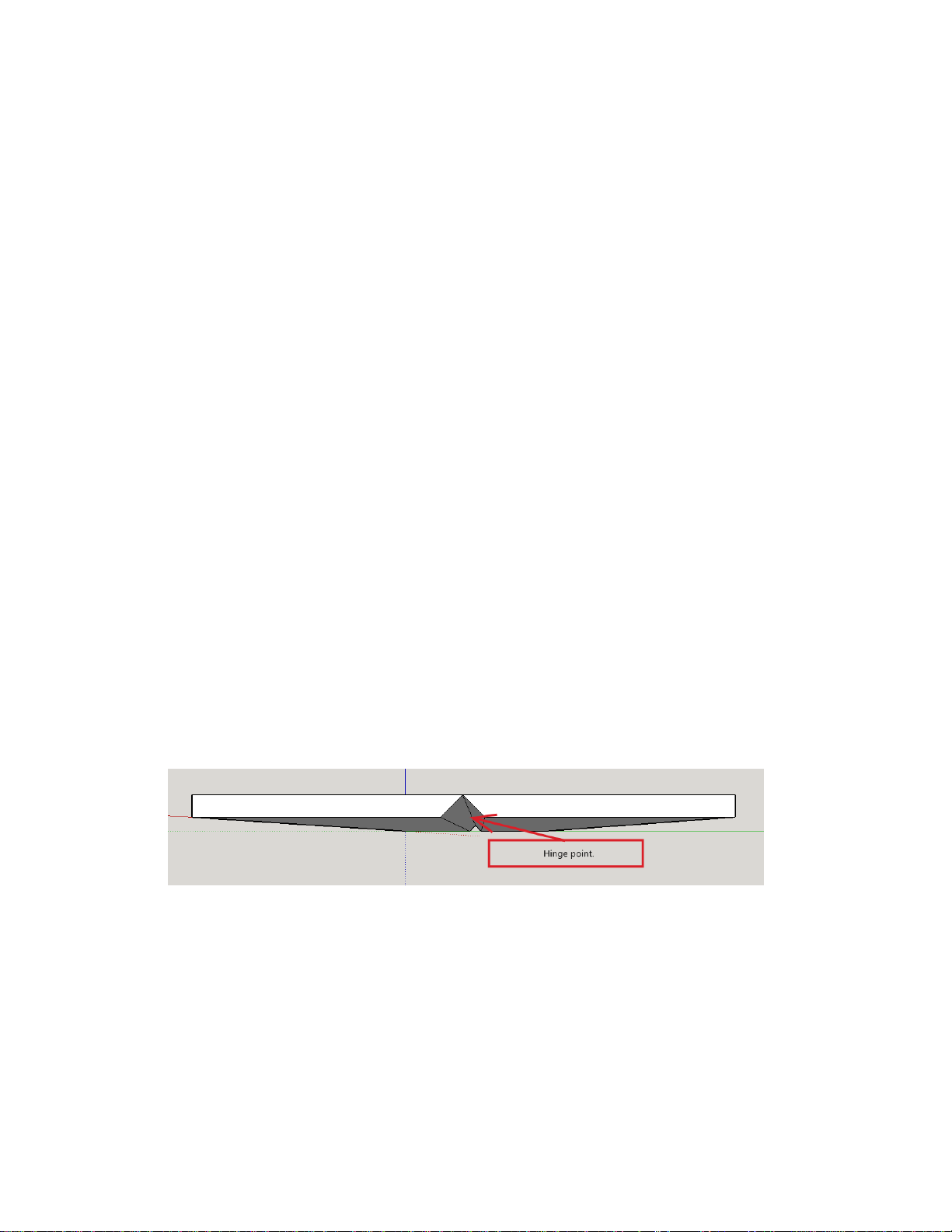
Attach the Ailerons and Elevator....................................................................................................................7
Glue in the Carbon Spars...............................................................................................................................8
Wing & Tail Spars.......................................................................................................................................8
Fuse Spar Joiner........................................................................................................................................8
Prepare and mount the Servos ......................................................................................................................8
Mount Aileron Quick Link Connectors.........................................................................................................8
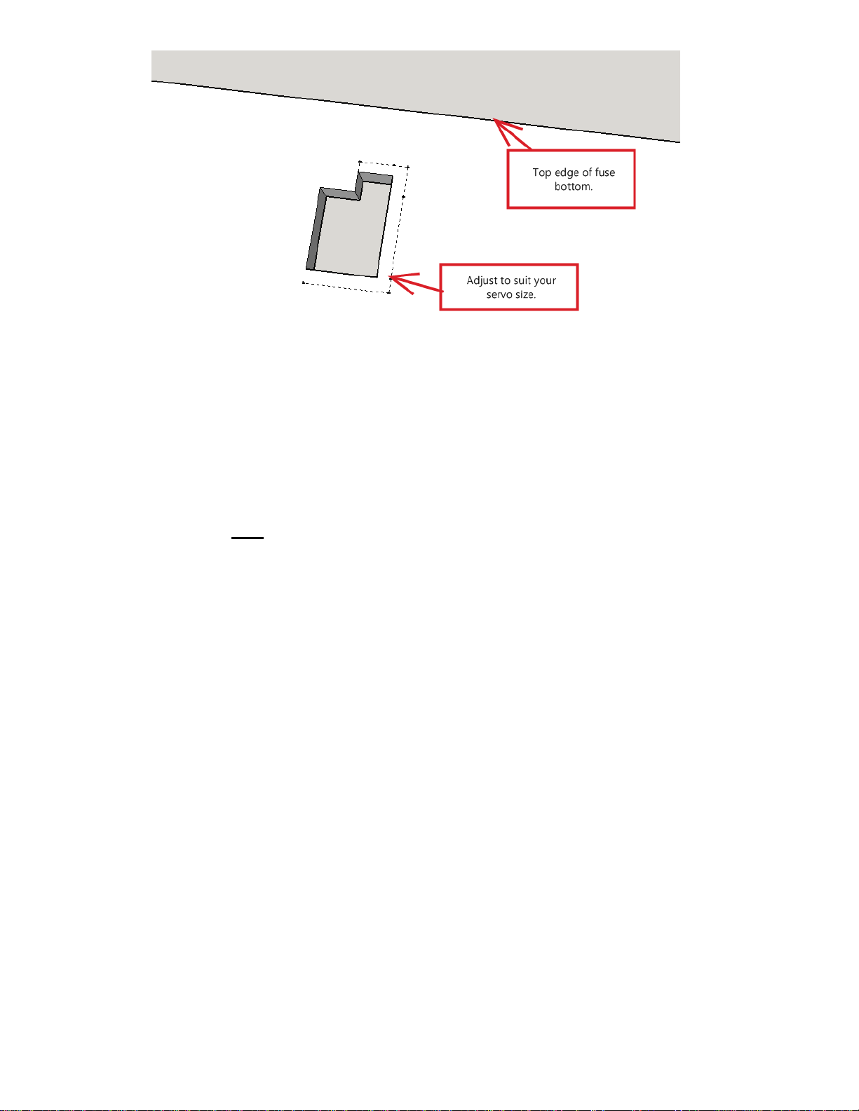
Mount the Servos .......................................................................................................................................9
Glue the bottom fuse onto the Horizontal parts ............................................................................................10
Mount aileron and elevator servo linkages...................................................................................................10
Ailerons....................................................................................................................................................10
Elevator....................................................................................................................................................10
Glue the top fuse onto the Horizontal parts..................................................................................................11
Glue the rudder onto the fuse.......................................................................................................................11
Install the Tail Rotor.....................................................................................................................................11
Remove Tail Rotor Foam..........................................................................................................................11
Install Tail Rotor Motor Mount...................................................................................................................11
Install Fuse Joiners...................................................................................................................................12
Install Tail Rotor Carbon Supports............................................................................................................12
Mount Tail Motor ......................................................................................................................................13
Install tail bracing.........................................................................................................................................13
Mount rudder servo linkages........................................................................................................................14
Mount the nose motor..................................................................................................................................14
Mount electronics.........................................................................................................................................14
Glue on the Side Force Generators..............................................................................................................14
Optionally add landing gear..........................................................................................................................15
Post Build........................................................................................................................................................16
Center all Servo Channels and Controls ......................................................................................................16
Tail Rotor Subtrim / Centering......................................................................................................................16
Program Tail Rotor Mixing ...........................................................................................................................16
Control Throws / DR & Expo........................................................................................................................17

Mount Propellers..........................................................................................................................................17
Pre Flight Checks............................................................................................................................................18
Check Center of Gravity (CG) location......................................................................................................18
Control Directions.....................................................................................................................................18
Motor Direction.........................................................................................................................................18
Motor Direction –Tail Rotor......................................................................................................................18
Maiden Flight...................................................................................................................................................18
Pinwheels.................................................................................................................................................19
Epilogue..........................................................................................................................................................19

Preamble
The following document outlines the build process for the UberFly.ca Super Honey Hawk. It is not an
exhaustive instruction guide, but expects a certain level of proficiency on the part of the builder. If questions
arise during the build they can be emailed to help@uberfly.ca and we’ll get back to you with answers -
assuming we have them.
Required Materials
The following are required to build the Super Honey Hawk. Please ensure you have these at hand
before beginning the build. Substitutions can be made where it makes sense and where your flavour of
electronics and/or hardware suits you. Alternates can be suggested if you like just let us know via email to
help@uberfly.ca.
Tools / Supplies
○Flat surface to build on - especially important when gluing carbon onto the flat surfaces... glue
them on a warped surface and get a warped plane!
○Very sharp X-Acto knife OR razor blades - dull blades just make a mess of foam.
○Glue:
The EPP that the Super Honey Hawk is made of has been tested with the following glues,
but others (such as wood or craft glue, etc.) could be used... simply test on some of the
scrap foam:
■Foam Tac glue by Beacon Adhesives for most foam-on-foam glueing
●Alternates:
○Bob Smith's "EPP Glue" is similarly flexible to Foam Tac
○Foam to Foam glue by deluxematerials.com
○Hot Glue (careful not to melt the EPP)
○Foam Safe CA (thin works best to get in the cracks between foam parts,
but medium can be made to work)
○Flexible CA / Gorilla Glue
■Regular thin CA for pushrod assembly
○Foam Safe “Kicker” or Activator (optional, but a great asset to have around to make things go
faster) when you use CA type glues.
○Needle nose pliers and/or small vice grips to build z-bends for the pushrods. Note: your kit may
have been provided with some pre-bent wires.
○Hot glue gun and a stick or two of glue for motor mount & landing gear.
○Pin-vise and a suitable set of tiny drill bits to drill out control horns and mount the motor on the
motor mount. Typical sizes needed: 1mm, 1.5mm, 2mm, 1/16”, 5/64”, 3/32”.
○Shrink tube for any wiring and electronics work as well as for attaching z-bends to carbon
pushrods. Typical sizes needed: 2mm, 4mm. Note: your kit may have been provided with
enough shrink tube.
○Soldering iron for wiring - depending on what electronics you choose and how they come from
your vendor.

Finishing Parts
The following are suggested parts. Equivalent components can be substituted with the understanding
that the goal is weight savings. "Light is MIGHT!" applies to these indoor planes.
○Main (nose) Motor:
For 2S operation:
1600 kv to 1800 kv
20 –25 grams
Suitable for 2S operation
For 3S operation:
1200 kv to 1600 kv
20 –25 grams
Suitable for 3S operation
○Tail Motor:
For 3S operation:
3100 kv
13 - 15 grams
Suitable for 3S operation
○Main (nose) Propeller:
Use what is appropriate for your motor. For the above kv's / cell counts:
■1480kv -> 2S or 3S use 8x4 GWS Electric
■1260kv -> 3S use 8x4 GWS Electric
■1660kv -> 2S or 3S use 8x4 GWS Electric (watch the throttle on 3S!)
○Tail Propeller:
Tail prop should be a 3D (bi-directional) prop. The one used on our prototype was one of
the Horizon Hobbies' / Blade 200 QX 3D props, part number: BLH7715. This prop is too
large a diameter for the 3100 kv motor so should be cut down to 4" diameter.
○Main (nose) ESC:
Suggested weight range for ESC is ~13 g and ~ 10 to 12 Amps such as.
○Tail ESC:
Suggested weight range: 6 to 9 g.
12 to 20 Amps.
Opto preferred / remove the red wire from the Rx connector!
MUST be bidirectional!
○Receiver:
Keep the receiver weight down. Remove the case (if it's not a gyro / stabilizing type) if
possible. The receivers used should be 3 to 8 grams max.
○Servos:
The plane needs 3 servos:
■Aileron: 9 gram
■Elevator/Rudder: 5 gram
○Flight Batteries:

The lighter the battery the better; however, ensure your battery can handle the minimum
current draw. The following have flown this plane well… with the smaller ones offering more
'floatiness', but less flight time vs. longer flight times, but less floatiness:
■2S ( 350 –450 mAh 25 to 30C)
■3S ( 350 –450 mAh 25 to 30C)
** Note: The Super Honey Hawk _can_fly off one nose battery; however, the best
performance is had with two separate batteries.
○Carbon:
■Wing Spar = 1) 27.5” x 0.236” x 0.04” (6 mm x 1 mm)
■Tail Spar = 1) 7.5” x 0.236” x 0.04” (6 mm x 1 mm)
■Ailerons = 2) 5” x 0.04” (1 mm)
■Elevator = 1) 15.25” x 0.04” (1 mm)
■Rudder = 1) 17.5” x 0.04” (1 mm)
■Landing gear = 2) 8.5” x 0.08” (2 mm)
■Landing skid = 1) 3” x 0.06” (1.5 mm)
■Tail Bracing = 2) 5” x 0.04” (1 mm) (*)
Note: only 2 braces needed on Super Honey Hawk
■Wing to Tail Joiner = 1) 14.75” x 0.236” x 0.04” (6 mm x 1 mm)
■Tail Rotor Bracing:
●Top = 2) 9.0625” x 0.06” (1.5 mm)
●Bottom = 2) 10.125” x 0.06” (1.5 mm)
■TR Motor Bracing:
●Top = 1) 3.2” x 0.06” & 1) 3.42” x 0.06”
●Bottom = 1) 4” x 0.06” & 1) 3.64” x 0.06”
○Wire
Note: Kits should contain the following.
■Z Bends: 4 (~ 0.8 to 1.0 mm diameter)
■Straight Wire: 4 (~ 1.5” long, ~ 0.8 to 1.0 mm diameter)
○Control Horns:
Control horns are provided in the kits; however, ¼" zip ties cut on an angle work great too!
Just make sure that the hole is directly above the hinge line.
○Pushrod Connectors:
■DuBro Mini E/Z Connector (p/n 915): 4.
○Landing Gear (optional):
The kit comes with two 2mm x 215mm (0.08" x ~8.5"). Those in combination with the wheel
kit are optional, but do help keep the EPP nice and straight when being stored.

Build Steps
Cut Out or Dislodge The Pieces
The factory kits may or may not require separation from the sheet they were cut from. If yours came
this way then carefully cut each piece out with a #11 X-Acto or similar sharp blade.
NOTE: Do not remove the tail 'sections' (ie. Tail prop cutouts) from the fuselage pieces. These will
aide with initiatl construction.
Chamfer the Control Surfaces
Cut bevels on the control surfaces and the fixed surfaces they will mate with. Once you start adding
the bevels / chamfers be sure to mark the top or left/right sides so that the bevels line up correctly later
when you glue the parts together.
Note: The BOTTOM surface of the parts is the one that has the slots cut in for the carbon flats / spars.
Glue the Horizontal Parts together
The horizontal parts fit together like a puzzle. They are keyed so there should be no issue getting it
together right. Use Beacon Foam-Tac or similar flexible glue to join the pieces. Ensure there is an
amble amount of glue on these interfaces to ensure a good, long-lasting bond.
Attach the Ailerons and Elevator
Using the Foam-Tac glue run a tiny, but consistent bead of glue down the length of one side of the
hinge point. Then bring the two parts together and then pull them apart! Wait a few seconds then put
them back together and allow them to set for a minute or two.
Ensure that you do this on a flat surface and that the entire hinge point/line is lined up as in the diagram
below.
Tip: If you lay down wax paper on your building surface you can do the hinging upside-down with the V
facing up. This way you'll be guaranteed to have a perfect alignment of the two sides of the hinge
point.
As to which side of the surface (top or bottom) should show the groove it depends on the control horns
you will use and what your tastes are. If the hinge point is on the top surface the paint scheme looks
nicer from the top, but if you have control horns that are too short to get the pivot over the hinge point
then sacrifice looks for even deflection and put the hinge point on the bottom for the surface. Here's a
diagram of what needs to happen in terms of control horn alignment:

Note: The bottom surface of the plane will be the one with the slots cut in for the wing and tail spars
(6mm x 1mm carbon flats).
Glue in the Carbon Spars
Wing & Tail Spars
Place the wing and tail on a flat surface and glue in (using Foam-Tac or similar flexible glue). Adhesion
will be best if you first take some scrap sandpaper and gently scuff the surface of the carbon strips
wiping the dust off with a damp paper towel afterwards.
Fuse Spar Joiner
Place the 1x6mm spar joiner carbon flat overlapping the wing and tail spars by ~ 1/4". Ensure this runs
at 4 to 5mm (~3/16") from the edge of the horizontal fuse on the tail motor mount side. It is critical that
this spar is attached directly to the wing and tail spars. This spar provides the main lateral rigidity to the
tail as well as a firm seat for the tail motor. Hot glue will work if you're in a hurry (be careful not to melt
the foam), but 5 minute epoxy on the ends where it meets the wing/tail spars would be a good idea.
Prepare and mount the Servos
Center the servos before performing the following steps and ensure the servo arms are physically
centred as well.
NOTE: Ensure you have the aileron arm centered properly as in the diagrams below BEFORE gluing it
into the foam. Otherwise you will have to cut the servo out to fix it or dig a hole down through the fuse
to reach the servo arm screw.
Mount Aileron Quick Link Connectors
The aileron quick link / EZ-Link connectors need to be mounted in an upside-down fashion so that
when the servo is mounted on the fuse the screw for tightening is facing downwards and is accessible.
See the following diagram for an idea of what this should look like:

Mount the Servos
This step can be left until later, but it is easier when you can lay the bottom horizontal fuse piece flat on
a surface.
Adjust the servo cut outs to suit your servo sizes. The rudder and elevator servos should stack
together laying horizontally with one arm on each side of the fuse. The aileron servo is installed with
the arm closest to the middle of the plane. Here's a couple diagrams to help.

Glue the bottom fuse onto the Horizontal parts
NOTE: Ensure that you have already chamfered / bevelled the top AND bottom fuse parts (ie. Vertical
stab where the rudder will later be mounted) BEFORE doing this step.
IMPORTANT: Do NOT apply any glue to the tail rotor section that will be removed.
Use the foam templates (A and D) to help align the bottom fuse to the horizontal parts. If you prefer,
you can also use a right angle to help. Glue the bottom fuse piece onto the upside-down horizontal
parts. You should see the wing spars while doing this part. Ensure that the nose of the bottom fuse is
lined up with the nose of the horizontal parts.
Mount aileron and elevator servo linkages
Center the servos before performing the following steps and ensure the servo arms are physically
centred as well.
Ailerons
The kit has pre-cut slots for the aileron horns. Simply glue the horns in so that the desired hole
(probably the closest one to the control surface) is dead center over the hinge line.
Next use shrink tube and attach a Z-bend and a straight wire to each carbon pushrod. The straight wire
goes into the EZ-Link and the Z-bend goes into the control horn on the ailerons.
Note: Use sand paper to scuff the Z-bends and straight rods before shrinking the shrink tube. Then
use regular thin or super thin CA glue to wick into both ends of the shrink tube.
Install the Z-bend in the control horn and then the straight rod into the EZ-link.
Elevator
Glue the control horn onto the pre-cut slot on the elevator.
Similar to the ailerons, use sandpaper to scuff two Z-bends.

Use shrink tube and thin CA to mount one Z-bend onto the carbon rod. When set, install the Z-bend
into the control horn on the elevator.
Next, slide 3 pushrod guides onto the carbon rod.
Mark the spot where the other Z-bend will need to be for it to line up with the hole on the servo arm.
Install the second Z-bend onto the pushrod with shrink tube, but (for now) skip the thin CA.
Remove the servo arm and install it on the Z-bend then remount the arm on the servo in the same
centred position it was before. If needed you can pull the Z-bend out of the shrink tube slightly or adjust
as needed.
Lock in the second Z-bend with a few drops of thin CA on both ends of the shrink.
Finally, use a small dab of glue on the tip of each pushrod guide to install them into the precut holes on
the underside of the fuselage. The elevator pushrod runs down the side opposite to the tail rotor
motor's mount.
Glue the top fuse onto the Horizontal parts
IMPORTANT: Do NOT apply any glue to the tail rotor section that will be removed.
Flip the plane over and using two equal height boxes / stands lay the plane with the bottom fuse
between the boxes. This will give you a nice horizontal surface to work with to glue the top fuse onto
the airframe.
Use the foam templates (B and C) and the supplied motor mount to ensure the nose and top portion of
the fuselage are properly lined up and snug. Once you have test fitted apply some Foam Tac / similar
flexible glue and glue the top fuse to the plane.
NOTE: Ensure the chamfered edges of the tail meet AND the nose meets and is square.
Glue the rudder onto the fuse
Using the same Foam-Tac hinge technique used for the ailerons (only without being able to lay it on a
flat surface) glue on the rudder. Use as thin a bead of Foam-Tac as you can, but ensure complete
coverage.
Once set the rudder should move freely from left to right with no warping of the vertical fuse/stab
portions.
NOTE: If needed, you can use a straight edge / ruler to support the hinge point of the rudder with one
hand while you manipulate the rudder with the other. Either pull the ruler off after the rudder is aligned
or wrap the ruler in wax paper first and leave until the glue is set (a minute or so).
Install the Tail Rotor
Now the moment you've been waiting for!
Remove Tail Rotor Foam
Carefully remove the tail rotor section's foam. It is pre-cut with tabs left that need to be sliced to free up
those parts of the foam
Install Tail Rotor Motor Mount

The tail motor mount should fit snugly over the foam and carbon flat that runs from wing to tail. Apply
glue (hot glue or epoxy) as needed to ensure a good thick bond between the motor mount, carbon, and
foam on both sides and the face of the motor mount that butts up against the foam.
Note: The 'pins' on the motor mount are primarily for alignment; however, when used with the glue they
do add a significant strength to the system. Be careful not to break the pins off, but if you do don't
worry, just ensure you have a good bond between the parts.
Note 2: Ensure you do not get glue in the motor mount holes. An optional step would be to mount the
tail motor now…. Or it can be bolted on later.
Install Fuse Joiners
There are 4 fuse joiner parts in the kit. They each will need to be glued into the vertical fuse in the pre-
cut slots / locations. Before doing that dry fit / construct the top pair and the bottom pair of joiners on
your bench.
The top pair are joined using two 9.0625” x 0.06” (1.5 mm) carbon rods.
The bottom pair are joined using two 10.125” x 0.06” (1.5 mm) carbon rods.
Note: It will be easier to insert these rods in the joiners if you lightly round the ends of the carbon rods.
Once you have the top and bottom joiners built dry fit them in the top and bottom slits in the foam. The
aft bottom fuse does not have a slit for the joiner. It just sits on top at the edge of the foam.
Ensure that the tail is aligned properly and not twisted in any way. Squeeze glue (Foam-Tac / Welders
/ hot glue) into the slits with the fuse joiners. Get glue on top of and underneath the joiners' surfaces,
but avoid getting glue on the carbon rods.
Let the glue set before proceeding.
When the glue has set, double check the tail's alignment. If there is any misalignment simply (and
carefully) adjust the 4 carbon rods joining the fuse until it is properly aligned.
Note: This alignment process can be repeated if you decide not to lock in the fuse joiner rods. Once
the fuse joiner mounts are glued in place and you have the desired alignment you may optionally
decide to glue the rods in place. The prototype is still flying without the rods glued. (For what it's
worth.)
Install Tail Rotor Carbon Supports
The tail motor mount is supported by the carbon flat; however, it also requires extra stiffening with 1.5
mm rods that join the motor mount to the fuse joiners.
There are 4 different lengths of carbon rod in the kit:
a. Top Rear = 3.2” x 0.06”
b. Top Front = 3.42” x 0.06”
c. Bottom Rear = 4” x 0.06”
d. Bottom Front = 3.64” x 0.06”

Both the fuse joiners and the tail motor mount have corners designed into them to glue these carbon
support rods into (see the Figure below). A simple dab of hot glue is all that is needed –just squeeze
some hot glue on the carbon rod's end and put it in place.
Note: It may be wise to dry fit these rods to ensure they fit properly before gluing. If, for some reason,
they do not simply adjust their lengths before gluing.
Mount Tail Motor
If you haven't already done so mount the tail motor to the tail motor mount. Ensure you use some blue
Loctite on the bolts that hold the motor on… last thing you want is that motor coming loose and
shredding the tail!
Install tail bracing
There are two 5” x 0.04” (1 mm) carbon rods that are glued on the underside of the tail from the ends of
the tail carbon flat to the pre-cut spots on the bottom sides of the horizontal fuselage. This adds some
additional resistance to twist in the tail. The spots for these are noted by red circles in this portion of
the plans:

Mount rudder servo linkages
Using a similar technique to the elevator, mount the rudder control rod and horn.
On the Super Honey Hawk there are only 2 control rod guides for the rudder as compared to the Phat
Hawk. Also, the Super Honey Hawk rudder pushrod is a 1.5 mm diameter rod to avoid flex across the
tail rotor gap.
The rudder pushrod runs on the outside of the tail rotor 'cage' (support carbon rods).
Mount the nose motor
Glue the supplied motor mount to the fuselage being sure to NOT get glue in the center hole, just the
arms. The center hole should remain clear of any debris to allow the rear axle of the motor to spin
freely.
Note: This is one place where hot glue (on a low setting) can be used to ensure a good, solid, bond that
can also be removed easily with denatured (rubbing) alcohol if required later for motor fixes/changes.
Once the motor mount has been installed, screw the motor to the mount. Ensure that the wires come
off the bottom left or right side of the motor/plane.
Mount electronics
Now that the heavy parts are on the plane, plug in both ESCs and Receiver (Rx) into their motors and
servos.
Temporarily tape the ESCs and Rx into your desired positions on the plane.
Test the CG –which should be ~ 20 mm (3/4") in front of the wing spar.
Move the ESCs and Receivers around to (as much as possible) get the CG as close to the right spot as
possible.
Note: The Super Honey Hawk will likely require one battery to be right on the nose to balance
out. So at this stage you may need to temporarily stick it to the side of the nose to get things
balanced. Once you've installed the electronics you can come back and cut a slot in the fuse to
centre the mass of the battery as close to the plane's core as possible.
Once you have a good balance and placement Install the ESC and Rx onto the fuse.
NOTE: What works well is to cut thin slots in the bottom fuse right at the underside of the horizontal
fuse/wing and 'jam' the ESC/Rx in. Doing this right can even allow you to skip using any glue and save
weight.
You can optionally install the main flight battery in the fuse now, but it might be preferable to do a test
flight with the battery temporarily velcroed to the side to see where your preferred balance point is.
Then later, cut a slot in for the battery.
Glue on the Side Force Generators
Using Foam-Tac glue on the SFG's.

You simply need to slit the SFG's rear tab with a #11 / X-Acto blade and slip it onto the wing from the
front.
Optionally add landing gear
The kits come with landing gear. Landing gear are optional and just add weight. The advantage of
landing gear is if you're flying off a gym floor or hard surface it's fun to take off and land. Also, with EPP
the landing gear allow the plane to sit squarely on the floor or hang from a wall/ceiling. This helps
prevent warping of the EPP if it were to sit on a floor without them. Not horrible, but annoying when the
EPP vertical fuse gets cock-eyed to the horizontal parts.
If you choose not to put landing gear on you should hang your plane by the motor or tail so that it's not
sitting skewed when storing.

Post Build
IMPORTANT: Remove all propellers from the plane before doing these final adjustments! (Especially
the tail motor's propeller!)
Center all Servo Channels and Controls
On your transmitter ensure all the channels' sub trims and trims tabs are centered.
Plug in the plane and bind the plane.
If any of the control surfaces are not properly centered (they should be by now, but…) use your subtrim
function on your transmitter to center them. NOTE: This is not ideal, but if you got this far and it's off
you would have to break the CA/Z-Bend connections to fix it mechanically. Your choice is to sub trim or
redo the pushrod(s).
Once centred using subtrims you can adjust trim using the trim tabs during flight.
Tail Rotor Subtrim / Centering
You may notice that when you plug in and bind your plane and apply power to the tail rotor that it starts
to turn or jitter. This is normal. It just means that your transmitter's output on the channel you plugged
the tail ESC into is not perfectly at 1500 us (center value of Spektrum/JR type radios).
To resolve this simply go into the settings on your radio and adjust the SubTrim value for the tail ESC's
channel up or down until the motor consistently does not move.
Typically what I've done is trim one way until it spins and note the value. Then go the other direction
until it once again spins and note that value. Then I pick a value in the middle of that as a starting
point. This gives an even swing on both sides when flying as to when the motor will start up.
Program Tail Rotor Mixing
The tail rotor mixing is / should be fairly straight forward. The prototype was flown off a Spektrum DX8
with a basic 6 channel receiver. Any 5+ channel receiver and programmable radio should work fine
though.
Plug the tail rotor's ESC lead into a spare channel on the receiver. In our case we used the AUX1
(flap) channel which was ch6.
In the Spektrum DX8 radio System menu -> Switch Select we set the "L Trim = AUX1". This was
required for the DX8's mix configs to be able to address the channel.
Now for the mix settings you want to simply mix 100% rudder to the chosen channel (AUX1 in our
case). You probably want to also enable/disable that mix based on a switch as well. That way, you
can turn the tail rotor on and off during flight.
On the DX8 it kind of looks like this in the settings menu's Mixing settings:

Mix 1: RUD > AX1
Rate: 100%
100%
Offset 0%
Trim: Inh (Important to be able to trim tail ESC separately)
Sw: Gear0 (my pref…. could be whatever you want)
Control Throws / DR & Expo
There really aren’t any maximums on throws here... the Super Honey Hawk was designed for 3D fun.
Just make sure your ailerons are centred and even on both sides and that the throws of all
surfaces are as close to the same up as down. Beyond that, whatever throws you can squeeze out
of it - GO FOR IT!
That said, you’ll probably want to dial it all back using Dual Rates & Expo to tame it down. Flight-wise,
you’ll find the Super Honey Hawk rolls like nobody’s business so for first flights you probably want to
tame ailerons down to 60% throw and ~ 25% expo, but use your own judgement.
Starting Settings
3D
Ailerons
60% D/R
+20% Expo
100% D/R
+30% Expo (*)
Elevator
60% D/R
+20% Expo
100% D/R
+35% Expo
Rudder
60% D/R
+10% Expo
100% D/R
15% Expo
* These are just suggestions. YOU are the best gauge of what settings to use based on your flying skill
and desired airplane response. For a ‘safe’ beginner pilot err on the side of too much expo and not
enough D/R - particularly on the ailerons. Oh, and fly on a calm day with little or no wind to do the trim
flights!! You experts out there.... dial it up and go nuts!
NOTE: The tail rotor mix IS affected by your Rudder Dual Rate and Expo settings! So you may
want to put / keep the rudder DR & Expo settings on their own switch. Basically on the above
low / starting rates the tail rotor acts more as an assist to the rudder and not the wild thing it
can be. For best tail swing you want rudder on full rates.
Mount Propellers
Now is a safe time to mount your propellers. Ensure that they are balanced well before use –
especially important for the tail rotor!!

Pre Flight Checks
Check Center of Gravity (CG) location
Prepare the plane for flight (install/plug in the battery) and then check the CG is ~ 20 mm (3/4") in front
of the wing spar (which should be ~ 75 –90 mm from the LE of the wing at the edge of the horizontal
fuse).
Control Directions
The usual pre flight checks should be followed such as:
1. Pulling the elevator stick down on the Tx equates to the elevator surface going UP.
2. Moving the aileron stick to the right makes the right aileron go UP.
3. Moving the rudder stick right makes the rudder move RIGHT.
Motor Direction
Also, ensure that your motor is turning the correct way. When looking at the plane from the front the
prop should spin counter-clockwise. Also, the propeller should be on such that you can read the text on
the front of it. In this configuration your motor and prop are correct. If something is not right fix it by
ensuring the prop is on right and/or with the help of your speed controller’s (ESC) manual. ESC’s can
be programmed with your transmitter fairly easily. Or if it’s turning the wrong way, just swap two of the
3 motor wires between the motor and ESC.
Motor Direction –Tail Rotor
The tail rotor motor direction of spin is not critical; however, it must cause thrust to follow the rudder
movement.
If you move the rudder to the left the tail rotor should blow air to the left and cause the tail to
swing right.
If you move the rudder to the right the tail rotor should blow air to the right and cause the tail to
swing to the left.
If the opposite is happening simple switch any two of the three motor wires going to the tail ESC.
Warning: Do NOT simply reverse the channel in your transmitter. This will cause your subtrims
to get messed up and could lead to the motor spinning with the prop on when you're not
expecting it!
Maiden Flight
Start the first flight with the tail motor disarmed. Fly it around and get used to it before arming the tail
rotor.
If you’re new to flying - have someone ELSE trim it out for you and/or have them buddy-box with you
until you get the hang of things. Though the Super Honey Hawk is not a beginner plane, it can be
configured (with D/R & Expo) to be quite docile. It is quite durable too and can be fixed with a dab of

Foam Tac or (in a pinch) with a spot of foam safe CA and/or hot glue and you’ll be flying (or tryin’) again
in no time!
Pinwheels
The easiest way to do a pinwheel is as follows:
1. Get the plane into a hover.
2. Enable the tail rotor!
3. Blip the throttle to cause the plane to lurch up a bit.
4. Crank the rudder all the way to one side and drop throttle down all the way.
5. Once the nose is pointing upward again quickly bring the throttle back to the hover point.
Have fun!!
Epilogue
Uberfly.ca would like to wish you all the best and we hope you enjoy flying your Super Honey Hawk as
much as we do. If you have any questions, comments, concerns, or suggestions for future revisions...
PLEASE send them our way!! For now, please pop us an email to:
SuperHoney[email protected]
Thanks...
Table of contents