Ubiqconn T70C User manual

Rugged Tablet PC
T70C
User’s Guide

F
Fe
ea
at
tu
ur
re
es
s
Platform:
Intel® Cedar Trail Platform (N2600+NM10)
GPU:
Intel ATOM N2600 1.6GHz Dual core
Chipset:
Intel® NM10 Express Chipset
System Memory:
2GB DDRIII 800 SO-DIMMM
Storage:
- 1 x 32G SATA Slim Half-Size Solid State Disk
LCD Panel:
7-inch LED Backlight Screen
7“ XGA (1280x800) 400nits LCD, or 500nits LCD (option)
Touch Panel
5-wire Resistive Touch Screen
Audio:
-1 x High Quality Speaker (2W)
-Internal Microphone : 1 x in front Bezel
TPM:
1 x Compatible with TPM1.2 (option)
Communication :
- 10/100Mbps Ethernet
- Wi-Fi IEEE 802.11 a/b/g/n ; Bluetooth 4.0
GPS Positioning:
-GPS/QZSS, GLONASS
-50 channel all-in-view tracking
Webcam:
Front - 2 Mega-pixel Camera
Rear - 5 Mega-pixel Camera with LED Flash light
External I/O:
2 x USB 2.0 (type-A), 1x MicroSD slot, 1x RS232
Power Adapter :
AC Input, 100V ~ 240VAC, 50~60Hz
DC Output, 19V[email protected]A, 65W
Battery
Internal Battery - Smart Lithium Polymer Battery, 2900mAH, 7.5V

Mechanical & Environmental
Physical Characteristics :
Dimension & Weight :
225 x 168 x 26.5mm ; 850g
Rugged Design
Drop :
5ft drop
Vibration :
Operating : MIL-STD-810G Method 514.6 Category 4 Fig 514.6C-3
Mechanical Shock :
Operating : 20g, 11ms, Terminal sawtooth
Non-operating : 40g, 11ms, Terminal sawtooth
Water/Dust Resistance :
IP65
Environment :
Operation temperature : -20°C to +50°C
Storage Temperature : -30°C to +70°C
Humidity : 5-95% without condensation
Optional: Internal Module
3.5G Sierra MC8355 Gobi3000 :
Protocol :
HSUPA/HSDPA/UMTS/EVDO/EDGE
Frequency :
UMTS/HSUPA/HSDPA 850/900/1800/2100MHz
CDMA/EVDO 800/1900MHz
GSM/GPRS/EDGS 850/900/1800/1900MHz
LTE Sierra MC7700/MC7710/MC7750
Optional : External Accessories
External Battery Kits :
External Battery Pack :
Hot-swappable Lithium Polymer battery pack - doubles duration of mobile
operation, 4200mAh (2S1P), 7.4V
External Battery Charger :
Recharges external battery pack
MSR :
Reference Standards :

ANSI/ISO Standards 7810,7811-1/6, 7813
JIS II
Decoding Method :
ISO Track1 - IATA , Track2 - ABA and Track3 –THRIFT
Barcode Scanner :
Decoded Mode :
1D Symbologies : EAN/UPC, RSS, Code 39, Code 128, UCC/EAN 128, ISBN,
ISBT, Interleaved, Matrix, Industrial and Standard 2 of 5, Codabar, Code
93/93i, Code 11, MSI, Plessey, Telepen, postal codes.
2D Symbologies: Data Matrix, PDF417, Micro PDF 417, Maxicode, QR,
Aztec, EAN.UCC composite.

G
Ge
et
tt
ti
in
ng
g
t
to
o
k
kn
no
ow
w
y
yo
ou
ur
r
t
ta
ab
bl
le
et
t
Before starting to set up the T70C, get familiar with the locations and purpose of
controls, connectors and I/O ports, which are illustrated in the figures below. When
placed upright, the front panel of the T70C appears as shown in below.
F1 Button
F1 = Windows File explorer
F2 Button
F2 = Windows Media Player
F3 Button
F3 = On Screen keyboard (osk)
F4 Button
F4 = Task Manager
Fn Button
Fn = Hotkey Utility
Enter Button
Enter or Return key
Fn Button +F3 Button
Implement Secure Attention Sequence
(SAS), similar function as pressing
Ctrl-Alt-Delete combination keys.
or Trigger Button
F1 or F4 acts as trigger button when
optional barcode scanner is installed.

Camera / 2 Mega-pixel (Front-facing)
The built-in camera can be used as a communication device for allowing you to
capture images, record videos, and have video chats. It is 2M pixels and can be used
for transmitting live image through network for video conference.
Camera / 5 Mega-pixel (Rear-facing)
The built-in high resolution camera can be used as a communication device for
allowing you to capture images, record videos, and have video chats.
Power / Storage / RF status LED Indicator
Keeps you informed of your system’s current power status, storage access status, and
RF wireless devices ON/OFF status.
1. RF ON/OFF 2. Storage Access
3. Power LED Indicator
RF ON/OFF Indicator
WhenLED turns on, white LED indicates that a wireless device (Wifi / Bluetooth
/ WWAN) is activated. When LED turns off, it indicates that all RF devices are
being disabled.
Storage Access
When LED blinking white indicates that the system is accessing the internal
storage drive.
Power LED Indicator
Letting you know that system is turned on and indicate the battery charging
status.
Lights green when the system is powered on and battery is discharging
Lights amber when the system is powered on and battery is charging
Lights blinking amber when the system is in S3 sleep mode and battery
is charging or lights blinking green when the system is in S3 sleep mode
and battery is fully charged
Lights off when system is powered off or the battery is fully charged.
Power Button
Switch the computer power on and off, or resumes whenever it is in Suspend mode
(by OS define).
USB Ports
The two USB (type-A) ports allows you to connect USB 2.0-compliant devices (for
example, mouse, keyboard and so on) to your Tablet PC.

3.5mm Headphone Jack
Allows you to connect an external 3.5mm 4-conductor TRRS (stereo-plus-mic)
headphone for personal listening and sound recording.
MicroSD Card Slot
The MicroSD (SDHC) card slot allows you to transfer/record video and pictures to your
tablet, while adding extra storage capacity.
Ethernet Port
The 10/100Mbps Ethernet port allows you to connect to other computers/networks
through a local area network (LAN).
RS-232 Serial Port
RS-232 serial port allows connections to modems, printers, mice, barcode readers,
data acquisition equipment, and other peripheral devices.
Accessory Door
By removing the two long screws on top side of the system, allows you to install
optional snap-on module.
External Battery Connector
To install the external battery pack, install external battery holder first and remove the
cover of external battery connector before snap the battery pack into the external
battery connector.
Speaker
Integrated stereo speaker for sound and audio output for your multimedia
presentations or listening pleasure.
Protective Rubber
To prevent system harm from vibration or shock, the system is designed with installing
protective rubber on four corners.
Programmable Function Buttons (F1~F4)
These buttons is programmable to execute specific software application. When you
program the application to launch, please write this directory as listed below into the
configuration file, then the system will aware and execute this application.
[Setup]
F1_EXE="c:\windows\explorer.exe"
F1_PARA=""
F1_PATH=""
F2_EXE="C:\Program Files\Windows Media Player\wmplayer.exe"
F2_PARA="/prefetch: 1"
F2_PATH=""
F3_EXE="C:\WINDOWS\system32\osk.exe"
F3_PARA=""
F3_PATH=""
F4_EXE="C:\WINDOWS\system32\taskmgr.exe"
F4_PARA=""
F4_PATH=""

The configuration file is located under drive C: root directory as
"c:\FKeySet.txt"
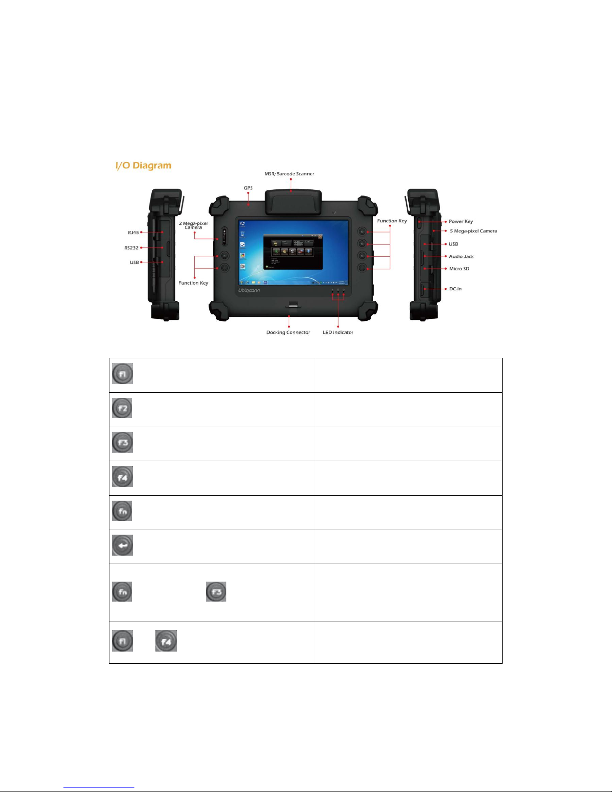
Trigger Buttons (F1 / F4)
Please press F1 or F4 function keys to trigger to scan the barcode when the optional
barcode scanner snap-on module is installed.
If your system does not install this module, these buttons can be programmable to
execute specific software application. When you program your application, please
write this directory as listed below into your configuration file, then the system will
aware and execute this application.
F1_EXE="c:\windows\explorer.exe"
F1_PARA=""
F1_PATH=""
F4_EXE="C:\WINDOWS\system32\taskmgr.exe"
F4_PARA=""
F4_PATH=""
DC-Jack
Lets you connect the AC power adapter in supplying continuous power to your Tablet
PC and recharging the battery.
The AC adapter provides external power source to your system and charges the
internal battery pack at the same time. The AC adapter also has an
auto-switching design that can connect to any 100VAC ~ 240VAC power outlets.
To connect the power adapter:
1. Plug theAC adapter connector to the DC-Jack socket on the left side of the system.
2. Plug the power cord to theAC adapter.
Plug the other end of the power cord to a live wall outlet, at the same time, the
Power LED at front panel lights up.
-- For the power supply of this equipment, an approved power cord has
to be used.
-- Make sure the socket and any extension cord(s) you use can support
the total current load of all the connected devices.
-- Remove all power from the device prior to installing or removing any
accessories, hardware, or cables
-- Before cleaning the system, make sure it is disconnected from
any external power supplies (i.e. AC adapter).
Docking Connector
Lets you connect the system to docking station to dock the tablet PC when you are at
home or office desk.

U
Us
si
in
ng
g
t
th
he
e
H
Ho
ot
tk
ke
ey
y
U
Ut
ti
il
li
it
ty
y
A
Ap
pp
pl
li
ic
ca
at
ti
io
on
n
Your T70C tablet has numbers of applications on the control panel for executing
specific command. It provides you to adjust brightness, volume, launch webcam,
switch monitor (via docking) and RF device ON/OFF.
This user interface provides specific mobile utility to let you easily setup some
helpful functions and aware the system status directly.
This utility also let you adjust some function to fit the requirements, such as
brightness and volume adjustment, webcam launch, monitor switching and RF
device ON/OFF.
Furthermore, it also provides system information for your reference, such as
battery status, RF setting with its signal strength, firmware (BIOS & EC) version
information. Besides these features, you can press the soft button to hibernate
this system.
A
Ab
bo
ou
ut
t
t
th
he
e
U
Us
se
er
r
I
In
nt
te
er
rf
fa
ac
ce
e
Enable or disable the User Interface
To display the User Interface, please press the Fn button or point the Hotkey
Utility icon located on Windows desktop.
To close the User Interface function, please press the Xbutton on the top right
corner on this User Interface for disabling this utility from the screen.
If there is no action within this utility in 5 seconds, the UI screen will close
automatically.
System Status Information
This utility shows you the battery capacity status, RF status with its signal
strength and system information, and provides the control panel for the function
setting.

For battery capacity status:
The
T70C is equipped with one internal battery and one optional external
battery.
The battery capacity status shown below advises you, that only one internal
battery is embedded with the system which is fully charged, and there is no 2nd
optional battery installed in the system.
If the system installs both the 1st internal battery and 2nd optional battery, the
illustration shown below indicates its current charging status and capacity.
If 1st battery capacity drops to 15%, the system will display the following warning
message for 5 seconds.

For RF status:
The following RF status shows you that the system is equipped with Wi-Fi, and
Bluetooth functions. If you want to close either of these functions, please refer
section for how to disable it.
The following signal strength shows you that the Wi-Fi function is connecting
currently, the stronger the signal strength, the more scale will show on the bar. If
there is no module in the system, there will be no status scale in the following
status bar.
For System Information :
The system information shown on the left shows you the hotkey utility version,
BIOS and EC version and you can use them for customer service when asked.

Brightness Control
For brightness adjustment, press the Brightness icon.
When you press it, the brightness control panel is appeared as follows:
You can click or to reduce or increase the LCD brightness.
Also, you can slide the scale bar to set the brightness.
Volume Control
For Volume adjustment, press the Volume icon.
When you press it, the Volume control panel is appeared as follows:
You can click or to reduce or increase the audio volume

incrementally.
Also, you can slide the scale bar to set the audio volume.
You can tick the Mute to mute the audio.
Launch Webcam Utility
For Webcam Launch, press the Webcam icon to launch the Webcam utility.
Or can access the Webcam icon located on desktop.
Monitor Switch
For Monitor switch, press the Monitor Switch to pop-up the selection bar
for choosing the display mode within following four options.
You can click Duplicate to display the same contents both on the
screen and external display device. The resolution on these two display
modes are same, it is not available to adjust the resolution on the external
display mode.
You can click Extend to display the different contents on the
screen and external display device. You only can adjust the resolution on

the external display device.
You can click Projector only to display on external
projector/monitor only.
RF Device ON/OFF Control
Press this soft button (via hotkey utility menu) to enable or disable Wi-Fi, Bluetooth,
WWAN, or GPS devices. When you press the RF ON/OFF soft button, the screen
pops-up the option list for your selection.
You can see all functions in this option list have been ticked. To close any device
function, please touch the option to close the execution as shown in the following
graphics.
Disable Wi-Fi function Disable Bluetooth function
Disable WWAN function Disable GPS function

To activate the function, please again tick the option as shown in the following
graphics to make the device enable.
Activate Wi-Fi function Activate Bluetooth function
Activate WWAN function Activate GPS function
P
Po
ow
we
er
ri
in
ng
g
o
on
n
f
fo
or
r
t
th
he
e
f
fi
ir
rs
st
t
t
ti
im
me
e
The Power/Resume button is found on the left side of the Tablet PC. Press the
Power/Resume button to start your system and check that if the Power LED turns
on.
After a few seconds, the system’s display will turn on and your system will begin
to execute the Power On Self Test or POST to check if all system components are
running properly. Any error found during the test will be displayed on the screen.
After the test, the screen will also display a message "press <F2> to enter SETUP".
You don’t need to run this program at the moment as your dealer already made
the necessary settings for your computer optimal operation.
After the test has completed, your computer will start to search and boot up the
operating system from your hard drive.
Before setting up the system, please make sure the following items are available.
Keyboard
Mouse (for system software installation)

A keyboard is an input device; a mouse is a pointing device. Please connect these two
devices as graphics shown below to interact with your system.
U
Us
si
in
ng
g
t
th
he
e
U
US
SB
B
P
Po
or
rt
ts
s
USB (Universal Serial Bus) is a hardware interface that enables you to connect
multiple devices (such as printers, mice, keyboards, storage devices, joysticks,
digital cameras, and video conference cameras, etc.) to your tablet pc and up to
127 devices can be attached. Besides, USB’s hot swap capability allows
everything to be plugged in and unplugged without turning the system off.
USB 2.0 is fully backward compatible, you will be able to use an USB 1.1 device in
an USB 2.0 compliant system.
1. Connect the external device to the system.
2. The USB ports support hot plug-in connections. Install the device driver before using
the device.
U
Us
si
in
ng
g
t
th
he
e
E
Ex
xt
te
er
rn
na
al
l
A
Au
ud
di
io
o
S
Sy
ys
st
te
em
m
At the right side of your Tablet PC, you will find the headphone jack for
connecting 3.5mm 4-conductor TRRS (stereo-plus-mic) headphone jack.
To connect to a headphone jack:
1. Locate the headphone jack that you want to use to the target device.
2. Plug the jack into the port on the right side of the tablet.

B
Bi
io
os
s
S
Se
et
tu
up
p
P
Pr
ro
og
gr
ra
am
m
This system comes with a chip from Phoenix BIOS that contains the ROM Setup
information for your system. (This chip serves as an interface between the processor
and the rest of the system components.) This section explains the information
contained in the Setup program and tells you how to modify the settings according
to your system configuration.
The Setup utility program allows updates to the main board configuration settings.
The BIOS setup values will be saved in the CMOS. It is executed when you change the
system configuration, you change the system backup battery, or the system detects a
configuration error and asks you to run the Setup program. You must have connected
a USB type of keyboard, and Use the arrow keys to select, and press Enter to run the
selected program.
Function Key
Please check the following table for the function description of each direction key.
Function Key (s)
Function Description
Moves cursor left to select Screens
/
Moves cursor up or down to select items
+ / -
To change option for the selected items
<Tab>
To bring up the selected screen
<F1>
To display the General Help screen
<F10>
To save changes and exit the BIOS
SETUP UTILITY
<ESC>
To jump to the Exit Screen or exit the
current screen
M
Ma
ai
in
n
S
Sc
cr
re
ee
en
n
S
Se
et
tu
up
p
U
Ut
ti
il
li
it
ty
y
When you enter the BIOS SETUP UTILITY, the Main screen will appear and display
the system overview.

The Standard CMOS Setup screen is displayed above. Each feature may have one or
more option settings. Use the arrow keys to highlight the feature you want to change and
then use “”or “”to select the value you want for that feature.
NOTE: The system BIOS automatically detects BIOS, Processor, memory size, thus no
changes are necessary.
NOTE: The system BIOS automatically detects Phoenix, Processor, memory size,
thus no changes are necessary.
System Date
To set the date, highlight the Date field and then press +/- keys to set the current date.
Follow the month, day and year format.
System Time
To set the time, highlight the Time field and then press +/- keys to set the current time.
Follow the hour, minute, and second format.
BIOS Version
The system will automatically displays the information of BIOS version.
Build Time
The system will automatically displays the build time of BIOS.
EC Version
The system will automatically displays the information of EC (Embedded Controller)
firmware version.
VBIOS Version
The system will automatically displays the information of VBIOS version of internal
graphics.
Board Version
The system will automatically displays the information of PCB version of mainboard.
Processor Type
The system will automatically displays the information of Processor Type and speed.
System Memory Speed
The system will automatically displays the information of System Memory Speed.
L2 Cache RAM
The system will automatically displays the information of L2 Cache RAM.

Total Memory
The system will automatically displays the information of Total Memory.
A
Ad
dv
va
an
nc
ce
ed
d
B
BI
IO
OS
S
F
Fe
ea
at
tu
ur
re
es
s
For Advanced Settings, it lets you define the device configuration when system booting.
S
Se
ec
cu
ur
ri
it
ty
y
C
Co
on
nf
fi
ig
gu
ur
ra
at
ti
io
on
n
Set Supervisor Password
This field let you set or clear the Supervisor account’s password.
Set User Password
This field let you set or clear the User account’s password.
TPM Support
Lets you activate or de-activate the TPM function by selecting Enabled or Disabled
option. (For the non-TPM SKU, this item will display “no detected”.)

B
Bo
oo
ot
t
M
Ma
an
na
ag
ge
em
me
en
nt
t
S
Se
et
tu
up
p
This page allows you to set the search drive sequence where the system will try
to boot up first.
To select the boot device, you can use the up or down arrow key, then press <+>
to move up the device in the list or press <-> to move down the device in the list.
To exit from this menu, press <Esc>.
E
Ex
xi
it
t
C
Co
on
nt
tr
ro
ol
l
Exit Saving Changes
When you select this option, it will pop-out the following message, “Save configuration
changes and exit setup?” Select [OK] to save the changes and exit the BIOS SETUP
UTILITY.
Exit Discarding Changes
When you select this option, it will pop-out the following message, “Discard changes
Other manuals for T70C
1
Table of contents
Other Ubiqconn Tablet manuals