User Manual V1.4 Date: 2011.02.18
3.5 Connect the adapter with PC or NB via RS-232 interface.
3.6 If the PC or NB doesn’t equip with the RS-232 DB9 connector, you will need the USB to
RS-232 converter. Please install the driver for the converter installed before the COM port
work.
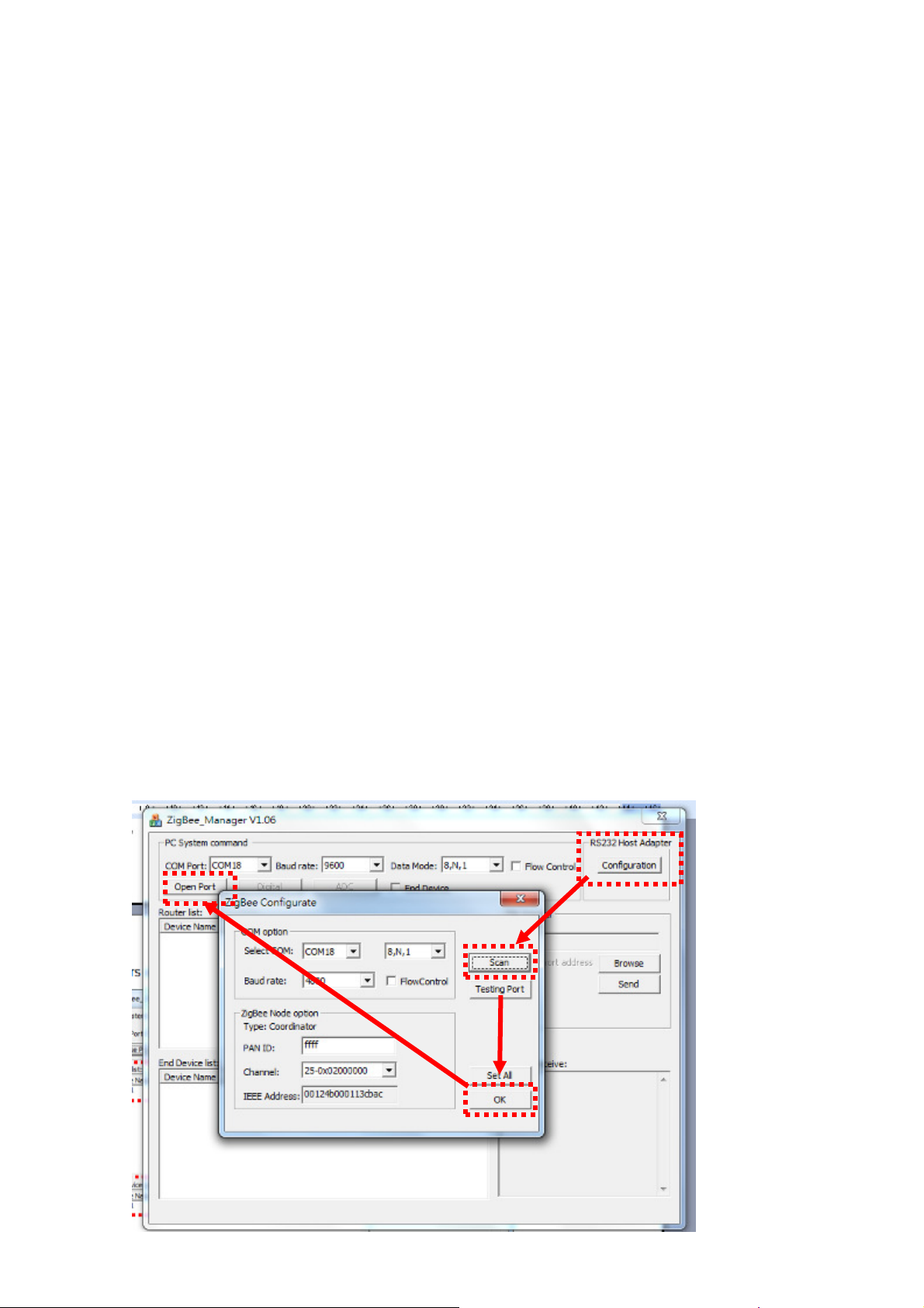
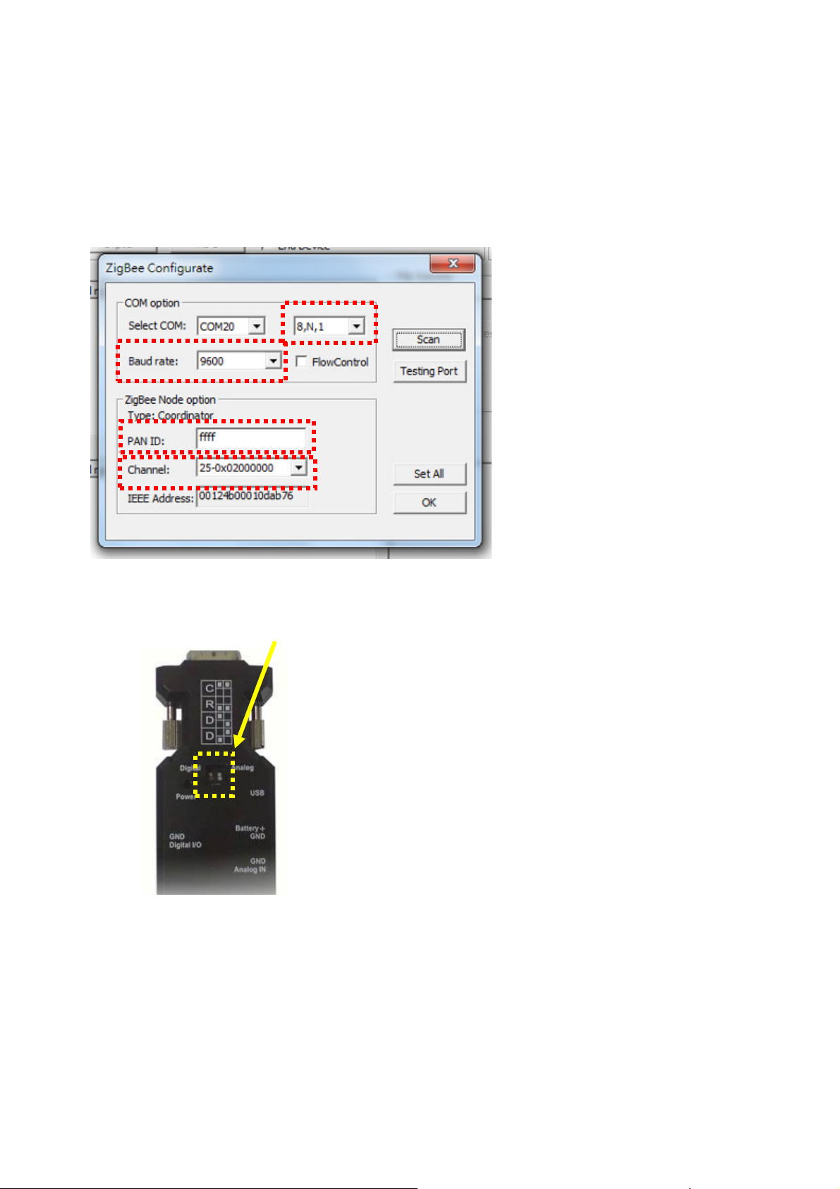
3.7 The coordinator will connect the end device automatically and works for cable replacement
function via RS-232. No software or setting is necessary. If you need to link the mesh network
or router, please check section 7 and 8.
3.8 If the connection is failed, please check the section 9 to recover the default setting.
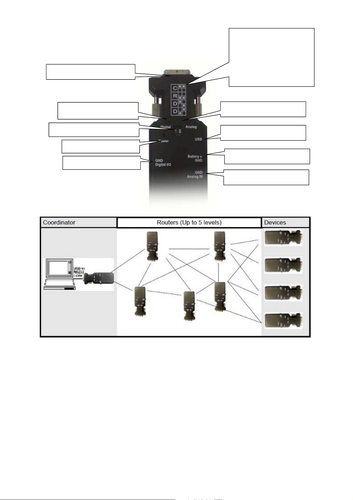
3.9 I/O interface
3.9.1 Digital I/O
Remote control logic high (MIN 2.4V), low (MAX 0.5V).
Output drives capability 20mA.
Max Voltage 3.3V.
3.9.2 Analog Input(ADC)
Max Voltage 3.3V
8bit- resolution
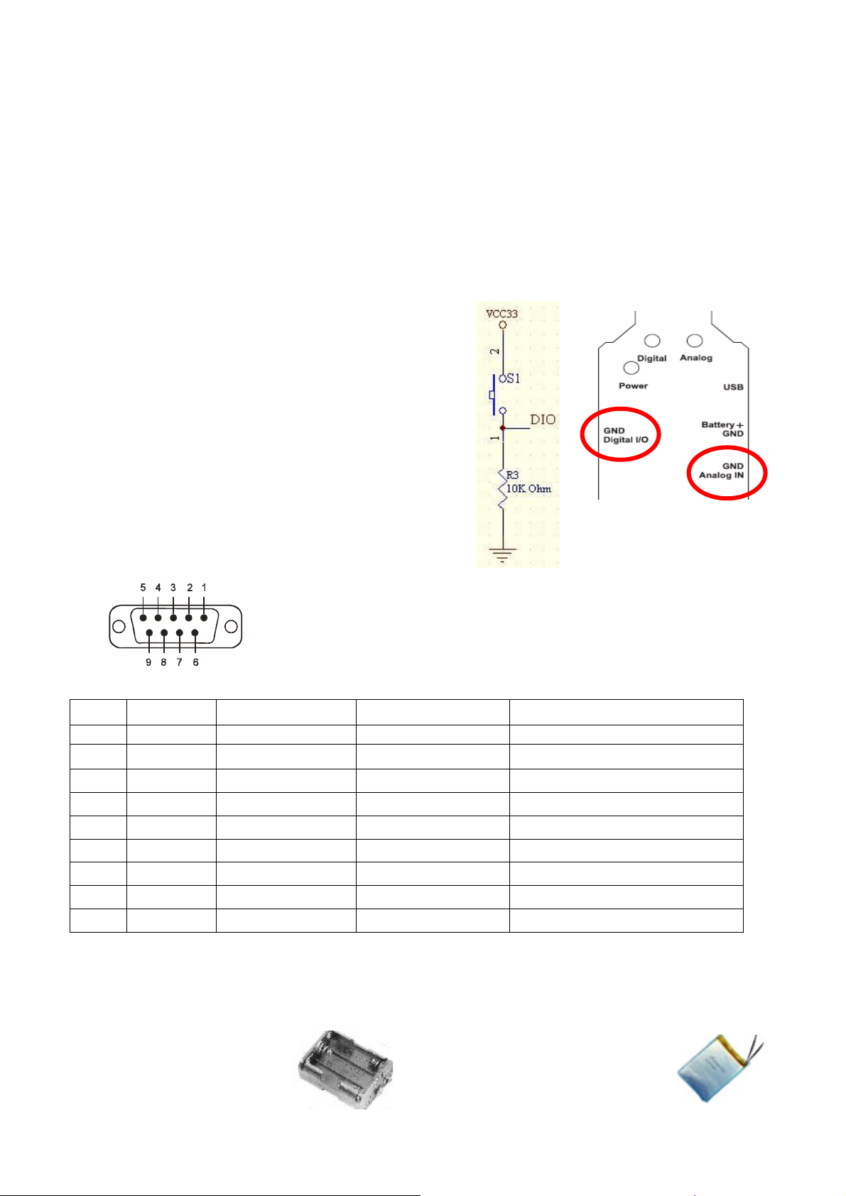
3.10RS-232 DB9 connector
3.8.1 Pin-out:
3.8.2 Signals:
Pin Signal DTE Direction DCE Direction Description
1 CD Input Output Not connected
2 TxD Output Input Transmitted data
3 RxD Input Output Received data
4 DSR Input Output Contact manufacturer to set this
5 GND N/A N/A Signal ground
6 DTR Output Input Contact manufacturer to set this
7 CTS Input Output Clear to send
8 RTS Output Input Request to send (Default)
9 Vcc Input Input Power supply (5VDC, 1.5A Max.)
4 .How to use external battery
4.1 Options:
Standard A, AA or
AAA battery: 3 units for
each model.
Li-Polymer Battery: 3~3.7 VDC.
The capacity depends on the
applications. General working power
consumption: 100 mAh (for
reference)
Digital Input Reference Circuit
(External Switching Function)