Ude AX-459 User manual

450 W. RMS two-input
power amplifier,
for professional audio applications.
-Microprocessor-controlled-
- Output:
- Load impedance:
- Distortion:
- Dimensions:
- Maximun consumption:
- Weight:
- Colour:
- Presentation:
- Passing band:
- Power supply:
- Tone controls:
450 W. RMS at 1 KHz.
11 (L 70 V.).
22 (L 100 V.).
1%.
430x376x140 mm. (3 U).
900 VA.
23.8 Kgs.
Black.
epoxy / metal.
from 50 Hz. to 17 Khz.
230 VAC (50/60 Hz.).
at 100 Hz. 14 dB.
at 10 KHz. 13 dB.
1 balanced microphone input.
1 auxiliary input.
sensitivity=2mV.
impedance = 200 a 600 .
phantom alimentation = 12 VDC.
sensitivity = 770 mV./ 250 mV.
impedance = 47 K .
Signal output.
level = 800 mV
impedance = 600 .
Insertion.
output = 400 mV / 600 .
input = 400 mV / 4700 .
4.
8.
Insertion connector for external signal processors.
8 bits microprocessor.
ON
MOD
OFF
ON
Digital
F
MIC
AUX
4
3
2
1
5
6
7
8
AX-459
151
610.105A
POWER AMPLIFIER DIGITAL
TECHNICAL CHARACTERISTICS
C/ LUIS I, 88, 3ª planta
28031 - MADRID
ESPAÑA
Tel: 34-91 311 60 76
Fax: 34-91 450 19 97
Madrid
Delegation
Main
Office
Avda. BARCELONA, 24
08970 - SANT JOAN DESPÍ
BARCELONA - ESPAÑA
Tel: 34-93 477 28 54
Fax: 34-93 261 17 52
UDE reserves the right to modify the technical characteristics of its products without previous notice

1 2 3 4 5 6
9 8 7
On/off switch
Power indicator
Modulation indicator
Microphone (digital control)
Display
1
2
3
4
5
Bass (digital control)
Treble (digital control)
Microprocessor functions selector
Auxiliary (digital control)
6
7
8
9
Front controls
10 16 17 18
11 12 13 14 15
Data connector (not available) (*2).
Speaker priority line terminal (*5).
Speaker line terminals (*4).
AC input and fuse.
Reset button (*3).
Miicrophone input.
Auxiliary input.
Insertion input/output (*1).
0 dBm signal output.
1611
1510
1712
1813
14
Rear connections
ON
MOD
OFF
ON
Digital
F
MIC
AUX
4
3
2
1
5
6
7
8
AX-459
152
610.105A

Description
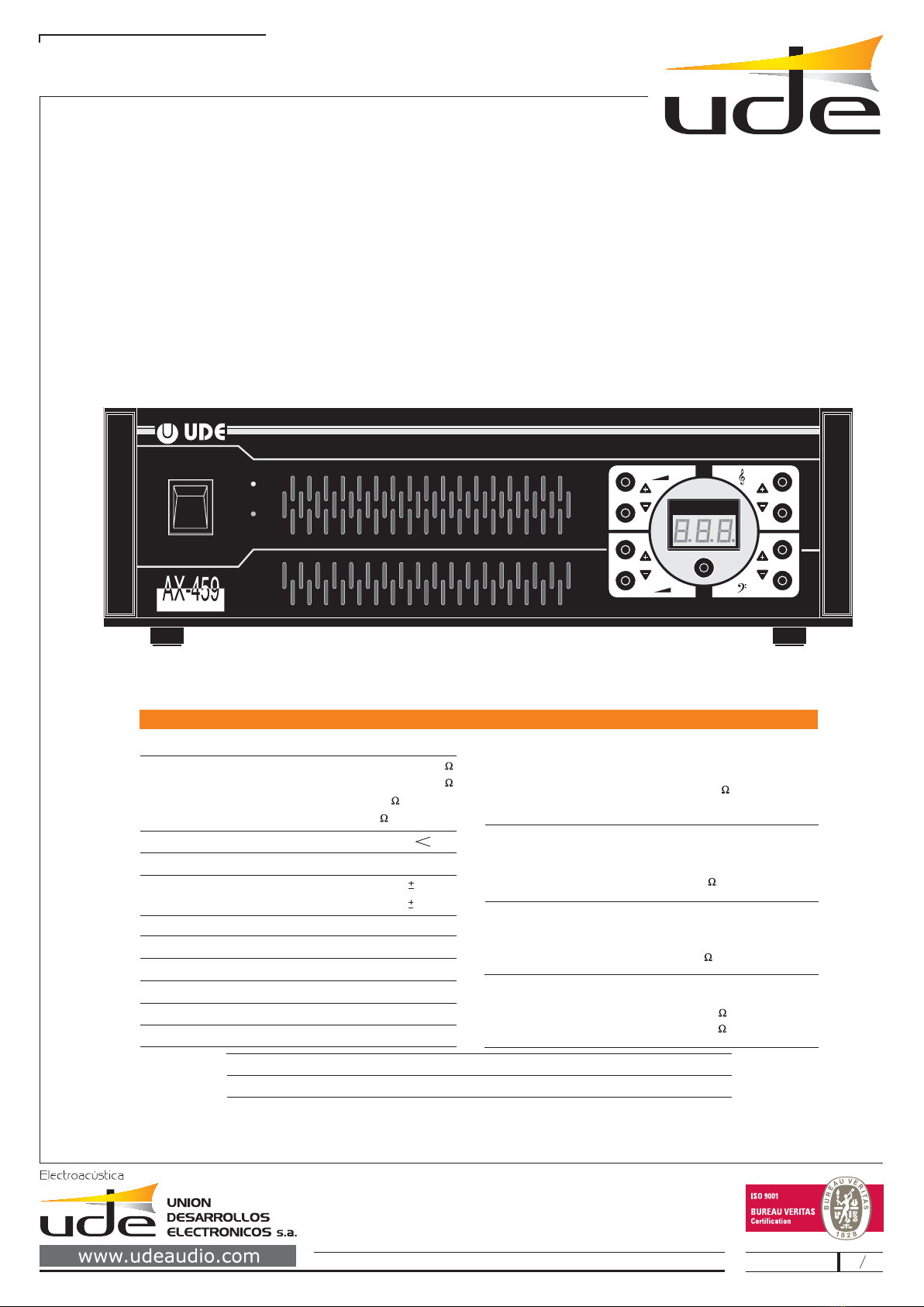
The AX-459 amplifier
The most innovative features of this unit are:
- Controlled power-up
- Automatic and manual adjustment of load impedance.
- Microphone volume control, auxiliary, treble and bass via the keyboard, and which may be
memorised.
- Protection from keyboard tampering
- Forced horizontal air flow system controlled by thermostat at 65 C
AX-459 WX-3
- Display the different statuses of the unit
- Operating mode
AX-459
Mode 1(standard).
Mode 2 (programmed).
includes inside a microprocessor that digitally controls and supervises the main
functions of the apparatus. This particularity, along with the universal signal input system, which can be
configured by the engineer installing the system, make for a reliable, versatile and easy-to use device.
Its mechanical and electronic design are based on the criteria of functionality, toughness and reliability
required in any professional sound application. Its standard sizes (standard 19", 3 U) allow it to be linked to
other elements in the range or others, such as music sources, etc…. making up a homogeneous
compact unit with reasonable space-saving. Its surround housing is protected by a special anticorrosive
treatment.
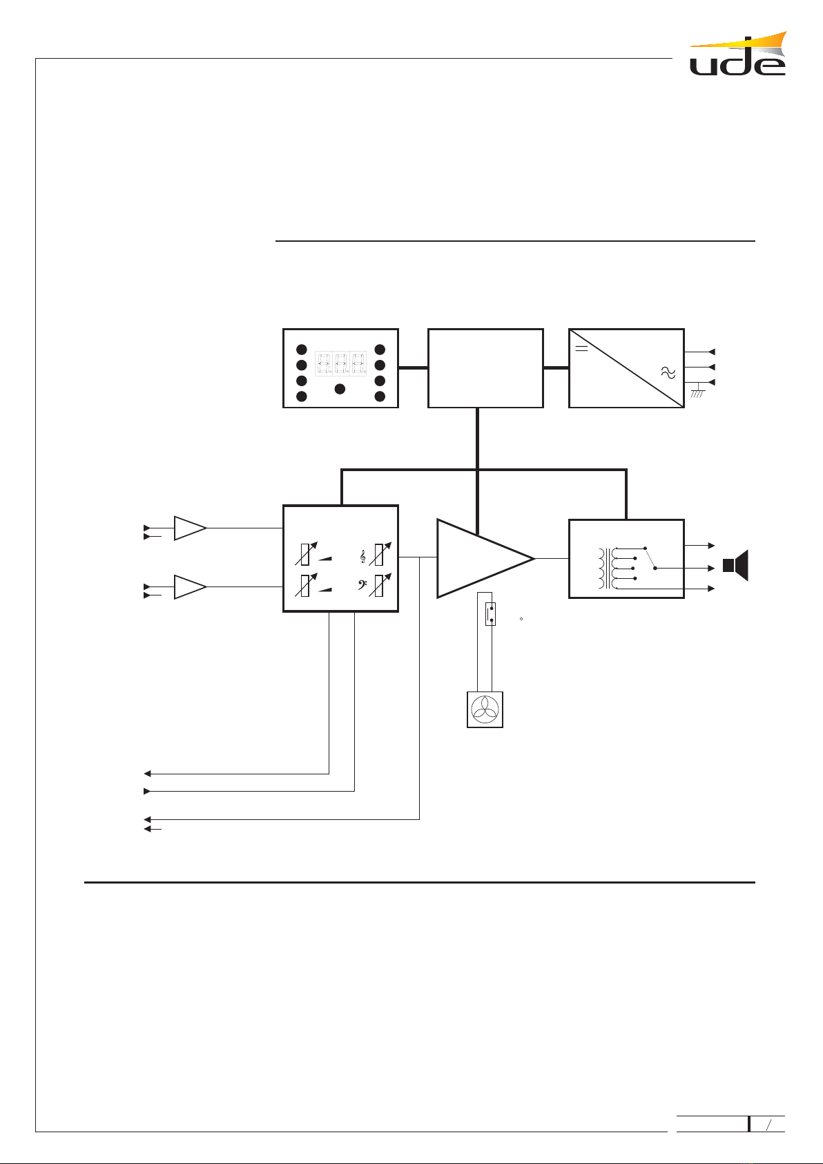
The system limits the power peak absorbed from AC mains which takes place when the amplifier is
powered up. In this way it prevents damage and other trouble, such as the activation of automatic
protection switches or the blowing of fuses in the electrical panel, which are typical in other high-power
units.
The installing engineer may access the load impedance menu and make the adjustments automatically or
else select the right value manually in each case: 4 , 8 , 70 V line (11 ) or 100 V line (22 ).
This function is highly useful, since it makes it possible to record in the non-volatile memory any
adjustments made for different utilisation conditions, thereby optimising the public address system in
applications in fluctuating acoustic conditions. This is mainly due to variations in the size of the audience,
different speakers, background noise in the area, etc.
This function allows the user to select the adjustments later, simply by pressing a button on the keyboard.
Volume can be increased slowly or reduced quickly.
Similarly, the ajustment of microphone volume, treble and bass is totally independent of auxiliary volume,
treble and bass adjustment, which means that on switching from one input to another, either by keyboard
or remote control, the corresponding settings will be maintained.
The installing engineer may program a password to access the installer menu to prevent unwanted
adjustments.
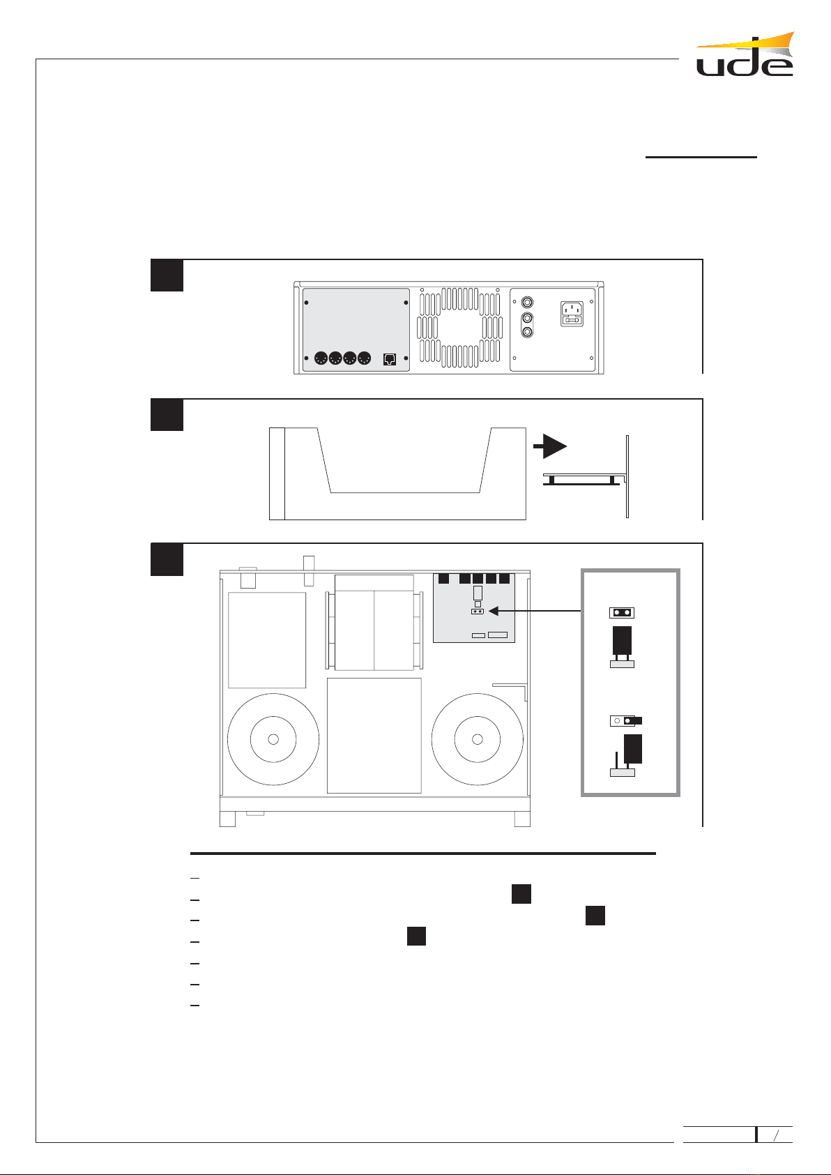
This makes it possible to mount the amplifier on a rack using accessory , with maximum
space optimization.
Luminous display for adjustments, programming, microphone volume level, auxiliary volume level, treble,
bass and messages.
The amplifier can operate in two different modes, as per option.
The user can modify the microphone volume, auxiliary volume, bass and treble of the
amplifier at will.
The user cannot modify the microphone volume, auxiliary volume, treble and
bass of the amplifier set in the installation process.
In this mode the user can select each one of the 8 programmes that are preadjusted in the installation
process.
UDE
AX-459
15
3
610.105A

General characteristics
- Electronic protection against short-circuits in output.
- Power supply suspend.
- Excess temperature (110 C in the power radiator) detector. In the event of overheating caused by a
ventilation obstruction, a safety device will be triggered. When temperature conditions revert to
normal this devise switches off automatically.
- Digital keypad for microphone volume, auxiliary volume, treble and bass.
- Control device for attenuator with maximum level restoration (three wires) incorporated.
- Input 1: balanced microphone, phantom power supply with remote control input (TM1).
- Input 2: auxiliary with remote control input (TM2).
- Signal input/output connection for audio processors (EG-31, etc.)
- Signal output for other amplifiers, with remote-controlled device for attenuators.
- On/off
- Modulation
- Luminous digital display
- 230 VAC at 50/60 Hz
. Antilarsen module.
. Handle / bracket for mounting on 19” rack
. Signal lead
. EG-31 insertion cable.
The amplifier has a plug-in connection jumper which allows the user to change the
sensitivity of the auxiliary input from 770 mV to 250 mV (see graphic).
Indicators:
Power supply:
Optional accessories:
- WX-19
- WX-3
- CA-01
- CA-32
NOTE: AX-459
AX-459
15
4
610.105A

How to start up the unit
INSTALLATION:
Note:
ADJUSTMENTS:
FACTORY SETTINGS:
- Mode 1 operation (standard).
- Access code: 1, 2, 3.
- Impedance: 4
- Auxiliary input sensitivity: 770 mV.
- Input On (selected): microphone (E1).
- MODE 1 (standard)
- MODE 2 (programmed). -
Install the optional accessories (if applicable). See graphic.
Change the sensitivity of the auxiliary input, if applicable. See graphic.
The unit should be connected as per the connection diagram, according to specific
requirements. Special care should be taken to comply with any applicable safety standards.
Do not block the front and rear air vents in order to make sure the unit will work properly.
Start up the unit and make any adjustments you require:
- Impedance
- Volume microphone
- Volume auxiliary
- Treble
- Bass
- Programming (1 to 8)
- Operating mode (standard or programmed) selection
The unit is now ready to operate
.
- Volume: 7.0
- Treble: 0
- Bass: 0
- Volume: 7.0
- Treble: 0
- Bass: 0
The 8 programmes recorded have the same values:
- Volume: 7.0
- Treble: 0
- Bass: 0
- Volume: 7.0
- Treble: 0
- Bass: 0
We recommend you set the volume to 0 for programmes that are not used.
Microphone input (E1)
Auxiliary input (E2)
Microphone input (E1)
Auxiliary input (E2)
AX-459
15
5
610.105A

Change the sensibility of the auxiliary input.
AA
AA
250 mV
770 mV
2
3
1
1
2
3
Remove the top cover of the unit.
Remove the screws (A) from the rear subchassis.
Move the subchassis to expose the signal input/output circuit.
Connect the jumper as required.
Replace the rear subchassis and the 4 screws (A).
Checked that all the connectors fit properly into their respective housings.
Replace the top cover of the unit.
AX-459
15
6
610.105A

MICROPHONE
SOUND SOURCE - Radio, CD, Cassette, etc.
ATTENUATOR - 3-wires maximum level restoration
EG-31 EQUALIZER
PX-9 PRE-AMPLIFIER
230 VAC
MIC
AUX
BASIC
CONNECTION
SYSTEM
WX-19
antilarsen module AUXILIARY AMPLIFIER
CA-01 CA-32
CA-01
Connection diagram
OPTIONAL
ELEMENTS
AX-459
15
7
610.105A

How to assemble the WX-19 module
NOTE: WX-19If you remove the module from the unit you must restore jumper (D)
to its relevant site.
WX-19
D
How to assemble the WX-3
handle / bracket mounting rack
1
2 WX-19
3 WX-19
4
5(D)
6
- Remove the top cover of the unit.
- Remove the bracket for the module.
- Assemble the module in the aforementioned bracket using the screws supplied.
- Fit the 6-lead connection as shown.
- Extract jumper . No special adjustment is needed.
- Fix the bracket in position. The unit is ready to operate.
AX-459
15
8
610.105A

230 VAC
+12 VDC
+5 VDC
15 VDC
450 W RMS
0 dBm OUTPUT
INSERTION
MIC
AUX
TM1
TM2
TM
DIGITAL CONTROL
CONTROL
DIGITAL SIGNAL
±
±92 VDC
AUX
MIC
Th 65 C.
+
P
_
230 VAC
MATCHING
MICROPROCESSOR
Block diagram
AX-459
15
9
610.105A

The installer can use the keyboard and associated display to perform the following
operations:
PASSWORD
SELECTION
1 DIGIT
PASSWORD
2 DIGIT
PASSWORD
3 DIGIT
PASSWORD
INSTALLER
MENU
INSTALLER
MENU
1
2
3
F8
Fig. 1
ACCESS
INSTALLER MENU
INSTALLER MENU
F5
7
ACCEPT
NEW
PASSWORD
4
from nº 1
to nº 8
PASSWORD
SELECTION
CURRENT
PASSWORD
1 DIGIT
OF NEW
PASSWORD
2 DIGIT
OF NEW
PASSWORD
3 DIGIT
OF NEW
PASSWORD
5
6
from nº 1
to nº 8
froml nº 1
to nº 8
F1
Fig. 2
CHANGE
PASSWORD
Access the installer menu .
Change the password in the installer menu .
Select the load impedance of the unit manually (4 , 8 , 70V/16 , 100V/33 ). .
Match load the impedance to the unit automatically .
Change and memorise microphone volume, auxiliary volume, treble and bass settings in the
memory of the standard operation mode for the unit, and restore default values (factory
settings) .
Record programmes .
Copy content from one programme to another .
Edit (correct) an existing programme .
Select the unit’s operating mode (mode 1 / mode 2) .
Return to the user menu .
(Fig. 1)
(Fig. 2)
(Fig. 3)
(Fig. 4)
(Fig. 5)
(Fig. 6)
(Fig. 7)
(Fig. 8)
(Fig. 9)
(Fig. 10)
Press the “F” key and then, while you hold down the
aforementioned key, press key “8”
The display will show “PSD”, whereupon you key in the 3-
figure password.
The factory-set password is “123”
The display will show “123” followed by “INS” (Installer)
If you make a mistake with the password the display will show
“USU” (user) and will revert to the initial status.
The sequence is as follows:
NOTE: If you are unable to access the installer menu because
you cannot remember the password, press the rear reset
button using a suitable object, whereupon “RES” will appear
on the display, and the password is “123”.
ST
ST
nd
nd
rd
rd
AX-459
15
10
610.105A

INSTALLER MENU
4
Fig. 5
MICROPHONE VOLUME
AUXILIARY VOLUME
TREBLE
BASS
INPUTS E1 and E2
ADJUSTMENT
MEMORIZE
VALUES
SELECT
MICROPHONE INPUT (E1) ON
SELECT
AUXILIARY INPUT (E2) ON
RECOVER
VALUES
FROM MEMORY
RECOVER
FACTORY-SET
VALUES
ACTIVE
INPUT
Volume
Value
TREBLE
Treble
Value
BASS
Bass
Value
F1
F2
F3
F4
F5INSTALLER
MENU
VIEW SETTINGS
ACTIVE INPUT
5
6
4
3
7
8
MIN. MIN. MIN.
MAX. MAX. MAX.
VOLUME, TREBLE, BASS,
MICROPHONE INPUT (E1)
ADJUSTMENT
VOLUME, TREBLE, BASS,
AUXILIARY INPUT (E2)
ADJUSTMENT
MIC
4o3
1o2
5
6
2
1
7
8
MIN. MIN. MIN.
MAX. MAX. MAX.
AUX
PUSH SHORT TIME
2MANUAL
ADJUSTMENT
CURRENT
IMPEDANCE
VALUE
NEW
IMPEDANCE
VALUE
INSTALLER
MENU
Z= 4W
Z= 8W
L= 70V
L= 100V
F
F
F
1
2
3
F4
F5
Fig. 3
MANUAL
IMPEDANCE
SELECTION
INSTALLER
MENU
3AUTOMATIC
ADJUSTMENT
CURRENT
IMPEDANCE
VALUE
ADJUSTED
VALUE
4 -8 -70V-100V
WW
F1
F5
Fig. 4
AUTOMATIC
IMPEDANCE
MATCHING
NOTE:
During automatic impedance adjustment one or
several audible tones will be heard through the
loudspeakers.
If the loudspeakers have attenuators, select the
maximum power in the attenuators during
adjustment.
If the attenuators have 3-wire maximum level
restoring the system acts automatically and there is
no need to handle the attenuators
AX-459
15
11
610.105A

5PRESET
PROGRAMME
MENU
CALL UP
PROGRAMME
TO SELECT
RECOVER SETTINGS
RECORDER IN
PROGRAMME nº 2
F2
2
del nº 1
al nº 8
PROGRAMME
SELECTION
INSTALLER
MENU
SETTINGS RECEIVED
FROM PROGRAMME nº 2
RECORDED IN
PROGRAMME nº 3
F1
3
F5
del nº 1
al nº 8
Fig. 7
COPY THE CONTENT OF ONE
PROGRAMME TO ANOTHER
(E.g. copy programme 2 to 3)
Fig. 9
SELECTING OPERATING MODE
STANDARD / PROGRAMMED
INSTALLER
MENU
6OPERATING MODE
MENU
MODE 2
PROGRAMMED
MODE 1
STANDARD
F
F
1
2
F5
INSTALLER MENU
Fig. 10
RETURN TO
USER MENU
8
ACCORDING TO SELECTED
OPERATING MODE
MODE 1
STANDARD
MODE 2
PROGRAMMED
Fig. 8
EDIT (CORRECT) AN
EXISTING PROGRAMME
(E.g. edit programme 7)
5PRESET
PROGRAMME
MENU
CALL UP
PROGRAMME
TO SELECT
RECOVER SETTINGS
RECORDED IN
PROGRAMME 7
F2
7
F5
4
5
6
2
1
7
8
MIN. MIN. MIN.
MAX. MAX. MAX.
AUX
5
6
4
3
7
8
MIN. MIN. MIN.
MAX. MAX. MAX.
CORRECT VALUES
VOLUME, TREBLE, BASS
MICROPHONE INPUT (E1)
CORRECT VALUES
VOLUME, TREBLE, BASS
AUXILIARY INPUT (E2)
MIC
INSTALLER
MENU
ACTIVE
INPUT
E1 or E2
SELECT
MICROPHONE INPUT (E1) ON
SELECT
AUXILIARY INPUT (E2) ON
Volume
Value
TREBLE
Treble
Value
BASS
Bass
Value
F4
1o2
4o3
F5INSTALLER
MENU
VIEW SETTINGS
ACTIVE INPUT
5PRESET
PROGRAMME
MENU
PROGRAMME
SELECTION
ADJUSTMENTS
RECORDED IN
PROGRAMME 7
F1
7
F5
INSTALLER
MENU
5PRESET
PROGRAMME
MENU
PROGRAMME
SELECTION
SETTING
RECORDED IN
PROGRAMME nº 1
F1
1
F5
from nº 1
to nº 8
Fig. 6
RECORDING
PRESET
PROGRAMMES
(fig.5)
PUSH SHORT TIME.
AX-459
15
12
610.105A

Warning messages
POWER SUPPLY
If the amplifier stops working and shows the message, this means that the internal
control device has switched off the unit’s power supply. This may be due to two reasons:
The internal temperature of the unit is too high and the heat protector has been
triggered.
The microprocessor has detected some kind of anomaly in the power supply of the
power circuit, and has switched it off.
Thus, if the message appears, check whether the passage of air (front and rear) is
blocked and put the problem right.
Switch off the amplifier, allow it to cool and then switch it back on again.
Otherwise switch off the unit and call technical assistance.
POWER SUPPLY:
-A.
-B.
AX-459
15
13
610.105A

Use in mode 1 (standard)
USER MENU
Start-up
in mode 1 (standard)
5
6
24
13
7
8
RECOVER MEMORIZED
SETTINGS
INDICATE VOLUME VALUE
MIN. MIN.MIN. MIN. MIN.
MAX. MAX.MAX. MAX. MAX.
START-UP
ON
MOD
OFF
ON
MEMORIZE
VALUES
RECOVER VALUES
MEMORIZED
BY THE USER
INPUT
ACTIVE
E1 or E2
Volume
Value
TREBLE
Treble
Value
BASS
Bass
Value
F1
F2
F4
VIEW SETTINGS
ACTIVE INPUT
AUX MIC
SETTINGS VOLUME, TREBLE, BASS
MICROPHONE INPUT E1
AUXILIARY INPUT E2
SELECT
MICROPHONE INPUT (E1) ON
SELECT
AUXILIARY INPUT (E2) ON
1o2
4o3
It is a good idea to memorise these values(F+1) so that
when the amplifier is switched off and back on again it
will reset with these values.
NOTE:
PUSH SHORT TIME.
Operation
with remote-controlled
message priority
INDICATE
VOLUME VALUE
ISSUE
PRIORITY
MESSAGE
REMOTE-CONTROLLED
TM1 (E1)
MESSAGE PRIORITY
REMOTE-CONTROLLED
TM2 (E2)
MESSAGE PRIORITY
INDICATE
VOLUME VALUE
ISSUE
PRIORITY
MESSAGE
Operating the AX-459 with remote controls TM1 and TM2.
Regardless of which active input is selected (E1 or E2), when TM1 is
pulled E1 becomes the active input, with its corresponding volume,
treble and bass settings. At the same time, the attenuator control
device is activated with 3-wire message priority (terminal P).
Once remote control TM1 is off, the device will revert to its previus
status.
Similarly, if TM2 is pulled input E2 will become the active input with
its corresponding settings, and the priority device is also activated.
During the issue of a priority message all pushbuttons are
deactivated.
If TM1 and TM2 are pulled simultaneously, TM2 will be given priority.
AX-459
15
14
610.105A

Use in mode 2 (programmed)
USER MENU
Start-up
in mode 2 (programmed)
START-UP IS ALWAYS
WITH PROGRAMME 1
ACTIVE
INPUT
E1 or E2
Volume
Value
TREBLE
Treble
Value
BASS
Bass
Value
SELECTED
PROGRAMME
F4
PROGRAMME
1
PROGRAMME
2
PROGRAMME
3
PROGRAMME
4
PROGRAMME
5
PROGRAMME
6
PROGRAMME
7
PROGRAMME
8
1
2
3
4
5
6
7
8
START-UP
ON
MOD
OFF
ON
PROGRAMME SELECTION
VIEW VALUES OF
SELECTED PROGRAMME
Operation
with remote-controlled
message priority
CURRENT
PROGRAMME
ISSUE
PRIORITY
MESSAGE
REMOTE-CONTROLLED
TM1 (E1)
MESSAGE PRIORITY
REMOTE-CONTROLLED
TM2 (E2)
MESSAGE PRIORITY
CURRENT
PROGRAMME
ISSUE
PRIORITY
MESSAGE
Operating the AX-459 with remote controls TM1 and TM2.
Regardless of which active input is selected (E1 or E2), when TM1 is
pulled E1 becomes the active input, with its corresponding volume,
treble and bass settings. At the same time, the attenuator control
device is activated with 3-wire message priority (terminal P).
Once remote control TM1 is off, the device will revert to its previus
status.
Similarly, if TM2 is pulled input E2 will become the active input with
its corresponding settings, and the priority device is also activated.
During the issue of a priority message all pushbuttons are
deactivated.
If TM1 and TM2 are pulled simultaneously, TM2 will be given priority.
AX-459
15
15
610.105A
Table of contents
Other Ude Amplifier manuals