UFO 150 CDMX+G-DCT User manual

UFO LIGHTING
FIBER OPTIC &LED LIGHTING SYSTEMS
REVISION: B1
UFO COMPACT 150W DMX+UNIVERSAL ILLUMINATOR
PLEASE READ THIS USER GUIDE BEFORE INSTALLING, CONNECTING
OR OPERATING THIS ILLUMINATOR.
USER GUIDE
MODELS COVERED:
UFO 150 CDMX+G-DCT / UFO 150 CDMX+G-DCT
UFO 150 CDMX+G-DC / UFO 150 CDMX+G-CT
UFO 150 CDMX+G-C / UFO 150 CDMX+G-D
UFO 150 CDMX+P-DCT / UFO 150 CDMX+P-DC
UFO 150 CDMX+P-CT / UFO 150 CDMX+P-C
UFO 150 CDMX+P-D / UFO 70 CDMX+G-DCT
UFO 70 CDMX+G-DC / UFO 70 CDMX+G-CT
UFO 70 CDMX+G-C / UFO 70 CDMX+G-D
UFO 70 CDMX+P-DCT / UFO 70 CDMX+P-DC
UFO 70 CDMX+P-CT / UFO 70 CDMX+P-C
UFO 70 CDMX+P-D

INTRODUCTION
Thank you for purchasin this UFO illuminator
Please read these instructions fully before connectin your unit to the electrical supply, and
keep them for future reference.
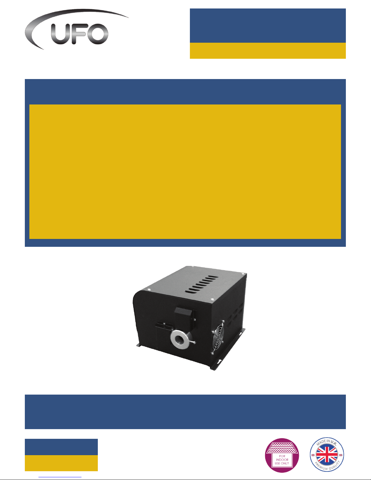
A hi h performance 70W or 150W metal halide illuminator for ultimate bri htness which can be
fitted with up to three decorative wheels as follows:
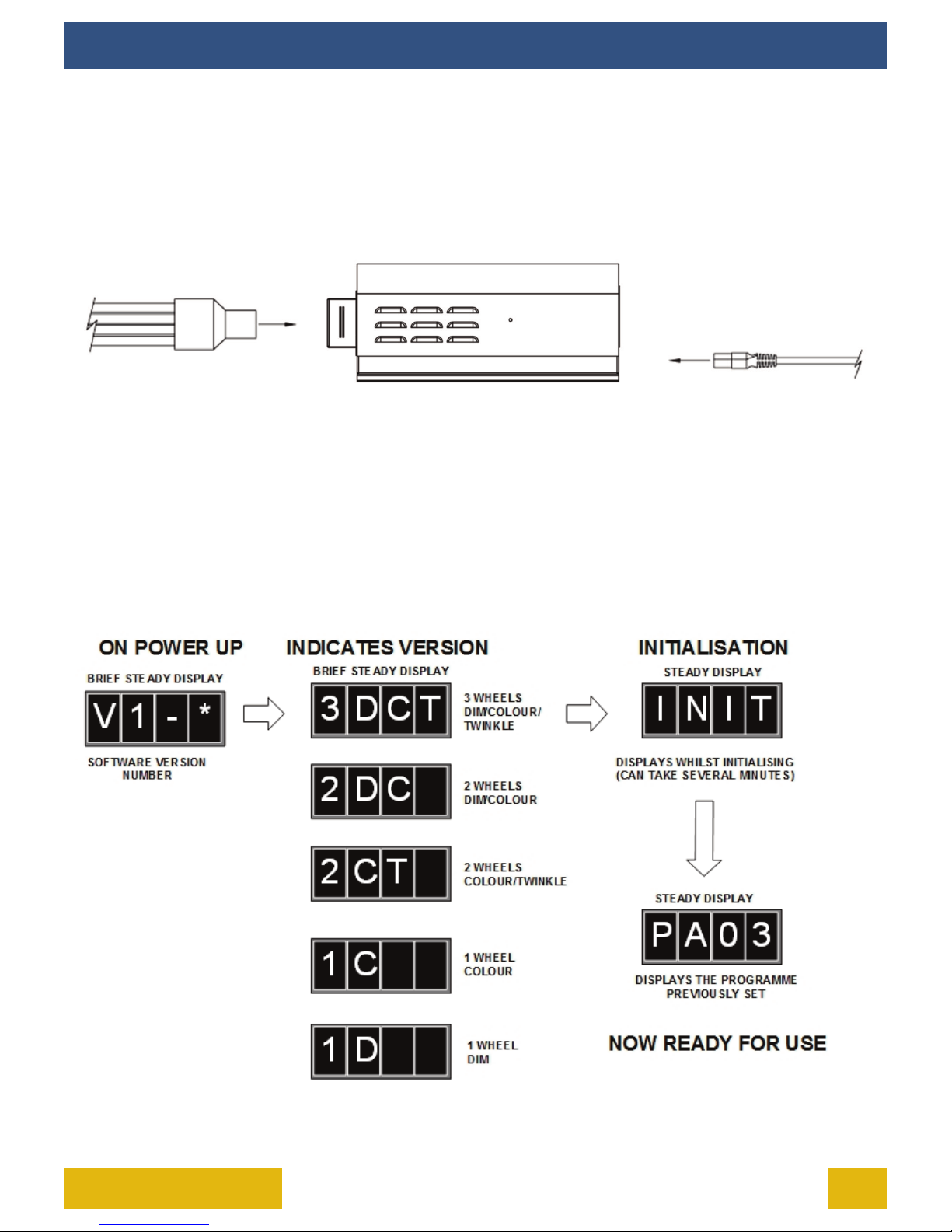
3DCT – Dimmin , Color and Twinkle
2DC – Dimmin and Color
2CT – Color and Twinkle
1C – Colou only
1D – Dimmin only
We do not recommend that the illuminator be le on for 24 hours a day, 7 days a
week as lamp life will be impaired. A switch off of 30mins per day is recommended.
2150W UNIVERSAL DMX+USER GUIDE
IMPORTANT
WARNING – To reduce the risk of FIRE, ELECTRIC SHOCK OR INJURY TO PERSONS:
1. Unplu and allow to cool before replacin lamp.
2. Always disconnect the unit from the power supply before openin or attemptin
to perform any work on it.
3. Do not touch hot lens, uard, or enclosure.
4. Do not look directly at li hted lamp.
5. Use only with the correct lamp watta e as detailed on the serial label.
6. Do not touch the lamp at any time. Use a so cloth. Oil from skin may dama e lamp.
7. Do not operate product with missin or dama ed uard, lamp containment barrier,
lens or fiber optic harness.
8. Contact UFO for replacement lamp uard, lamp containment barrier, lens or fiber
optic harness
9. Lamp types are matched to the ballast and different watta es/types cannot be
used.
10. Ensure that the power supply is correct for the unit before powerin it up.
11. Always ensure that the unit is properly earthed.
12. Do not expose the unit to rain or moisture.
13. Never attempt to tamper with the wirin or other internal components.
14. Keep the unit away from as, oil and any other flammable or explosive materials.

3UFO LIGHTING
IMPORTANT SAFETY INFORMATION
THIS PRODUCT MUST BE INSTALLED IN ACCORDANCE WITH THE APPLICABLE
INSTALLATION CODE BY A PERSON FAMILIAR WITH THE CONSTRUCTION AND
OPERATION OF THE PRODUCT AND THE HAZARDS INVOLVED.
Do not operate without complete lamp enclosure in place or if lens is dama ed.
KEEP HARNESS IN PLACE WHEN IN OPERATION.
CAUTION: Hot surface. Keep away from curtains and other combustible materials.
WARNING: RISK OF FIRE/INJURY TO PERSONS. Keep away from combustibles. Unplu
to chan e lamp. Do not touch lamp.
WARNING: RISK OF FIRE. Do not place lamp where the overhead surface is closer than
0.3m to the illuminator.
TYPE Y ATTACHMENT: If the external flexible cable or cord of this luminaire or
associated PSU/driver is dama ed. It shall be exclusively replaced by the manufacturer
or his service a ent or a similar qualified person to avoid a hazard.
LOCATION: Do not locate this luminaire closer than 300mm from any flammable
surface.
CLEARANCE/VENTILATION: It is imperative that a ap of 300mm is le around the unit.
This is to allow air to circulate and prevent overheatin . The location must have free
ventilation and must not have a ambient temperature hi her than that specified for
the luminaire.
MOUNTING: This is a fixed luminaire. See separate mountin instructions for fixin to
surface.
WARNING: Never look directly into the luminaire illuminator.

ILLUMINATOR LAYOUT
4
Item Descripon
1 DMX connect on Sockets
2 LED d splay and control buttons
3 Power LED
4 Ma ns power nput
5 Lamp holder
6 Cool ng fan
7 Motor Covers
8 F ber port
9 4 x Access screws
10 4 x Mount ng holes
150W UNIVERSAL DMX+USER GUIDE

5UFO LIGHTING
INSTALLATION
In order for the DMX+ illuminator to function safely and efficiently it must be installed
accordin to this user manual. Please read all sections thorou hly before switchin on
the illuminator.
POWER SUPPLY REQUIREMENTS
Before plu in in the unit, please make sure that the supply is correct. Failure to do so could
cause the unit to malfunction. The unit requires a 240VAC 50Hz supply and it MUST BE EARTHED.
The illuminator units are provided with a cordset fitted with a standard plu . UNIT MUST NOT BE
DIMMED.
POSITIONING THE UNIT
The illuminator can be mounted horizontally, vertically or upside-down on any flat surface.
Keyhole slots are provided on the base of the unit to allow for securin to a surface. The illumina-
tor is only suitable for use in a dry area.
If the unit is bein mounted at a hi her than the round level, block access below the work area
before installin .
Verify that any screws or bolts can safely bear the wei ht of the illuminator.

INSTALLATION
6
Verify that the supportin structure can safely bear the wei ht of all installed units, cables and any
other equipment.
For horizontal mountin , it is recommended that the illuminator is secured to a solid surface usin
4 x M4 or M5 screws or bolts and the keyhole slots. This is particularly important if the illuminator
location is not at round floor level.
To mount the illuminator vertically, first securely install 4 x M4 or M5 screws or bolts at the
required distances so that they will line up with the keyhole slots. The illuminator can then be
mounted onto them and slid into position. The bolts or screws MUST then be fully ti htened.
To mount the illuminator under a surface, first securely install 4 x M4 or M5 screws or bolts at the
required distances so that they will line up with the keyhole slots. The illuminator can then be
mounted onto them and slid into position. The bolts or screws MUST then be fully ti htened.
CLEARANCE / VENTILATION
It is imperative that a ap of 300mm or more is le around the unit. This is to allow air to circulate
and prevent overheatin . The location must have free ventilation.
150W UNIVERSAL DMX+USER GUIDE

7UFO LIGHTING
INSTALLATION
CONNECTION
There are 2 main connections required - the fiber port and the mains power supply. Connect and
secure the fiber optic connector to the fiber port before connectin the electrical supply. Never run
the illuminator with the fiber connector unplu ed. For separate feed units, there will be
additional power connections required.
OPERATION
Aer installin and connectin the illuminator as described above, all you have to do is turn the
power on. The lamp will take 3-4 minutes to reach full bri htness. This is normal for this type of il-
luminator.
Durin the power up sequence the soware version number and the model version is displayed
momentarily as detailed below:
If no li ht is produced, please consult the TROUBLESHOOTING section in this manual.

OPERATION
8
REAR PANEL CONTROLS
NOTE:
1. The le hand display module shows a rotatin ‘X’ when DMX data is present.
2. The microphone (under the display) for sound to li ht applications is a fully functional device,
but is not implemented in the soware. This application is a special feature on request.
150W UNIVERSAL DMX+USER GUIDE

9UFO LIGHTING
OPERATION
REAR PANEL CONNECTORS
1. DMX OUT - standard 3-pin DMX output connector
2. DMX IN - standard 3-pin DMX input connector
3. AC IN - standard fused IEC power connector
4. DATA OUT - RJ45 connection to UFO RIU (remote indicator unit)
The DMX wirin connections are detailed below:
Like all data networks the DMX cable should be terminated on the DMX out of the last illumina-
tor usin a terminator plu .

OPERATION
10
The DMX+ llum nator has two modes of operat on - standalone and DMX.
STANDALONE MODE
In standalone mode, the Compact DMX+ can be used in two ways - either as a sin le independent
illuminator or in master/slave confi uration with several illuminators connected to ether usin
DMX cables.
In master/slave confi uration all addresses are set the same and whatever pro ram is selected on
the master unit will also be executed on the slave units.
DMX MODE
Li ht sources set in DMX mode can either be controlled by another Compact DMX+ in master
mode, or by a standalone DMX controller.
PROGRAMMING THE ILLUMINATOR
The DMX+ can be pro rammed for various functions and modes from the rear panel controls as
shown on the followin pa es.
RESET VIA DMX
When resettin via DMX (Channel 1 - 128-191) care must be taken to ensure channels 2 to 5 are first
set to 0 value.
Failure to do this will result in the illuminator ‘freezin ’. If a illuminator freezes in this way it can be
reverted to normal by cyclin the mains power off and then on a ain.
150W UNIVERSAL DMX+USER GUIDE

11UFO LIGHTING
OPERATION
PROGRAMMING THE DMX+

OPERATION
12
PROGRAMMING THE DMX+
150W UNIVERSAL DMX+USER GUIDE

13UFO LIGHTING
DMX CHANNEL INFORMATION
NOTE
1. *See Reset note on pa e 9
2. DMX will always take 5 channels. Where channels are not used in certain versions they will remain, but be inactive
3. Colors 1-9 shown represent standard colors
4. Channel 5 adjusts the “snap” speed between colors
Unit numbers: (1) All model versions / (2) models 3DCT, 2DC, 1D / (3) models 3DCT, 2DC, 2CT, 1C / (4) models 3DCT, 2CT
Ch Funcon Func
No. Value Effect Units
01 Reset and lamp/fans power 01 0-127 Normal and lamp on 1
01 Reset and lamp/fans power 02 128-191 Reset f held for 5 seconds * 1
01 Reset and lamp/fans power 03 192-250 Normal and lamp on 1
01 Reset and lamp/fans power 04 251-255 Lamp o f held for 10 seconds 1
02 D mmer wheel control 01 0-255 0=fully closed / 255=fully open 2
03 Color wheel var able 0-90 01 0 Clear/wh te 3
03 Color wheel var able 0-90 02 10 Color 1 (blue) 3
03 Color wheel var able 0-90 03 20 Color 2 (green) 3
03 Color wheel var able 0-90 04 30 Color 3 (yellow) 3
03 Color wheel var able 0-90 05 40 Color 4 (red) 3
03 Color wheel var able 0-90 06 50 Color 5 (p nk) 3
03 Color wheel var able 0-90 07 60 Color 6 (orange) 3
03 Color wheel var able 0-90 08 70 Color 7 (v olet) 3
03 Color wheel var able 0-90 09 80 Color 8 (magenta) 3
03 Color wheel var able 0-90 10 90 Color 9 (apr cot) 3
03 Color wheel snap 91-170 11 91-98 Color 9 3
03 Color wheel snap 91-170 12 99-106 Color 8 3
03 Color wheel control snap to color 91-170 13 107-114 Color 7 3
03 Color wheel control snap to color 91-170 14 115-122 Color 6 3
03 Color wheel control snap to color 91-170 15 123-130 Color 5 3
03 Color wheel control snap to color 91-170 16 131-138 Color 4 3
03 Color wheel control snap to color 91-170 17 139-146 Color 3 3
03 Color wheel control snap to color 91-170 18 147-154 Color 2 3
03 Color wheel control snap to color 91-170 19 155-162 Color 1 3
03 Color wheel control snap to color 91-170 20 163-170 Clear/wh te 3
03 Color wheel speed clockw se 21 171-212 Fast to slow 3
03 Color wheel speed counter-clockw se 22 213-255 Slow to fast 3
04 Tw nkle wheel control 01 0-14 Stop/open 3
04 Tw nkle wheel control clockw se 02 15-126 Slow to fast 4
04 Tw nkle wheel control 03 127-144 Stop/open 4
04 Tw nkle wheel control counter-clockw se 04 145-255 Fast to slow 4
05 Color wheel d splay durat on 01 0-255 Short to long durat on 3

STANDALONE/MASTER PROGRAMMABLE FUNCTIONS
14
Prog Funcon Unit
PA01 Color 9, no tw nkle 1
PA02 Color 8, no tw nkle 1
PA03 Color 7, no tw nkle 1
PA04 Color 6, no tw nkle 1
PA05 Color 5, no tw nkle 1
PA06 Color 4, no tw nkle 1
PA07 Color 3, no tw nkle 1
PA08 Color 2, no tw nkle 1
PA09 Color 1, no tw nkle 1
PA10 Color 0, no tw nkle 1
SA01 Color 9, tw nkle 2
SA02 Color 8, tw nkle 2
SA03 Color 7, tw nkle 2
SA04 Color 6, tw nkle 2
SA05 Color 5, tw nkle 2
SA06 Color 4, tw nkle 2
SA07 Color 3, tw nkle 2
SA08 Color 2, tw nkle 2
SA09 Color 1, tw nkle 2
SA10 Color 0, tw nkle 2
PB01 Color change 0-9, no tw nkle 1
PB02 Color change 1-9, no tw nkle 1
PB03 Color change 2-9, no tw nkle 1
PB04 Color change 3-9, no tw nkle 1
PB05 Color change 4-9, no tw nkle 1
PB06 Color change 5-9, no tw nkle 1
PB07 Color change 6-9, no tw nkle 1
PB08 Color change 7-9, no tw nkle 1
PB09 Color change 8-9, no tw nkle 1
PB10 Color change 2-6, no tw nkle 1
SB01 Color change 0-9, slow tw nkle 2
SB02 Color change 1-9, slow tw nkle 2
SB03 Color change 2-9, faster tw nkle 2
SB04 Color change 3-9 ,faster tw nkle 2
SB05 Color change 4-9, fastest tw nkle 2
SB06 Color change 5-9, fastest tw nkle 2
SB07 Color change 6-9, fastest tw nkle 2
SB08 Color change 7-9, slower tw nkle 2
SB09 Color change 8-9 ,slower tw nkle 2
SB10 Color change 2-6, slowest tw nkle 2
Prog Funcon Unit
PC01 Snap color change 0-9, no tw nkle 1
PC02 Snap color change 1-9, no tw nkle 1
PC03 Snap color change 2-9, no tw nkle 1
PC04 Snap color change 3-9, no tw nkle 1
PC05 Snap color change 4-9, no tw nkle 1
PC06 Snap color change 5-9, no tw nkle 1
PC07 Snap color change 6-9, no tw nkle 1
PC08 Snap color change 7-9, no tw nkle 1
PC09 Snap color change 8-9, no tw nkle 1
PC10 Snap color change 2-6, no tw nkle 1
SC01 Snap color change 0-9, slow tw nkle 2
SC02 Snap color change 1-9, slow tw nkle 2
SC03 Snap color change 2-9, faster tw nkle 2
SC04 Snap color change 3-9, faster tw nkle 2
SC05 Snap color change 4-9, fastest tw nkle 2
SC06 Snap color change 5-9, fastest tw nkle 2
SC07 Snap color change 6-9, faster tw nkle 2
SC08 Snap color change 7-9, slower tw nkle 2
SC09 Snap color change 8-9, slower tw nkle 2
SC10 Snap color change 2-6, slowest tw nkle 2
PD01 Color rotate CCW slowest no tw nkle 1
PD02 Color rotate CCW slow no tw nkle 1
PD03 Color rotate CCW slow no tw nkle 1
PD04 Color rotate CCW faster no tw nkle 1
PD05 Color rotate CCW fastest no tw nkle 1
PD06 Color rotate CCW fastest no tw nkle 1
PD07 Color rotate CCW faster no tw nkle 1
PD08 Color rotate CCW slow no tw nkle 1
PD09 Color rotate CCW slow no tw nkle 1
PD10 Color rotate CCW slowest no tw nkle 1
SD01 Color rotate tw nkle speed 1 ccw 2
SD02 Color rotate tw nkle speed 2 ccw 2
SD03 Color rotate tw nkle speed 3 ccw 2
SD04 Color rotate tw nkle speed 4 ccw 2
SD05 Color rotate tw nkle speed 5 ccw 2
SD06 Color rotate tw nkle speed 5 cw 2
SD07 Color rotate tw nkle speed 4 cw 2
SD08 Color rotate tw nkle speed 3 cw 2
SD09 Color rotate tw nkle speed 2 cw 2
SD10 Color rotate tw nkle speed 5 cw 2
CCW - counter clockw se from front of un t / CW - clockw se from font of un t
Un t numbers: (1) models 3DCT, 2DC, 2CT, 1C / (2) models 3DCT, 2DC, 2CT
150W UNIVERSAL DMX+USER GUIDE

15UFO LIGHTING
MAINTENANCE
CLEANING THE UNIT
Disconnect unit from power supply and allow to cool before attemptin any cleanin of the unit.
A visual check of the unit should be completed every 12 months. However cleanin should
take place as and when required.
The body of the unit can be cleaned with a so, damp cloth - do not use any abrasives on the unit.
The fans and vents should be kept clear by periodically blowin them out with compressed air.
Glass filter to be cleaned with soap and water then dried.
Date Maintenance Undertaken
MAINTENANCE LOG
Please note that a record of all maintenance MUST be kept in the table below, indicatin what
maintenance was undertaken and when. This must be dated for warranty purposes..

MAINTENENACE
16
LAMP REPLACEMENT
A lamp replacement every 12 months is recommended for metal halide illuminators.
1) Unplu unit from electrical supply and allow to cool.
2) On the rear of the unit, unscrew the two knurled
securin nuts (A) which hold the lamp holder in
position.
3) Use the handle (B) to withdraw the lampholder from
the illuminator.
4) Unplu the old lamp from its ceramic holder.
5) Plu the new lamp into the holder, makin sure that
you use a lamp of the same specification as to that
which was removed. Also make sure not to touch the
lass part of the lamp.
6) Slide the lamp holder plate back into position
carefully – makin sure the lamp drawer runners line up
internally on the lampholder slides. Push the drawer
home firmly and ti hten the two retainin nuts.
NOTE: If the lamp does not strike aer replacement
check to see if the fans are runnin . If the lamp is not
strikin and the fans are not runnin , the lampholder
drawer is not properly inserted.
150W UNIVERSAL DMX+USER GUIDE

17UFO LIGHTING
MAINTENANCE
FUSE REPLACEMENT
1) Unplu unit from electrical supply and allow to cool.
2) The fuse is located in a drawer under the mains input
connector. There is also a spare fuse located in this
drawer.
3) Open the fuse drawer.
4) Withdraw fuse from its holder
5) Replace with identically specified fuse - see
specification table in this manual.
6) Close the fuse drawer and power up the illuminator.

TROUBLESHOOTING
18 150W UNIVERSAL DMX+USER GUIDE
Probable Cause Remed
Lamp has fa led Replace lamp
Lamp st ll warm aer power cycle, not
restr k ng Wa t unt l lamp str kes
Ballast c rcu t faulty Check ballast c rcu t and replace faulty parts
or contact UFO for ass stance
Probable Cause Remed
Fan has fa led or s fa l ng Replace fan
Un t overheat ng - too hot an env ronment Vent late or move to cooler env ronment
Probable Cause Remed
Color wheel magnet fallen o or not be ng
sensed by sensor PCB, due to too w de a gap
or sensor cable plug d slodged
Glue magnet back on wheel n correct place
Check magnet sensor al gnment
Check sensor cable plugged n to ma n PCB
correctly

19UFO LIGHTING
TROUBLESHOOTING
Probable Cause Remed
Tw nkle wheel magnet fallen o or not be ng
sensed by sensor PCB, due to too w de a gap
or sensor cable plug d slodged
Glue magnet back on wheel n correct place
Check magnet sensor al gnment
Check sensor cable plugged n to ma n PCB
correctly
Probable Cause Remed
D mmer wheel magnet fallen o or not be ng
sensed by sensor PCB, due to too w de a gap
or sensor cable plug d slodged
Glue magnet back on wheel n correct place
Check magnet sensor al gnment
Check sensor cable plugged n to ma n PCB
correctly

TROUBLESHOOTING
20 150W UNIVERSAL DMX+USER GUIDE
Problem Probable cause(s) Remed
Un t s completely dead - Lamp
and neon power nd cator are
not llum nated
Ma n fuse blown Check and replace fuse
No power ro un t Check that power s sw tched on and psu s
plugged n
LED power nd cator & fan are
on, but no l ght s output
Lamp blown Replace lamp
Thermal sw tch act vated Allow un t to cool for 5 to 10 m nutes and
nvest gate reason for overheat ng
Lamp w res are not
connected
Check plug connect on - ensure lamp s properly
seated n ts holder and the p ns are fully mated
Poor l ght output
Lamp needs replac ng Replace lamp
Un t needs clean ng Clean reflector and glass lens
Incorrect power supply Ensure power supply s 240VAC 50Hz
F ber port connector not
plugged n correctly
Ensure f ber port connector s plugged n
correctly, and that the screw s t ghtened up
properly
Lamp go ng on & o randomly Un t s overheat ng Allow un t to cool for 5 to 10 m nutes and
nvest gate reason for overheat ng
Lamp not str k ng & both fans
not runn ng
Lamp holder drawer on rear of
un t not pushed n fully
Remove lamp holder drawer and re nsert,
ensur ng fully pushed h me and t ghtened up
Un t resets correctly but does
not respond to controller
The controller s not connected Connect the controller
Reversed data s gnal polar ty Install a phase revers ng cable between the un t
and the controller
Bad data l nk connect on Check cables and connect ons. Repa r or replace
damaged cables.
Data l nk not term nated Insert term nat on plug nto output of the last
un t n the l nk
Incorrect address sett ng Check address sett ng
One of the un ts s transm tt ng
as a master or s faulty
Bypass one f xture at a t me unt l normal
operat on s rega ned
Un t does not reset correctly An eect requ res mechan cal
adjustment Contact UFO for ass stance
No l ght output Lamp too hot to str ke Allow lamp to cool
Faulty lamp Check and replace lamp
Lamp cuts out nterm ttently or
burns out too qu ckly
Un t s too hot Allow un t to cool
Faulty fan Contact UFO for ass stance
Un t freezes dur ng DMX reset Reset not correctly carr ed out Recycle ma ns power o and on
This manual suits for next models
19
Table of contents
Other UFO Dj Equipment manuals