UFO GEMINI Series User manual

UFO LIGHTING
FIBRE OPTIC &LED LIGHTING SYSTEMS
REVISION: B1
GEMINI SLIMLINE LIGHT SOURCE
USER GUIDE
PLEASE READ THIS USER GUIDE BEFORE INSTALLING, OPERATING OR
PERFORMING MAINTENANCE ON THE LIGHT SOURCE UNIT

INTRODUCTION
Thank you for purchas ng th s UFO l ght source.
To ensure that the l ght source s set up opt mally and g ves a long serv ce l fe, please read th s
user gu de before nstall ng, operat ng or perform ng any ma ntenance on the un t.
Please keep th s user gu de for future reference.
Th s l ght source s su table for ndoor use only unless t s s tuated n a weatherproof enclosure.
MODELS COVERED BY THIS USER GUIDE
UFO GEM SLP-3000M / UFO GEM SLP-4000M
UFO GEM SLP-3000DMX / UFO GEM SLP-4000DMX
UFO GEM SLP-300010V / UFO GEM SLP-400010V
IMPORTANT
Th s product must be nstalled n accordance w th the appl cable nstallat on code, by a person
fam l ar w th the construct on and operat on of the product, and the hazards nvolved.
These l ght sources are not ma ns d mmable.
The LED array n th s l ght source s not replaceable. When t reaches end of l fe the whole un t
must be replaced.
Type Y Attachme t: If the external flex ble cable or cord of th s lum na re or assoc ated
PSU/dr ver s damaged. It shall be exclus vely replaced by the manufacturer or h s serv ce agent
or a s m lar qual f ed person to avo d a hazard.
Locatio : Do not locate th s l ght source closer than 200mm from any flammable surface.
Cleara ce / Ve tilatio : It s mperat ve that a gap of 200mm s le around the un t. Th s s to
allow a r to c rculate and prevent overheat ng. The locat on must have free vent lat on and must
not have an amb ent temperature h gher than that spec f ed for the lum na re.
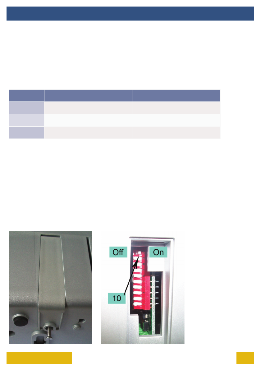
Mou ti g: Th s s a f xed lum na re. See mount ng plate nstruct on on Page 3 for
f x ng to surface.
War i g: Never look d rectly nto the lum na re LED l ght source.
War i g: The lum na re should be pos t oned so that prolonged star ng nto the
lum na re at a d stance closer than 0.33m s not expected.
GEMINI USER GUIDE2

3UFO LIGHTING
INSTALLATION
ATTACH THE LIGHT SOURCE TO ITS MOUNTING PLATE
F t the metal mount ng plate to the base of the l ght source before mak ng electr cal
connect ons.
Remove the mount ng plate and the four plast c 2 part (screw and r vet body) from the box.
Invert the l ght source and remove the four rubber feet. Separate the screws from the r vet
bod es and push f t the r vet bod es nto the holes vacated by the feet.
Al gn the plate aga nst the r vets and secure the plate to the l ght source w th the four plast c
screws us ng an M4 poz -dr ve screwdr ver. Do not overt ghten. The l ght source can now be
f xed securely to the mount ng surface.
Note: Mount ng plate d agram s nd cat ve only.

INSTALLATION
The l ght source s powered from a desktop 12V DC power supply un t.
The power supply un t s an IEC nput dev ce and caters for UK/European/other ma ns suppl es
us ng the relevant power cord.
POWER SUPPLY REQUIREMENTS
There are 2 connect ons requ red – the f bre port and the ma ns supply cable. The f bre port
should be connected f rst. Connect and secure the f bre opt c connector nto the collar and
secure us ng the M5 lock ng screw.
Connect the PSU to the DC nput jack socket on the l ght source, and connect the IEC cable to
the PSU. Plug the ma ns plug nto the electr cal supply socket. Sw tch on power the led
nd cator w ll llum nate and the l ght source s ready for use. If no l ght s produced consult the
TROUBLESHOOTING sect on of th s user gu de.
Note that these l ght sources are not ma ns d mmable.
CONNECTION - GEMINI M MODELS ONLY
GEM SLP-XXXXM CONNECTIONS GEM SLP-XXXXDMX / 10V CONNECTIONS
GEMINI USER GUIDE4

There are 3 connect ons requ red – the f bre port, the ma ns supply cable and the DMX control
cable(s). The f bre port should be connected f rst. Connect and secure the f bre opt c connector
nto the collar and secure us ng the M5 lock ng screw.
Connect the PSU to the DC nput jack socket on the l ght source, and connect the IEC cable to
the PSU. Plug the ma ns plug nto the electr cal supply socket. Sw tch on power the led
nd cator w ll llum nate and the l ght source s ready for use. If no l ght s produced consult the
TROUBLESHOOTING sect on of th s user gu de.
Connect the DMX control cable(s) to the M n -XLR sockets on the rear of the l ght source. The
recommended plug for these sockets s Mult comp SVP556-TA. The p n out deta ls for the plugs
are shown below. E ther socket may be used as DMX n or DMX out.
CONNECTION - GEMINI DMX MODELS ONLY
Note: UFO can supply converters for these l ght sources to allow them to be nterfaced to
standard 3 p n XLR connectors or RJ45 connectors.
INSTALLATION
5UFO LIGHTING

INSTALLATION
GEMINI USER GUIDE6
Th s s external current source d mm ng - the l ght source d mm ng nput requ res an
external 0-10V source.
There are three connect ons requ red - the f bre port, the ma ns supply cable and the 0-10V
control cable(s). The f bre port should be connected f rst. Connect and secure the f bre opt c
connector nto the collar and secure us ng the M5 lock ng screw.
Connect the PSU to the DC nput jack socket on the l ght source, and connect the IEC cable to
the PSU. Plug the ma ns plug nto the electr cal supply socket. Sw tch on power the led
nd cator w ll llum nate and the l ght source s ready for use. If no l ght s produced consult the
TROUBLESHOOTING sect on of th s user gu de.
THE LIGHT SOURCE WILL NOT ILLUMINATE UNLESS DIP SWITCH 10 IS ON AND A 0-10V
SIGNAL IS PRESENT
Connect up the 0-10V control cable(s) to the m n XLR sockets on the rear of the l ght source.
The recommended plug for these sockets s the Mult comp SVP556-TA. The p n out deta ls for
these plugs are shown below. E ther socket may be used as 0-10V IN or 0-10V OUT
CONNECTION - GEMINI 0-10V MODELS ONLY
Note: UFO can supply converters for these l ght sources to allow them to be nterfaced to
standard 3 p n XLR connectors or RJ45 connectors.

7UFO LIGHTING
OPERATION
USING THE LIGHT SOURCE - GEMINI M MODELS ONLY
Under normal operat on the Gem n M l ght source can be d mmed manually us ng the d mmer
control on the rear of the un t.
USING THE LIGHT SOURCE - GEMINI DMX MODELS ONLY
Gem n DMX l ght sources can be d mmed remotely, can be sw tched on/o and can be
addressed manually.
Channel Funcon Value Descripon
1 Dimmin 0-255 From off at 0 to bri ht at 255
2 LED & Fan 0-250 LED and fan on
2 LED & Fan 251-255 LED and fan off
Unless the address s spec f ed on the purchase order, all l ght sources w ll be defaulted to
address 001. Connect the DMX controller to e ther of the M n XLR sockets, and the l ght source
can now be d mmed. Add t onal slave (wh ch are set to the same address) DMX l ght sources can
be l nked together.
1. D sconnect the l ght source from the ma ns supply.
2. T lt the l ght source on ts s de and remove the screw from the base as shown below.
3. Sl de the access cover down to remove and set the cover and screw as de.
4. Sw tch DIP sw tch 10 (top) to ON as shown below.
5. Replace access cover and secur ng screw.
REVERTING A DMX LIGHT SOURCE TO MANUAL OPERATION MODE

OPERATION
GEMINI USER GUIDE8
1. D sconnect the l ght source from the ma ns supply.
2. T lt the l ght source on ts s de and remove the screw from the base as shown below.
3. Sl de the access cover down to remove and set the cover and screw as de.
4. Ensure DIP sw tch 10 (top) s set to OFF as shown below.
5. Set the address requ red as deta led n the address table, overleaf.
6. Replace access cover and secur ng screw,
SETTING THE DMX ADDRESS
Note: for DMX control
operat on to work, d p
sw tch 10 must be n the
o pos t on.
See the table and d agram on the follow ng page for nstruct ons on sett ng the DMX address
us ng d p sw tches.

9UFO LIGHTING
OPERATION
SETTING THE DMX ADDRESS
DMX B Start
Channel # Dip Switches On DMX B Start
Channel # Dip Switches On
1 1 11 1,2,4
2 2 12 3,4
3 1,2 13 1,3,4
4 3 14 2,3,4
5 1,3 15 1,2,3,4
6 2,3 16 5
7 1,2,3 : :
8 4 : :
9 1,4 : ;
10 2,4 511 1,2,3,4,5,6,7,8,9
Note: w th d p sw tch 10 OFF, the l ght source w ll not llum nate unless a DMX s gnal s present.

OPERATION
GEMINI USER GUIDE10
USING THE LIGHT SOURCE - GEMINI 0-10V MODELS ONLY
Gem n 0-10V models allow the l ght output to be var ed by apply ng a d erent voltage through
the rear connectors. The follow ng table represents l ght output percentage aga nst approx mate
control value nput.
Li ht Output
Percenta e Volta e
100% 7 - 10V
90% 6.2V
80% 5.8V
70% 5.4V
60% 5V
50% 4.5V
40% 3.9V
30% 3.2V
20% 2.3V
10% 1.4V
5% 1.1V
2.5% 0.8V
1.25% 0.4V
0% 0.2V
Note: the l ght source w ll not llum nate
unless d p sw tch 10 s on and a 0-10V
control voltage s n place.

11UFO LIGHTING
MAINTENANCE
MAINTENANCE LOG
Date Maintenance Undertaken
Note: a record of all ma ntenance MUST be kept n the table above, nd cat ng what ma ntenance
was undertaken and when. Th s MUST be dated for warranty purposes.

TROUBLESHOOTING
GEMINI USER GUIDE12
PROCEDURES FOR ALL MODEL TYPES
Problem Possible Cause(s) Remedy
Unit is dead –
no li ht output
and LED power
indicator on
PSU is not
illuminated
Mains supply off Check supply & reinstate
Loose mains plu s Check plu s
Plu fuse blown (UK) Check fuse. If blown, replace
PSU failed Replace PSU
Unit is dead –
no li ht output
and LED power
indicator on
PSU is illumi-
nated, but LED
indicator on
Li ht source not
illuminated
PSU failed Replace PSU
Unit is dead –
no li ht output
but LED power
indicator is
illuminated
DMX dimmin at minimum
(for DMX version only)
Adjust bri htness on
controller (increase value up
from 0)
DMX fault on controller or
DMX cable
Remove DMX XLR plu from rear of li ht
source. Li ht source wil default to full
bri ht. Repair DMX controller
or cablin .
LED array failure Replace li ht source
Unit not
respondin to
DMX
commands
Address incorrect Check the address set on unit matches
the address set on the controller
DMX cable fault
Refer to manual dia ram for correct
wirin terminaon. Carry out connuity
check.
Swap DMX cable for known
ood cable
Note: please complete relevant troubleshoot ng procedures before return ng the un t to us for
further nvest gat on.

13UFO LIGHTING
TROUBLESHOOTING
Problem Possible Cause(s) Remedy
0-10V Version
unit is dead -
no li ht output -
but LED
indicator on
li ht source is
illuminated.
No 0-10V dimmin to unit
(0V = LED Off)
Refer to manual dia ram for
correct terminaon.
Carry out connuity check.
Carry out volta e / polarity
0-10V cable fault check
0-10V cable fault
Controller fault
Carry out volta e / polarity
check at controller.
Repair / replace as necessary
0-10V LED PCB failure Replace 0-10V PCB
No 0-10V si nal
present
Controller off or failed Check controller. Ensure 0-
10V si nal present
0-10V cable faulty
Carry out volta e and
polarity check on mini XLR
plu . Repair as necessary
ADDITIONAL PROCEDURES FOR 0-10V MODELS ONLY
Note: please complete relevant troubleshoot ng procedures before return ng the un t to us for
further nvest gat on.

TECHNICAL SPECIFICATIONS
GEMINI USER GUIDE14
Descripon Details
Port connector size 30mm diameter
Fibre type Glass / PMMA
Mains Supply Volta e 100-240V AC, 50-60Hz
PSU Output 12V DC, 5A, 60W max.
LED Power 20W
Min Ambient Temperature -10°C
Max Ambient Temperature +45°C
Fan 60mm crossflow, 12V
Led Type White li ht
Funconality [model specific]
Manual models - dimmin
DMX models - dimmin , switch on/off
0-10V models - dimmin
DMX [specific models only] User addressable 1 channel dimmin and 1 channel
on/off control
0-10V [specific models only] 0-10V DC receivin
LED Life 50,000 hours typical
CRI >93 (typical)
Colour Temperature 3000°K or 4000°K
Material ABS
Finish Grey
Dimensions (L x W x H) / Wei ht 222mm x 114mm x 81mm / 900

15UFO LIGHTING
NOTES

DESIGN SPECIFY BUILD INSTALL
Un ted K ngdom •Un ted States •Germany •Europe •UAE
Un versal F bre Opt cs Ltd
Home Place
Coldstream, TD12 4DT
Un ted K ngdom
t. +44 (0)1890 883416
www.ufo.l ght ng
Un versal F ber Opt c L ght ng USA LLC
1749 Northgate Blvd,
Sarasota, FL34234
USA
t. +1 941-343-8115
www.f beropt cl ght ng.com
Made n the Un ted K ngdom
UFO L cht GmBH
Raum 2.38, Fr endsfactory AG,
Gutenbergstraße 1,
Munchen 85737, Deutschland
t. +49-(0)9491-95588-0
www.ufo-l cht.de
This manual suits for next models
6
Table of contents
Other UFO Dj Equipment manuals
Popular Dj Equipment manuals by other brands

Chauvet DJ
Chauvet DJ FREEDOM CENTERPIECE Quick reference guide

Beamz
Beamz Snow900 instruction manual

Lightmaxx
Lightmaxx Vector Haze 1.0 user manual

Alesis
Alesis GigaMix 8FX Service manual

EuroLite
EuroLite DS-10 operating instructions

Larson Electronics
Larson Electronics BLG-LED-4REX-GRN instruction manual