Ugolini BT 18/7 User manual

BT 18/7
MANUALE D’ISTRUZIONI
OPERATOR’S MANUAL

BT18/7
DICHIARAZIONE DI CONFORMITÀ CE
Noi Ugolini S.p.A. - Via dei Pioppi 33 - 20090 Opera Milano - Italy dichiariamo, sotto la nostra responsabilità, che i prodotti
BT18/7 - 230V 50Hz sono conformi alle seguenti Normative:
In ottemperanza alle Direttive EC 73/23, EC 98/37, EC 89/336.
EC DECLARATION OF CONFORMITY
We Ugolini S.p.A. - Via dei Pioppi 33 - 20090 Opera Milano - Italy declare, under our responsability, that the products
BT18/7 - 230V 50Hz are in conformity with the following Standards:
Following the provisions of the DirectivesEC 73/23, EC 98/37, EC 89/336.
DECLARATION DE CONFORMITE CE
Nous Ugolini S.p.A. - Via dei Pioppi 33 - 20090 Opera Milano - Italy déclarons, sous notre responsabilité, que les produits
BT18/7 - 230V 50Hz sont conformes aux Normes suivantes:
Conformément aux Directives EC 73/23, EC 98/37, EC 89/336.
EG-ÜBEREINSTIMMUNGSERKLÄRUNG
Wir Ugolini S.p.A. - Via dei Pioppi 33 - 20090 Opera Milano - Italy erklären auf eigene Verantwortung, daß die Produkte
BT18/7 - 230V 50Hz mit den folgenden Normen übereinstimmen:
Gemäß den EWG-Richtlinien EC 73/23, EC 98/37, EC 89/336.
DECLARACIÓN DE CONFORMIDAD CE
Nosotros Ugolini S.p.A. -ViadeiPioppi 33 - 20090 OperaMilano - Italy declararamos, bajo nuestra responsabilidad, que
los productos BT18/7 - 230V 50Hz responden con las siguientes Normativas:
En cumplimiento de las Normas EC 73/23, EC 98/37, EC 89/336.
-
-
-
-
-
EN 292 Part 1 1991
EN 292 Part 2 1991
EN 60335-1 1995
EN 60335-2-75 1994
DIN VDE 700 Teil 240 1983, mod. A1 1988
-
-
-
-
EN 60555-2 1994
EN 60555-3 1986
EN 61000-3-2 1986
EN 61000-3-3 1994
-
-
-
-
-
EN 292 Part 1 1991
EN 292 Part 2 1991
EN 60335-1 1995
EN 60335-2-75 1994
DIN VDE 700 Teil 240 1983, mod. A1 1988
-
-
-
-
EN 60555-2 1994
EN 60555-3 1986
EN 61000-3-2 1986
EN 61000-3-3 1994
-
-
-
-
-
EN 292 Part 1 1991
EN 292 Part 2 1991
EN 60335-1 1995
EN 60335-2-75 1994
DIN VDE 700 Teil 240 1983, mod. A1 1988
-
-
-
-
EN 60555-2 1994
EN 60555-3 1986
EN 61000-3-2 1986
EN 61000-3-3 1994
-
-
-
-
-
EN 292 Part 1 1991
EN 292 Part 2 1991
EN 60335-1 1995
EN 60335-2-75 1994
DIN VDE 700 Teil 240 1983, mod. A1 1988
-
-
-
-
EN 60555-2 1994
EN 60555-3 1986
EN 61000-3-2 1986
EN 61000-3-3 1994
-
-
-
-
-
EN 292 Part 1 1991
EN 292 Part 2 1991
EN 60335-1 1995
EN 60335-2-75 1994
DIN VDE 700 Teil 240 1983, mod. A1 1988
-
-
-
-
EN 60555-2 1994
EN 60555-3 1986
EN 61000-3-2 1986
EN 61000-3-3 1994
vedere targa dati sulla macchina
see data plate on the machine
voir la plaque sur l’appareil
siehe Dispenser Typenschild
ver la placa del distribuidor Ugolini S.p.A.
L’Amministratore Delegato
(luogo ed anno di prod. - place and mfr. year - lieu et an de production
Produktionsort und Produktionsjahr - lugar y año de producción)

GARANZIA
3
1. L’apparecchio è garantito per un periodo di dodici mesi dalla
data di acquisto. Tale data viene certificata dalla ricevuta e/o fat-
tura fiscale e/o da un documento di consegna rilasciato dal Riven-
ditore.
2. Per garanzia si intende la sostituzione o riparazione gratuita
delle parti componenti l’apparecchio riconosciute difettose all’ori-
gine, per vizi di fabbricazione.
3. Non sono coperte dalla garanzia le parti aventi funzione este-
tica e tutte le parti che dovessero risultare difettose a causa di ne-
gligenza o trascuratezza nell’uso, di errata installazione o
manutenzione, di manutenzioni operate da personale non autoriz-
zato, di trasporto senzadovute cautele,di circostanze che comun-
que non possano farsi risalire a difetti di fabbricazione
dell’apparecchio.
Sono altresì esclusi dalle prestazioni in garanzia gli interventi tec-
nici inerenti l’installazione e l’allacciamento agli impianti di alimen-
tazione elettrica e idrica.
4. La casa costruttrice declina ogni responsabilità per eventuali
danni che possano, direttamente o indirettamente, derivare a per-
sone o cose in conseguenza della mancata osservanza di tutte le
prescrizioni indicate nelle apposite “Istruzioni”, concernenti in par-
ticolare le avvertenze in tema di installazione,uso emanutenzione
dell’apparecchio.
5. Nel caso di apparecchi per i quali sia previsto l’intervento a
domicilio, l’acquirente è tenuto a corrispondere il diritto fisso di
chiamata in vigore presso il fabbricante alla data dell’intervento.
Qualora l’apparecchio venga riparato presso uno dei laboratori
autorizzati dal fabbricante, le spese ed i rischi di trasporto relativi
saranno a carico dell’acquirente.
6. Trascorsi dodici mesi dall’acquisto decade il dirittodi garanzia
e l’assistenza verrà esplicata addebitando, oltre alle spese di ma-
nodopera, anche il costo delle parti sostituite e quello di trasporto.
7. Sono esclusi la sostituzione dell’apparecchio ed il prolunga-
mento della garanzia a seguito di intervenuto guasto.
8. E’ escluso dalla garanzia l’apparecchio la cui targa di identifi-
cazione risulti manomessa, asportata o comunque in condizioni
tali da non rendere possibile l’identificazione certa dell’apparec-
chio stesso.
9. Tale garanzia è valida solo in Italia.
4
7

BT18/7
4
1 CARATTERISTICHE TECNI-
CHE
E’ riservato il diritto di modifica senza preavviso.
2 INTRODUZIONE
Congratulazioni per aver acquistato il nostro di-
stributore d'acqua calda e fredda modello BT 18/
7.
Sebbene sia un apparecchio sofisticato il vostro
nuovo distributore BT 18/7 è estremamente sem-
plice da usare grazie alle numerose funzioni au-
tomatiche.
Il distributore ha un sistema di scorrimento del
bottiglione su guide che agevola il rifornimento
dell'acqua senza sforzo.
I bottiglioni d'acqua sono installati con il collo ver-
so l'alto e privi del sigillo di garanzia; quando l'ap-
parecchio è in funzione, il collo del bottiglione
viene automaticamente sigillato per prevenire
ogni contaminazione dall'esterno.
BT 18/7 raffredda l'acqua attraverso un'unità di
refrigerazione a semiconduttore che non danneg-
gia l'ambiente.
Quando il bottiglione è vuoto, si accende un Led
luminoso e un avvisatore acustico suona una me-
lodia.
Il serbatoio per l'acqua calda è in acciaio inossi-
dabile e studiato senza punti di saldatura.
Per poter utilizzare al meglio le potenzialità del
vostro distributore, vi ricordiamo di leggere que-
sto manuale con attenzione e di conservarlo in un
posto sicuro per successive consultazioni.
Come tutti i prodotti meccanici, anche questo di-
stributore richiede pulizia e cura.
3 INSTALLAZIONE
3. 1 PER UN FUNZIONAMENTO
SICURO
1Verificare che all’inteno della scatola vi
sia il libretto di istruzione e la garanzia.
2Mantenere una adeguata distanza tra il
muro e il retro della BT18/7, almeno 15 cm.
3Non esporre il BT18/7 a fonti dirette di
calore. Posizionarlo in una stanza con una
BT 18/7
Dimensioni:
larghezza cm 340
profondità cm 398
altezza cm 1021
Peso netto, circa kg 22
Serbatoio acqua calda l 2
Serbatoio acqua fredda l 2
Termostato regolabile 1
Livello di rumorosità inferiore a 70 dB (A)
IMPORTANTE
Caratteristiche elettriche: leggere i dati
riportati sulla targa di ogni singolo distribu-
tore. I dati riportati sulla targa sono sempre
quelli a cui fare riferimento.

5
escursione termica massima tra 32°C e 0°C, per
un funzionamento ottimale.
3. 2 ISTRUZIONI PER L’USO
1Controllare se lo sportello di carico si apre e
chiude facilmente.
2Dopo aver inserito la spina in una presa a
220V dedicata, accendere l'interruttore generale
posto sul pannello posteriore. Due "beep" avver-
tiranno della presenza di tensione al distributore.
3A sportello aperto, dopo 5 minuti, una melo-
dia avvertirà di richiuderlo.
4Estrarre il carrello del distributore, rimuovere
il sigillo di plastica del bottiglione, sistemarlo
esattamente al centro del carrello e spingerlo
dentro richiudendo poi lo sportello.
5In seguito il "tubo d'aspirazione" scende e la
"pompa" inizia a fornire acqua ai serbatoi del
freddo e del caldo.
6Accendere l'interruttore "Hot water switch"
posto sul pannello posteriore; ricordarsi di spe-
gnere questo interruttore quando non si richiede
acqua calda.
7Sono necessari 20 minuti per riscaldare e 45
minuti per raffreddare l'acqua raggiungendo così
le impostazioni iniziali.
NOTA:
La melodia suona anche con il portello chiuso,
quando il bottiglione è vuoto.
4 SOSTITUZIONE DEL BOTTI-
GLIONE
1Quando il bottiglione d'acqua è vuoto, il Led
"empty" comincia a lampeggiare e parte una
melodia.
2Aprire lo sportello, aspettare alcuni secondi
finché il "tubo aspiratore" sale completamente e
trascinare fuori dal distributore il carrello.

BT18/7
6
3Togliere il bottiglione vuoto e sistemarne uno
nuovo da 19 litri nel centro del carrello.Reinse-
rirlo poi nel distributore, chiudendo lo sportello.
5 CONTROLLO DELLA TEMPE-
RATURA
5. 1 ACQUA CALDA
L'acqua nel serbatoio del caldo è riscaldata con
una resistenza (band type) pari a 480W.
Un sensore della temperatura controllato dal mi-
croprocessore è posizionato nel serbatoio dell'ac-
qua calda e previene il rischio di
surriscaldamento. La temperatura raggiunta è cir-
ca 90-92°C.
Nota:Ricordarsi di spegnere l'interruttore dell'ac-
qua calda quando non è richiesta
5. 2 ACQUA FREDDA
l'acqua nel serbatoio dell'acqua fredda è raffred-
data da una unità refrigerante a semiconduttori.
La temperatura dell'acqua fredda è rilevata e con-
trollata da un sensore e dal microprocessore.
La temperatura di distribuzione è circa 4-5°C, ma
potrebbe essere superiore a fronte di un eccessi-
vo consumo d'acqua in poco tempo.
6 PULIZIA DEL DISTRIBUTORE
6. 1 PULIZIA DELL’ESTERNO
6. 2 PULIZIA DEL FILTRO DEL
VENTILATORE (BISETTIMA-
NALE)
1Rimuovere il filtro collocato sul retro del
distributore
2Utilizzare una spazzola e una soluzione
pulente per scrostare il filtro.
ATTENZIONE
Non usare sostanze chimiche come ben-
zene o toluene per pulire il distributore per-
ché ne rovinerebbero la superficie.
PARTE FRE-
QUENZA MODALITA’
Cassetti Settimanale Straccio e solu-
zione pulente
Filtro del
ventilatore Bisettima-
nale Spazzola
Esterno del
distributore Settimanale Straccio e solu-
zione pulente

7
3Risistemare il filtro del ventilatore fino
all'effettivo bloccaggio nella posizione corretta.
6. 3 PULIZIA DELL’INTERNO
DEL DISTRIBUTORE (TRI-
MESTRALE)
6. 3. 1 PULIZIA CON USO DI AC-
QUA DISTILLATA O IN
BOTTIGLIA.
1Spegnere il distributore e togliere la presa
dalla corrente.
2Togliere tutta l'acqua dai due rubinetti.
3Aprire il coperchio superiore.
4Rimuovere il coperchio del serbatoio
dell'acqua fredda (giallo).
5Rimuovere il coperchio del serbatoio
dell'acqua calda (nero).
6Pulire i serbatoi con uno straccio imbevuto di
detergente.

BT18/7
8
7Sciacquare i serbatoi, ognuno 3-4 volte pre-
mendo i rubinetti per far fuoriuscire l'acqua
6. 3. 2 PULIZIA CON USO DI AC-
QUA DEL RUBINETTO
1Spegnere il distributore sul retro e togliere la
presa di corrente.
2Aprire il coperchio superiore.
3Rimuovere il coperchio del serbatoio
dell’acqua calda (nero).
4Aggiungere 50ml. circa di soluzione g7
all’acqua, riposizionare il coperchio. (il tappo
della soluzione g7 è circa 10 ml. 5 coperchi pieni
sono circa 50ml.)
5Togliere l’acqua e la soluzione attraverso il
rubinetto dell’acqua calda dopo circa 15 minuti.
6Rimuovere il coperchio e pulire l’interno del
contenitore con un panno pulito.
7Inserire la spina, accendere l’interruttore e
riempire il contenitore con acqua pulita.
8Spegnere l’interruttore e togliere l’acqua dal
contenitore attraverso il rubinetto dell’acqua
calda.
9Ripetere la procedura 3 volte.

9
6. 4 CAMBIO DEL FILTRO
DELL'ARIA
Frequenza per la sostituzione del filtro dell'aria
7 MODALITA’ PER IL RICAMBIO
1Rimuovere il coperchio di tenuta dal serba-
toio svitandolo.
2Rimuovere i filtri dell'aria posizionati vicino al
centro dei coperchi dei serbatoi del caldo e
freddo tirandoli verso l'esterno.
3Rimpiazzarlo con un nuovo filtro.
ATTENZIONE
Senza la sostituzione periodica, le impurità
dell'aria che si fermano sui filtri potrebbero
entrare in contatto con l'acqua
FILTRO FRE-
QUENZA TIPO
Filtro del serbatoio
dell'acqua calda 12 mesi A maglia
d’acciaio
Filtro del serbatoio
dell'acqua fredda 6 mesi Anti batterio

10
BT18/7
1 TECHNICAL CHARACTERI-
STICS
Specifications are subject to change without
notice.
2 INTRODUCTION
Thank you for choosing Ugolini.
Congratulation on choosing an Ugolini hot&cold
water dispenser!
You have selected a high quality, precision-
engineered appliance designed designed for your
convenience. Despite its sophistication, your new
Ugolini hot&cold water dispenser is amazingly
simple to operate because it has so many
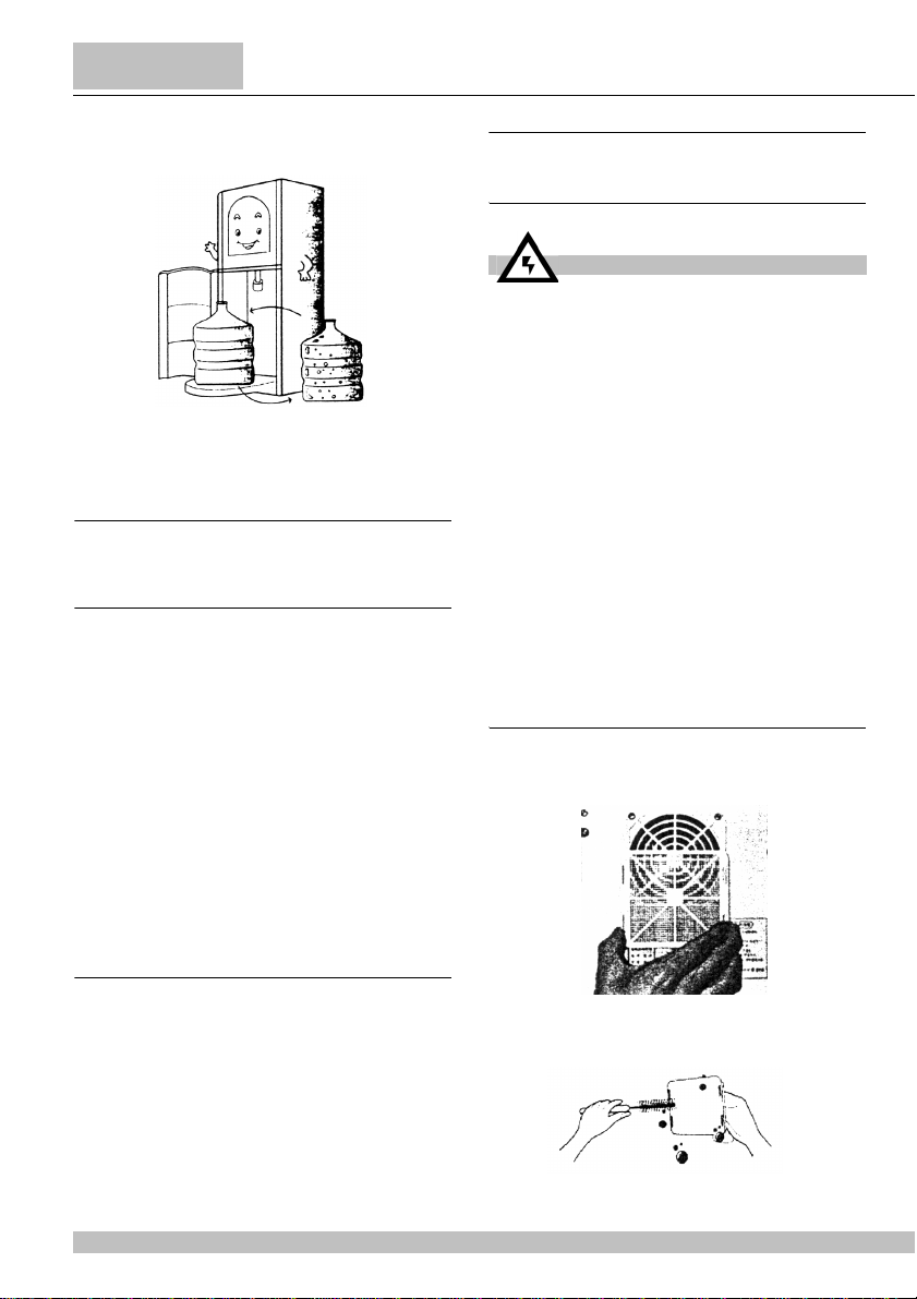
automatic features. The cabinet has a Sliding Rail
System to make it easy to load fresh water
supplies without heavy lifting. Water bottles are
installed with the open-end up to eliminate
spilling. When in operation, the water bottle’s
open end is sealed to prevent contaminationfrom
the enviroment. Ugolini cools the water with a
semiconductor Refrigeration Unit that does not
harm the enviroment. When the bottle is empty,
theempty LED will start blinking and UGOLINI will
call you with a melody. The hot water reservoir is
made of stainless steel and designed without
welded joints. The Ugolini hot & cold water
dispenser has been designed for your
convenience, taking safety, hygiene, and the
enviroment into consideration.
To take full advantage of all of the features and
benefits of this unique hot&cold water dispenser,
be sure to read this manual carefully and then
keep it in a safe place for future reference.
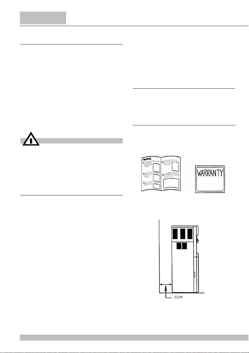
3 INSTALLATION
3. 1 TO OPERATE SAFELY
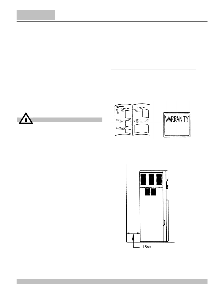
1See if the following parts are included in
the package.
2Maintain the sufficient distance (about
6-7inches, 15 cm.) between the wall and
back of BT 18/7.
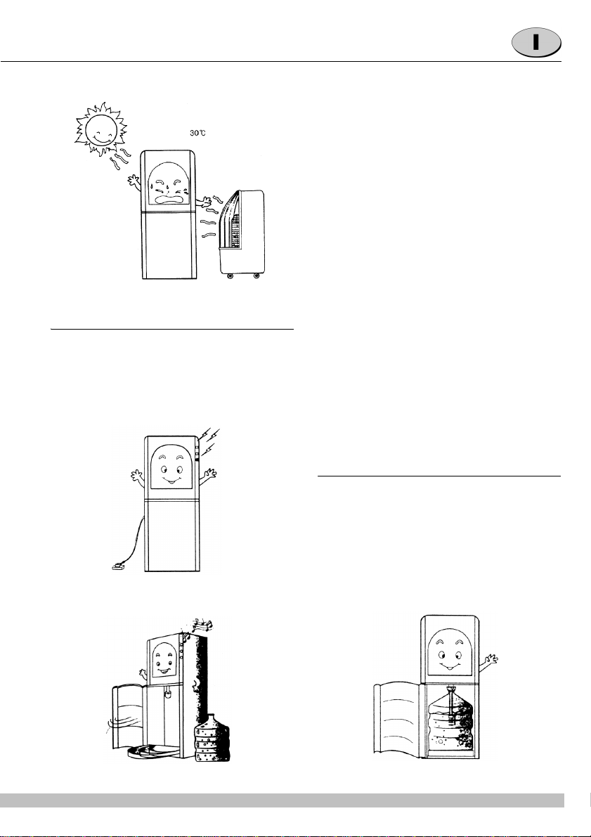
3And avoid contacting water dispenser
with direct sunlight, water and heating units.
Room temperature should not exceed 90°F
BT 18/7
Dimensions:
width cm 340
depth cm 398
height cm 1021
Net weight, approx. kg 22
Hot water tank l 2
Cold water tank l 2
Adjustable thermostats 1
Noise level lower than 70 dB (A)
IMPORTANT
Read electrical ratings written on the data
plate of the individual units; the data plate
is adhered on the dispensing side panel of
the unit, just behind the drip tray (the right
side drip tray in multiple bowl models). The
serial number of the unit (preceded by the
symbol #) is adhered just below the right
bowl. Data plate specifications will always
supersede the information in this manual.

11
(32°C) and drop below 32°F (0°C) for
optional functioning.
3. 2 OPERATING PROCEDURES
See if the cabinet door is opened and close
smoothly.
1Remove a protective adhesive tape
from the drawer. And from rear panel set
free two wire in the suction tube. Install the
“Drawer” in the “Cabinet body”.
2After inserting the power plug into a
dedicated 120 or 220 Volt power source,
turn on the power switch on the black
panel. You shoul hear2 “beeps” to signify
that the dispenser is receiving electricy.
3Open the “Cabinet Door”. If the door is
open over 5 minutes, melody alarms you to
close the door.
4Roll the “Drawer” out of the cabinet.
Remove a plastic seal from water bottle
and wipe rim, if desired, with a damp cloth.
Place a 5-gallon water bottle right on the
middle of the “Drawer” and roll back into the
“cabinet”.
5Close the “Cabinet door”.
6Then the “Suction tube” comes down
and the “pump” starts to supply water to the
hot and cold “water tank”
7Turn on the “hot water switch” placed on
the black panel.
Please turn off the hot water switch onm the
back panel when not in use.
8Allow 20 minutes for heating and three
and a half hours for cooling to the initial
setting temperature.
NOTE:
Melody will be heard the water bottle is empty
or when the door remains open for more 5
minutes. Then change a water bottle with a
new a new once or close the door correctly.
4 REPLACING THE BOTTLES
1When a water bottle is empty, the empty
LED will start blinking and BT 18/7 will call
you with a melody.

12
BT18/7
2Open the “Cabinet door”.
3Wait a few seconds until the “Suction
tube” goes up completely.
4Roll the “Drawer” out of the “cabinet”:
5Remove the empty bottle from the
“Drawer”.
6Place a new 5-gallon water bottle right
on the middle of the “Drawer” and roll it
back into the “Cabinet”.
7Close the “cabinet door”.
5 TEMPERATURE CONTROL
5. 1 HOT WATER
The Water in the hot tank is heated by a band
type heater (480W).
A temperature sensor is attached in the hot
water tank and the water temperature is
controlled by the micropocessor in the
controller preventing the heater from
overheating.
The temperature range is 194-197.6°F(90-
92°C)
5. 2 COLD WATER
The water in the cold water tank is cooled by
semiconductor refrigeration unit which is
attached in the cold water tank.
The temperature of cold water is sensed and
controlled by a temperature sensor and the
micropocessor in the controller.
The temperature range of cold water in 39.2-
41°F (4-5°C) and the temperature might be
going up if too much water is dispensed at a
time. The recovering time depends on the
enviroment conditions where the dispenser is
used.
6 CLEANING THE DISPENSER
6. 1 CLEANING THE OUTSIDE
OF THE DISPENSER
6. 2 FAN FILTER CLEANING (BI-
WEEKLY)
1Remove the cover located on the back
PART FREQUENCY MODALITY
Drawer & cabinet Weekly Towel and clea-
ning solution
Fan filter Bi-weekly Brush
Dispenser out-
side Weekly Towel and clea-
ning solution
ATTENTION
Please do not use any chemicals like ben-
zene and toluene to clean the dispenser.
These chemicals may damage the finish
and strip the color from the dispenser.

13
of the dispenser.
2Use a brush and cleaning solution to
scrub the fan clean.
3Replace the fan filter. Use the right and
left indicators on the filter to ensure proper
replacement.
6. 3 CLEANING THE INSIDE OF
THE DISPENSER (EVERY
THREE MONTHS)
6. 3. 1 CLEANING INSTRUC-
TIONS WHEN USING DI-
STILLED OR LOW TDS
(LESS THAN 4 PPM) BOT-
TLED WATER
1Turn off the power switch and remove
the power plug from the power outlet.
2Drain all the water through the cold&hot
spigots.
3Open the top cover.
4Remove the cold tank cover (yellow).
5Remove the hot tank cover (black).
Allow ample time for cooling before

14
BT18/7
removing the hot tank cover.
6Clean the tank with a washcloth dipped
with a detergent.
7Rinse each tank at least 3-4 times and
push hot&cold faucet to let the water go
out.
6. 3. 2 HOT WATER HOLDING
TANK CLEANING
METHOD WHEN USING
NORMAL MINERAL WA-
TER
1Turn off the power switch on the back of
the dispenser and remove the plug from the
power outlet.
2Open the top cover
3Remove the hot tank cover (black color)
4Add approximately 50ml. of g7
cleaning solution to the water, replace the
tank lid. (the g7 cleaning solution lid is
approximately 10 ml. 5 capfuls will provide
50 ml.)
5Drain the water and cleaning solution
through the hot water dispensing spigot
after about 15 minutes.

15
6Remove the tank cover and wipethe
inside of the tank with clean cloth.
7Plug in the power cord and turn the
power switch on and fill the hot tank with
clean water.
8Turn the power switch off and remove
the water from the tank through the hot
water spigot.
9Repeat the procedure 3 times.
6. 4 CHANGING THE AIR
FILTER
Air filter replacement frequency
6. 5 AIR FILTER REPLACEMENT
1Remove the holding tank tank cap by
unscrewing.
2Remove the air filter located near the
center of the hot or cold tank cover by
pulling up.
3Replace with a new filter.
ATTENTION
Without this periodical replacement of air
filter, contaminants removed from the air
that become trapped in the filters can leach
into the water.
AIR FILTER FREQUENCY FILTER TYPE
Hot tank air fil-
ter 12 months Stainless steel wire
mesh
Cold tank air
filter 6 months Anti-bacterial Poly
Bond

16
BT18/7
ELENCO RICAMBI
SPARE PARTS LIST
NO. PART. NO. DESCRIZIONE NAME
1 1W17X024A ASSIEME TELAIO FRAME ASS’Y
1-1 2W17V102A PANNELLO POSTERIORE INFERIORE REAR PANEL BOTTOM
1-2 1W17V051A PANNELLO LATERALE DESTRO SIDE PANEL-RIGHT
1-3 1W17V050A PANNELLO LATERALE SINISTRO SIDE PANEL-LEFT
1-4 3W17V010A PERNO INFERIORE HINGE LOW
1-5 3W17V018A TRAVERSO SUPPORTO LATERALE SIDE SUPPORT BAR
1-6 4W17G057A CUSCINETTO CUSHION
2 1W17X029A ASSIEME PANNELLO FRONTALE SUPERIORE FRONT PANEL UPPER ASS’Y
2-1 2W17T028A PANNELLO FRONTALE SUPERIORE FRONT PANNEL UPPER
2-2 3W17C011A SCHEDA LED LED PCB
2-3 4W17C161A INTERRUTTORE MAGNETICO MAGNET S/W

17
2413_07 R1.0 01C03
3 1W17X030A ASSIEME PANNELLO FRONTALE INFERIORE FRONT PANEL LOW ASS’Y
4 3W17V009A PERNO SUPERIORE HINGE UPPER
5 2W17V098A BASAMENTO BASE PANEL
6 2W17X046A ASSIEME POMPA PUMP ASS’Y
7 2W17X094A ASSIEME CORPO SERBATOIO ACQUA CALDA HOT TANK BODY TOTAL ASS’Y
8 2W19X095A ASSIEME COPERCHIO SERB. ACQUA CALDA HOT TANK COVER ASS’Y
9 3W17X149A ASSIEME FILTRO PARTE CALDA HOT FILTER ASS’Y
10 2W17X097A ASSIEME VALVOLA SOLENOIDE SOLENOID VALVE ASS’Y
10-1 3W17R140A VALVOLA SOLENOIDE SOLENOID VALVE
10-2 3W18V190B SOSTEGNO VALVOLA VALVE BRACKET
10-3 4W17G150A MANICOTTO HOSE
10-4 4W17G150B MANICOTTO HOSE
10-5 4W17G155A MANICOTTO HOSE
11 2W17X089A ASSIEME CORPO SERBATOIO ACQUA FREDDA COLD TANK BODY TOTAL ASS’Y
12 2W17X150A ASSIEME COPERCHIO SERBATOIO ACQUA
FREDDA COLD TANK COVER ASS’Y
13 3W17X150A ASSIEME FILTRO PARTE FREDDA COLD FILTER ASS’Y
14 2W17X099A ASSIEME PULEGGIA PULLEY ASS’Y
14-1 2W17T100A PULEGGIA PULLEY
14-2 2W17T096A COPERCHIO PULEGGIA PULLEY COVER
14-3 2W17V103A SOSTEGNO MOTORE MOTOR BRACKET
14-4 3W17R141A ASSIEME MOTORE MOTOR ASS’Y
14-5 3W17T151A PASSANTE MANICOTTO HOSE GUIDE
14-6 4W17T037A ACCOPPIAMENTO MANICOTTO COUPLING HOSE
14-7 3W17T034A COPERCHIO SERBATOIO ACQUA COOK WATER TANK COVER
14-8 4W17M020A INSERIMENTO INPUT
14-9 4W17T008A GUIDE PULEGGIA GUIDE PULLEY
14-10VP331A-4D MICRO INTERRUTTORE MICRO S/W
14-114W17T010A DISTANZIALE SENSORE SENSOR SPACER
15 1W17T044A CONDOTTO ARIA AIR DUCT
16 3W17T163A TUBO ARIA AIR PIPE
17 4W17T034A RUBINETTO COCK LOCK
18 RUBINETTO ACQUA CALDA HOT COCK (RED)
19 RUBINETTO ACQUA FREDDA COLD COCK (BLUE)
20 1W17X026A ASSIEME PANNELLO POSTERIORE SUP. REAR PANEL UPPER ASS’Y
20-1 2W17V085A PANNELLO POSTERIORE SUPERIORE REAR PANEL UPPER
20-2 3W17R146A ASSIEME VENTOLA FAN ASS’Y
20-3 2W17T022A COPERCHIO VENTOLA FAN COVER
20-4 2W17T025A FILTRO VENTOLA FAN FILTER
20-5 4W18T121A RIVESTIMENTO VENTILATORE FAN BUSH
21 3W17T053A CASSETTO RACCOGLIGOCCE WATER RESERVOIR BOX
22 3W17T033A GRIGLIA CASSETTO RACCOGLIGOCCE WATER RESERVOIR BOX COVER
23 1W17X025A CONTENITORE SCORREVOLE SERBATOIO
ACQUA COOK WATER GUIDE
24 1W17X027A ASSIEME PARTE CONTROLLO CONTROL PART ASS’Y
24-1 2W17V086A SOSTEGNO PARTE CONTROLLO CONTROL PART BRACKET
24-2 2W17X112A ASSIEME ALIMENTATORE SMPS ASS’Y
24-3 2W17X113A ASSIEME SCHEDA ELETTRONICA PRINCIPALE PCB ASS’Y
24-4 3W17X160A ASSIEME ALIMENTAZIONE POWER CORD ASS’Y
24-5 4W18M135A FISSAGGIO STOPPER NUT
24-6 FPG1 PORTAFUSIBILE FUSE HOLDER
24-7 FST FUSIBILE FUSE
24-8 SL112A(B) INTERRUTTORE ALIMENTAZIONE POWER S/W
24-9 SL112A(R) INTERRUTTORE RISCALDATORE HEATER S/W
25 2W17T077A COPERCHIO PARTE CONTROLLO CONTROL PART COVER
26 2W17T021A COPERCHIO SUPERIORE TOP COVER

18
BT18/7
WATER FLOW DIAGRAM
SCHEMA FUNZIONALE
CARTON BOX
IMBALLAGGIO
FRONT VIEW
VISTA FRONTALE
REAR VIEW
VISTA POSTERIORE

19
ELENCO RICAMBI
SPARE PARTS LIST
2413_07 R2.0 01C03

2413_07 R3.4 06B08
Ugolini spa
Via dei Pioppi, 33 - 20090 Opera - (MI)
Tel. 02.530059.1 - Fax. 02.530059260
www.ugolinispa.com
E-Mail: [email protected]
Table of contents
Languages:
Other Ugolini Water Dispenser manuals
Popular Water Dispenser manuals by other brands

Elkay
Elkay EFA4 1D Series Installation, care & use manual

Elkay
Elkay EZH2O LZS8WS 1A Series Installation, care & use manual

DuPure
DuPure Impression Plus Series Installation instructions & owner's manual

Elkay
Elkay EHFSA8L1Z Installation, care & use manual

Heatrae Sadia
Heatrae Sadia Aquatap Installation & user's instructions

Mistral
Mistral Horeca G80 manual

vitapur
vitapur VWD520WLP Use & care guide

Igloo
Igloo Water Cooler/Dispenser MWC496 Specification sheet

HQUA
HQUA HQUA-S350 instruction manual

GE
GE SmartWater GXSF27B Owner's Manual & Installation Instructions

Hellenbrand
Hellenbrand H200 Series Brochure & specs

Plasmatic Systems
Plasmatic Systems PLASMA-PREEN I user manual